1
21-85DF
2
[en]
[fr]
technical specifications
caractéristiques techniques
installation
installation
21 » 42
direction for use
mode d’emploi
43 » 59
product registration
enregistrement de produit
61 » 62
3
4 » 20
Stûv America thanks you for choosing a Stûv fireplace for
your home. Your fireplace was designed to provide years of
enjoyment, comfort, and safety. It was built and assembled
with the greatest care. If, for any reason, you are
dissatisfied with your fireplace, please contact your retailer.
Vous avez choisi un foyer Stûv ; Stûv vous en remercie. Il a
été conçu pour vous offrir un maximum de plaisir, de
confort et de sécurité.
Le plus grand soin a été apporté à sa fabrication.
Si malgré cela vous constatiez une anomalie, contactez
votre revendeur.
Standards & certifications
Normes & agréations
This appliance has been tested and certified by Intertek
Testing Services NA Ltd based on the following standards:
Cet appareil a été testé et certifié par Intertek Testing
services AN Ltée selon ces normes :
UL 127
ULC S-610-M93
EPA Exempt
UL 127
ULC S-610-M93
Exemption EPA
Safety instructions
Instructions de sécurité
Before installing your Stûv fireplace, please contact the local
building authorities to obtain the necessary permits and
information about applicable regulations.
Avant d’installer votre Stûv, contactez les autorités locales
pour obtenir un permis de construction ainsi que prendre
connaissance de toutes les exigences réglementaires en
vigueur.
L’installation de votre Stûv doit être confiée à un
professionnel qualifié.
Si votre Stûv n’est pas installé de façon adéquate, un
incendie pourrait s’ensuivre.
Ne pas installer le foyer dans une maison mobile.
Ne pas connecter le foyer à un système de distribution d'air
chaud.
Les instructions concernant l’installation de votre poêle à
bois sont conformes aux normes citées précédemment.
Vous devez les suivre rigoureusement afin d’éliminer tout
risque d’ennuis majeurs.
Veuillez lire attentivement ce manuel avant d’installer ou
d'utiliser votre foyer. Si votre foyer est mal installé, il peut
en résulter un incendie détruisant votre maison. Pour
réduire les risques d’incendie, suivez les instructions
d’installation. Le fait de ne pas respecter les instructions
peut occasionner des dommages à la propriété, des lésions
corporelles et même la mort.
The installation of your fireplace should be entrusted to a
skilled professional. Failure to install the fireplace correctly
can cause a fire.
Do not install the fireplace in a mobile home.
Do not connect the fireplace to an air distribution duct or
system.
The instructions for the installation of your fireplace comply
with the above standards. Please follow the instructions
closely to avoid any potential problems.
Please read this manual carefully before installing or using
your fireplace. Incorrect installation may result in fire. To
reduce the risk of fire, follow the installation instructions.
Failure to do so may result in property damage, bodily
injury, or even death.
Keep this manual handy so you can refer to it whenever
necessary.
Gardez ce manuel pour consultation ultérieure.
4
Note: We strongly recommend that our products
be installed and serviced by professionals certified
by the Association des Professionnels du Chauffage
in Quebec or by Wood Energy Technology Training
for the rest of Canada, or by the National Fireplace
Institute in the U.S.
Note : Nous recommandons fortement que nos
produits soient installés et entretenus par des
professionnels certifiés par l’Association des
Professionnels du Chauffage au Québec ou par
Wood Energy Technical Training pour le reste du
Canada, et par la National Fireplace Institute aux
États-Unis.
Technical specifications
Caractéristiques techniques
principales des appareils
Fuel type for all fireplaces:
wood logs
Type de combustible pour tous les foyers:
bûches de bois
Stûv 21/85DF
Stûv 21/85DF
Door frame dimension: 23-3/4” x 30-7/8”
Maximum power: 52 000 BTU
Efficiency : 72%
Chimney type: 10” UL-103HT
(ICC-RIS ONLY IN CANADA)
Unit weight: 550 Lbs
Wood consumed per hour: 12 - 14 Lbs / hour
Dimension du cadre : 23-3/4” x 30-7/8”
Puissance maximal : 52 000 BTU
Efficacité : 72%
Type de cheminée : 10” UL-103HT
(ICC-RIS SEULEMENT AU CANADA)
Poids de l’unité : 550 Lbs
Consommation max. bois/h : 12 - 14 Lbs / heure
5
UNIT DIMENSIONS
DIMENSIONS DE L’APPAREIL
6
EXPLODED VIEW
VUE EXPLOSÉE
7
CLEARANCE TO COMBUSTIBLE MATERIALS
DISTANCE POUR MATÉRIAUX COMBUSTIBLES
Note: The installation of two layers of 1/2" cement board under
the unit is MANDATORY. The supporting structure can be
made of wood, providing it is strong enough to support the
weight of the fireplace.
Note: L’installation de deux couches de plaque de ciment de
1/2" est OBLIGATOIRE sous l’unité. La structure qui supporte
l’unité peut être faite de bois, en autant qu’elle soit assez solide
pour supporter le poids de l’unité.
8
METAL STUDS (2X4)
OSSATURE MÉTALLIQUE (2X4)
ATTENTION: The metal framing (2X4) structure must be
insulated using stone wool insulation. Use ONLY 3" ROXUL
SAFE & SOUND or 3" AFB. Make sure the structure is
COMPLETELY filled with wool, except for the first 12" on the
lower section, which can be left open.
ATTENTION : Cette ossature métallique (2X4) doit être isolée
avec de la laine isolante. Utilisez SEULEMENT de la laine
ROXUL SAFE & SOUND 3" ou AFB 3". Assurez-vous que la
structure est COMPLÈTEMENT remplie de laine, excepté pour
les premiers 12" de la section du bas qui peut demeurer
ouverte.
9
PLACEMENT
INSERTION DE L’APPAREIL
10
FLANGES & ANCHOR PLATE
BUSELOT ET PLAQUE D’ANCRAGE
NOTE: The anchor plate is not included with the unit.
Use only a 10 inches chimney listed per UL 103HT in the US
and ICC-RIS only in Canada.
NOTE: La plaque d’ancrage n’est pas incluse avec l’appareil.
Utilisez seulement une cheminée de 10 pouces répertoriée
selon UL-103HT aux États-Unis et ICC-RIS seulement au
Canada.
11
FRONT METAL FRAME (2X3)
OSSATURE MÉTALLIQUE FRONTALE (2X3)
12
INSTALLATION
INSTALLATION
13
TOP CEMENT BOARD (1/2")
PANNEAU DE CIMENT SUPÉRIEUR (1/2")
14
TOP INSULATION
ISOLATION DE DESSUS
15
NON COMBUSTIBLE WALL SECTION
SECTION DE MUR INCOMBUSTIBLE
Note: Use 1/2" cement board to finish the hearth opening.
Other noncombustible materials can be used. The dimensions
shown below will vary when using a Stûv supplied facing or
frame. Please contact our customer service department for
details.
Note: Utilisez un panneau de ciment de 1/2" pour finir
l’ouverture de l’âtre. D’autres matériaux non combustibles
peuvent être utilisés. Les dimensions indiquées ci-dessous vont
varier avec l’utilisation d’une façade ou d’un cadre Stûv.
Communiquer avec le service à la clientèle pour plus de détails.
16
CONVECTION
CONVECTION
17
HEARTH EXTENSION
EXTENSION DE L’ÂTRE
The dimensions that are shown include the wall thickness of
3-1/4 inches of each side of the unit.
Les dimensions indiquées tiennent compte de l’épaisseur des
murs de 3-1/4 pouces de chaque côté de l’appareil.
18
CONVECTION GRILLS
GRILLES DE CONVECTION
Note: The distance between the ceiling and the center of
the hot convection grill must be at least 12". It is not
permitted to join 2 connect 2 flexible ducts as 10 feet is
the maximum horizontal length allowed. No length limit
for vertical length.
Note : La distance entre le plafond et le centre de la grille de
convection chaude doit être d’au moins 12’’. Il n’est pas permis
de raccorder 2 tuyaux ensemble, pour une distance horizontale
maximale de 10’. Il n’y a cependant pas de limite en distance
verticale.
Warm convection
out‐take
Sortie de convection
chaude
Ambiant convection
intake
Entrée de convection
ambiante
19
COMBUSTIBLE SHELF
TABLETTE EN MATÉRIAU COMBUSTIBLE
20
21
We strongly recommend reading this manual before
proceeding with the installation. Some configurations may
affect the sequence of operations.
Nous vous conseillons de lire cette notice avant de procéder
à l'installation. Certaines configurations peuvent faire varier
quelque peu l'ordre des opérations à effectuer.
Summary
Sommaire
Recommendations
When you receive your fireplace
Checking the contents
Claims
Tools needed
Unpacking
Moving
Fresh air intake
Connection to the flue
Masonry chimney
Using an existing masonry chimney
Connecting the hot-air outlets
Inserting the fireplace
Hot air circulation
Natural convection
Lining the combustion chamber
Installing baffles
Installing the applied ornamental frame (optional)
Recommandations
23
à la réception du matériel
23
Vérification du contenu du foyer
24
Réclamation
25
Outil à prévoir
25
Déballage
25
Déplacement
26
Admission d'air frais
26
Raccordement du foyer au conduit de fumée
27»29
Cheminée de maçonnerie
30»31
Utilisation d'une cheminée de maçonnerie existante
32
Placement des sorties d'air chaud
33
Placement du foyer
33»35
Circulation d'air chaud
35
Convection naturelle
36
Garnissage de la chambre de combustion
37
Placement des chicanes
38»39
Montage du cadre de finition appliqué (option)
40»41
22
Recommendations
Recommandations
We strongly recommend that you entrust the installation of
your fireplace to a skilled professional to ensure that the
characteristics of the flue are compatible with the fireplace
installed.
Nous vous recommandons instamment de confier
l'installation de votre Stûv à un professionnel qualifié qui
pourra notamment vérifier que les caractéristiques du
conduit de fumées correspondent au foyer installé.
L'installation de l'appareil doit être conforme à tous les
règlements locaux et nationaux.
Certaines parties du foyer peuvent être très chaudes lors de
son utilisation à puissance nominale.
Le rayonnement de la vitre peut être important. Veiller à ce
que les matériaux situés à proximité du foyer soient
suffisamment
distants
pour
éviter
tout
risque
d'endommagement.
Toute modification apportée à l'appareil peut créer un
danger. En outre, l'appareil ne sera plus couvert par la
garantie.
The unit must be installed in compliance with all local and
national regulations.
Some parts of the fireplace can become very hot when
operating at its rated power.
The glass door may radiate significant heat. Please make
sure that materials used in the proximity of the fireplace are
located a safe distance away to avoid any possible damage.
Modification of the unit can be dangerous.
Any modification will also invalidate the warranty.
When you receive your fireplace
À la réception du foyer
When the fireplace has been installed, please give this
manual to the user and recommend that they return the
completed Warranty certificate to Stûv America (see end of
manual).
Une fois le foyer installé, remettez cette notice à l'utilisateur
et recommandez-lui de renvoyer le certificat de garantie à
Stûv America (voir fin de notice).
Caution!
Attention !
Remove the cardboard covering the opening of the
fireplace and make sure the glass door has not been
damaged during delivery (photo 2 and 3).
Retirer le carton qui cache l'ouverture du foyer et vérifier
que la vitre ne s'est pas brisée au cours de la livraison
(photos 2 et 3).
The warranty covers transport damages providing you
contact Stûv within 48 hours of delivery.
La garantie ne couvre les détériorations dues au transport
que si elles sont signalées dans les 48 heures de la livraison.
23
Checking the contents
Vérification du contenu du foyer
In the combustion chamber you will find… (photos 1 & 2 ).
Dans la chambre de combustion, vous trouverez... (photo 1
et 2)
Touch-up spray can
Bombe de peinture pour retouches
1
Installation and User Manual
Notice d’installation et mode d’emploi
1
Fire bricks
Pierres réfractaires
8
Cold handgrip to operate door and damper
Poignée « main froide » pour manipuler la porte et le registre
2
Locking pieces for fire bricks – photo 2A
Pièces de blocage des réfractaires – photo 2A
0
Stainless steel items
Pièces inox
6
Vermiculate for lower baffle kit
Vermiculites pour kit chicanes inférieures
4
We suggest removing all elements that are inside the
combustion chamber so as to make the fireplace lighter to
move around.
Nous vous conseillons de retirer tous les éléments qui se
trouvent dans la chambre de combustion pour alléger le
foyer et le déplacer plus facilement (photo 3).
24
Claims
Réclamation
For warranty coverage, please provide the manufacturer’s
serial number, which is visible on the upper-right section of
the opening (photo 4).
En cas de réclamation, communiquez toujours le n° de série
du foyer visible sur la partie supérieure droite de la
devanture, dans le retour (photo 4).
Tools (Pic. 5)
Outils à prévoir (photo 5)
- crowbar
- level
- hammer
- screw gun (10 mm socket and Philips bits)
- standard screwdriver
- Phillips screwdriver
- 3 and 5 mm Allen keys
- pliers
– un pied de biche
– un niveau
– un marteau
– une visseuse (douille de 10 mm et embouts cruciformes)
– un tournevis plat
– un tournevis cruciforme
– une clé Allen de 3 mm et de 5 mm
– une pince
Unpacking
Déballage
Note :
Remarque :
- For transport, the window is secured in its intermediate
position.
- The paint is not oven-baked and is therefore relatively
fragile, but it will harden when heated. Care should be
taken when handling the unit during installation.
- Remove protective strip from window (photograph 6).
- Remove vertical front slats with crowbar (photo 7).
- Remove top section of packing (photo 8).
– Pour le transport, la vitre est immobilisée en position
intermédiaire.
– La peinture n'est pas cuite au four ; elle est donc
relativement fragile mais elle durcira lors des premières
chauffes ; par conséquent, manipuler l'appareil avec
précaution lors de son installation.
– Retirer la bande de protection de la vitre (photo 6).
– À l’aide du pied de biche, retirer les lattes verticales avant
(photo 7).
– Retirer la coiffe supérieure de l’emballage (photo 8).
25
Moving
Déplacement
There are three different ways of moving the fireplace:
- using a forklift: leave it on the pallet
- with a two-wheel hand trolley: tilt the fireplace backwards
and leave the pallet in place
- with the reversible handles designed for this purpose: (e.g.
when placing the unit on a base).
Vous pouvez déplacer le foyer de 3 manières différentes :
– avec un transpalette : le laisser sur sa palette.
– avec un diable : basculer le foyer sur son dos, laisser la
palette sur place.
– avec les poignées conçues à cet effet : elles sont
réversibles (p.ex. placement sur un socle).
Caution!
Once the fireplace has been moved near its final location,
unlock the counterweights using the 3mm Allen key
(photograph 1). Remember to perform this operation
before inserting the fireplace into the enclosure. Make sure
the window moves properly, then raise it to its full height
(photograph 2). Check that the counterweight cables run in
the grooves of the pulleys (photograph 13).
Attention !
Une fois le foyer à proximité de son emplacement final,
débloquer les contrepoids à l’aide de la clé Allen 3mm
(photo 1). Ne pas oublier d'effectuer cette opération avant
d’encastrer le foyer dans la niche.
Vérifier que la vitre coulisse correctement ; la remonter
ensuite au maximum (photo 2).
Vérifier que les câbles des contres-poids sont logés dans les
gorges des poulies (photo 3).
Ne jamais basculer la porte de plus de 90°.
Never tilt the door more than 90°.
Fresh air inlet
Admission d’air frais
When operating with an open fire, the Stûv 21 consumes a
large amount of air. Therefore, we recommend providing an
external air supply (fig. 3), although this is not mandatory.
En fonctionnement à feu ouvert, le Stûv 21 consomme
beaucoup d’air. Il est donc préférable, mais non obligatoire,
de prévoir une arrivée d’air qui proviendra de l’extérieur
(fig. 3).
L’alimentation d’air, qui varie selon le modèle, débouchera
idéalement sous le foyer, vers l’avant du foyer, et sera
équipée d’un registre de fermeture (figure 4 A
#12001002).
The air intake, which varies depending on the model,
should ideally be located beneath the front of the unit and
incorporate a shut-off register (fig. 4 A #12001002).
DO NOT CONNECT THIS AIR INLET TO THE STOVE.
model
Stûv 21/85 DF
NE PAS RACCORDER CETTE ALIMENTATION AU FOYER.
minimum diameter
modèle
21/85 DF
6" Ø
Note: Any extractor (kitchen hood, air-conditioning)
operating in the same room or in an adjacent room can
adversely affect your Stûv's operation (back-draughts).
section minimale
6" Ø
Remarque : Tout extracteur (hotte, air-conditionné…) situé
dans le même espace ou dans une pièce contigüe peut
perturber le bon fonctionnement de votre Stûv (risque de
refoulement).
Cette étape est cruciale pour les maisons à haut rendement
énergétique.
This step is crucial for homes that are highly energy
efficient.
26
Connection to the chimney
Raccordement au conduit de fumée
Caution :
Attention :
Care must be taken during installation. Shortcuts or
compromises may result in safety hazards or even fire.
N’employez pas de moyens de fortune pendant
l’installation: ils pourraient devenir dangereux et entraîner
un incendie.
Ne reliez pas cet appareil à une cheminée qui dessert un
autre appareil de chauffage. Ne coupez ni chevrons ni
solives de plafond sans consulter au préalable un agent du
service du bâtiment pour éviter de compromettre
l’intégralité structurale.
Do not connect the unit to a chimney used for another
appliance.
Do not cut rafters or ceiling joints without first consulting a
building official to ensure that structural integrity is not
compromised.
Use only a chimney that complies with UL-103HT or ULCS629 (2100°), depending on the applicable standards in
your area.
Utiliser uniquement une cheminée répertoriée selon la
norme UL-103HT aux Etats-Unis et ICC-RIS au Canada
selon les normes d’installations en vigueur dans votre
localité.
A chimney serving as an outlet for a fireplace cannot be
used for any other appliance.
Une cheminée servant d'évacuation à un foyer ne doit servir
pour aucun autre appareil.
Caution: The illustrations on page 17 show different
chimney configurations. Please refer to the chimney
manufacturer's instruction manual for appropriate and safe
installation details.
Attention : les schémas en page 30 illustrent les diverses
configurations possibles d’installations de cheminées. Vous
devez toutefois vous référer au manuel d’instructions du
manufacturier de cheminée pour les détails d’installation
appropriés.
Before connecting the chimney, make sure the fireplace is in
its final position and that it is level.
Avant d’effectuer le raccordement, vérifier que le foyer se
trouve à sa place définitive et qu’il est de niveau.
Standard inside diameter of outlet:
Stûv 21/85DF 10"
Diamètre standard de la sortie :
Stûv 21/85DF 10"
Allowable chimney heights from below the unit to the rain
cap:
Hauteurs de cheminée permises de sous l’appareil au
chapeau de pluie :
Minimum 15'
Maximum 45'
minimum 15’
maximum 45’
It is recommended, but not mandatory, that a straight
chimney section be installed between the unit and an offset.
Il est préférable mais pas obligatoire d’installer une première
section de cheminée droite entre l’appareil et une déviation.
27
If several existing flues are available (fig.1a and 1b):
- use only one of them (fig. 1b)
- seal the unused flues at the top and bottom and, in
general, make sure that the enclosure in which the fireplace
is located is sealed to prevent outside cold air from cooling
the house (Fig. 1b).
Any unused flue (fig. 1a) or vented cavity in the walls is
liable to generate unwanted back-draughts.
Si plusieurs conduits sont disponibles (fig. 1a & 1b) :
– n’en utiliser qu’un seul (fig. 1b).
– boucher en haut et en bas les conduits non utilisés et
d’une manière générale, veiller à ce que le plafond de la
niche dans laquelle est enfermé le foyer soit bien étanche
pour éviter que de l’air froid en provenance de l’extérieur
ne vienne refroidir l’intérieur de la maison (fig. 1b). Un
conduit non utilisé (fig. 1a) ou un vide-ventilé entre murs
peuvent provoquer un contre-tirage très préjudiciable.
This should be avoided.
À proscrire !
28
29
Masonry chimney
Cheminée de maçonnerie
Installing your Stûv fireplace with a masonry chimney
requires use of the ICC-RIS chimney from the top of the
fireplace to the wall where it will connect to an approved
rigid duct that will run inside the masonry chimney (see
figure on next page).
L’installation de votre foyer Stûv avec une cheminée de
maçonnerie nécessite quand même l’installation d’une
section de cheminée ICC-RIS au-dessus du foyer jusqu’à la
connexion avec la gaine rigide homologuée qui doublera
l’intérieur de la cheminée de maçonnerie (voir figure page
ci-contre).
Une gaine rigide d’acier inoxydable doit être installée à
l’intérieur de la gaine d'argile cuite à l’intérieur de la
cheminée de maçonnerie. La gaine rigide ne remplace
d’aucune façon la gaine d’argile cuite. Vous pouvez utiliser
toute gaine homologuée selon les normes ULC-S635, ULCS640 ou UL-1777.
Vous devez vous assurez d’avoir une bonne connexion
solide entre la section de cheminée ICC-RIS et la gaine
rigide. Un adaptateur de maçonnerie (FO-FDM7) a été
conçu spécifiquement pour cet usage et est disponible chez
un détaillant ICC. Cet adaptateur s’attache avec 3 rivets
(fournis) à la gaine rigide et avec 3 vis (fournies) à la
cheminée ICC-RIS. Une fois le mortier en place, le joint
entre la cheminée EXCEL et la gaine rigide ne devrait pas
être visible afin d’isoler la chaleur dégagée à travers la gaine
de l’enclos du foyer. Tel qu’il est montré sur la figure de la
page ci-contre, vous devez installer au minimum une
longueur de 46 cm de cheminée ICC-RIS après le coude de
cheminée ICC-RIS.
Le point le plus élevé de la cheminée ICC-RIS – là où la
cheminée entre dans la cheminée de maçonnerie – ne doit
pas être à moins de 31 cm des matériaux combustibles du
plafond.
The rigid stainless steel liner should be inserted inside the
clay liner within the masonry chimney. It is not meant to
replace the clay liner. You can use any approved liner that
complies with ULC-S635, ULC-S640, or UL-1777.
Special care should be taken to make sure that you have a
solid connection between the ICC-RIS chimney section and
the liner. A masonry adaptor (FO-FDM7) has been
designed specifically for this purpose and is available from
your ICC dealer. It attaches to the liner with 3 stainless steel
rivets (provided) and to the ICC-RIS chimney with 3 screws
(provided).
After cementing, the connection between the ICC-RIS
chimney and the liner should not be visible in order to
insulate the heat released through the liner from the
fireplace enclosure. As shown in the illustration on the next
page, you must install at least one 18'' length of ICC-RIS
chimney after the ICC-RIS chimney elbow. The uppermost
part of the ICC-RIS chimney - where it enters the masonry
chimney - must be a minimum of 12'' from any combustible
materials in the ceiling.
Notes:
Remarque :
If the ceiling is high enough, you can install one or more
ICC-RIS chimney lengths directly on the fireplace before the
elbow.
If you use a flexible liner, care must be exercised when
cleaning to ensure that the flexible stainless steel liner is not
dislodged in any way.
Si la hauteur du plafond le permet, vous pouvez installer
une des longueurs de cheminée ICC-RIS directement sur le
foyer, avant le coude.
Si vous utilisez une gaine flexible, le nettoyage devra être
effectué délicatement afin de ne pas risquer de déplacer
celle-ci.
30
31
Using an existing masonry chimney
Utilisation d’une cheminée de maçonnerie
existante
Warning. If you are considering using an existing chimney,
it must first be thoroughly inspected by an organization
qualified to determine the following:
Mise en garde : si vous envisagez d'utiliser une cheminée de
maçonnerie existante, vous devez la faire inspecter au
préalable par les autorités compétentes afin de confirmer les
points suivants :
- The masonry chimney is well constructed and fully lined,
in accordance with local building codes and the National
Building Code of Canada (NBC) or the National Fire
Protection Association chimney standard (NFPA 211).
- It has been thoroughly cleaned of any soot or creosote
residue and inspected to determine that it is in good
working condition.
- There is no insulation of any type in contact with the
masonry chimney and there is no insulation stuck anywhere
in the chimney.
- All the necessary clearances around the masonry chimney
and along its complete length comply with NBC or NFPA
211 codes. If the masonry chimney is enclosed in drywall,
openings will probably be required in order to check the
clearances.
- The masonry chimney will only be used as a fireplace and
with no other appliance.
La cheminée de maçonnerie est construite suivant les règles
de l'art, est entièrement doublée et respecte les règlements
municipaux ainsi que le Code national du bâtiment du
Canada (CNB) ou la norme de l’association nationale de
protection contre les incendies (NFPA 211). La cheminée de
maçonnerie a été entièrement nettoyée de tout résidu de
suie et de créosote et a été inspectée pour confirmer qu’elle
est toujours en bon état de fonctionnement. Il n’y a aucun
isolant, quelle qu’en soit la sorte, en contact avec la
cheminée de maçonnerie et il n’y a aucun isolant, quelle
qu’en soit la sorte, qui se trouve coincé quelque part dans la
cheminée.
Tous les dégagements nécessaires autour de la cheminée de
maçonnerie, sur toute la longueur de celle-ci, sont respectés
selon CNB ou NFPA 211. Si la cheminée de maçonnerie est
encloisonnée derrière des panneaux de Placoplatre, des
ouvertures devront être pratiquées afin de confirmer tous
les dégagements.
La cheminée de maçonnerie sera utilisée uniquement pour
le foyer et pour aucun autre appareil.
Si des réparations majeures sont nécessaires pour rencontrer
les points mentionnés ci-dessus, une nouvelle cheminée de
maçonnerie devra être construite.
Pour faire le trou dans la cheminée de maçonnerie et faire le
raccordement avec le foyer, nous vous recommandons de
suivre les étapes suivantes : Déterminez et indiquez
l’endroit d’insertion de la cheminée ICC-RIS dans la
cheminée de maçonnerie.
En utilisant une grosse mèche de maçonnerie (3/4 – 2’’),
percez un trou exactement au centre du tracé ovale. À
l’aide d’un marteau de maçonnerie et d’une perceuse,
élargissez graduellement le trou jusqu’à la grandeur désirée.
N’oubliez pas de travailler du centre du trou vers l’extérieur.
Soyez particulièrement prudent en perçant la gaine en argile
cuite derrière la brique car les trois autres côtés doivent
rester en place.
Glisser la gaine d’acier inoxydable du haut de la cheminée
vers le bas.
Si vous utilisez une gaine rigide, vous aurez besoin d’assez
d’espace pour fixer un coude avec au moins 2 rivets. Si la
gaine rigide glisse difficilement ou si la cheminée de
maçonnerie offre une ouverture intérieure inférieure à 10’’
X 10’’, une gaine flexible homologuée peut être utilisée
avec un adaptateur flexible/rigide (LM-7LAF) disponible
chez votre détaillant.
Installez le coude de gaine rigide et l’adaptateur de
maçonnerie à l’extrémité inférieure de la gaine.
Avancez le foyer afin d’y installer la cheminée ICC-RIS
(coude et longueur) puis reculez le foyer en place tout en
reliant la cheminée ICC-RIS à l’adaptateur de cheminée de
maçonnerie.
If major repairs are required to comply with the above
requirements, a new chimney should be constructed.
To make the hole through the masonry chimney and make
the connection to the fireplace, we recommend that you
follow these steps:
Locate and mark the spot where the ICC-RIS chimney will
be inserted into the masonry chimney.
Using a large (3/4 - 2'') masonry bit, drill a hole exactly in
the center of the oval outline. With an impact hammer and
drill, slowly enlarge the hole to the size required. Remember
to work from the center out. Be especially careful with the
clay liner behind the brick because three sides of it must
stay in place.
Slide the stainless-steel liner down from the top of the
chimney. If you are using rigid liner you will need enough
room to secure an elbow to it with at least two screws.
If it is difficult to install the rigid stainless-steel liner in the
existing masonry chimney or if the inside diameter of the
masonry chimney is less than 10'' X 10'', an approved
flexible stainless-steel liner can be used along with a
flexible/rigid adapter (LM-7LAF) available from your dealer.
Install the liner elbow and masonry adapter on the lower
edge of the liner.
Move the fireplace forward to install the ICC-RIS chimney
on it (elbow and section), then move the fireplace back as
you connect the masonry adapter to the ICC-RIS chimney.
32
Connecting the hot-air outlets
(mandatory)
Raccordement des sorties d'air chaud
(obligatoire)
A minimum of 2 room air inlets and 2 hot-air outlets are
required.
Un minimum de 2 entrées d’air ambiant et 2 sorties d’air
chaud est requis.
Use only the Stûv convection system kit.
Remove the knockout parts by tapping as closely as possible
to the side nearest the smoke outlet. Then screw in the
flanges. Attach the hot-air outlets using clamping collars.
Utilisez uniquement le système de convection fournit par
Stûv.
Retirer les prédécoupes en tapant le côté le plus près
possible de la sortie de fumée, retirer la laine isolante et
retirer les deuxièmes prédécoupes au fond du trou. Vissez
ensuite les collerettes.
Fixer les conduits d’air chaud a l’aide de colliers de serrage.
Placing the fireplace in position
Placement du foyer
Note:
Remarque :
- The fireplace must rest on an adequate bearing surface.
- It must be installed to facilitate access for cleaning the
hearth, the connecting duct, and the smoke outlet.
- It must be free to expand when hot. In no case must the
masonry, walls, or ornamental trim be allowed to contact
the hearth. Allow at least a 3/16_ gap.
- For the door to open correctly, the surface finish of the
wall must be on the same level as the base of the hearth
opening (photo 1).
– Le foyer doit être installé sur un sol ayant une portance
suffisante.
– Il doit être installé de façon à faciliter l’accès pour le
nettoyage du foyer, du conduit de raccordement et du
conduit de fumée.
– Le foyer doit pouvoir se dilater librement. En aucun cas, la
maçonnerie, les murs ou les matériaux décoratifs ne devront
entrer en contact avec celui-ci ; prévoir au moins 5 mm de
jeu.
– Pour un basculement correct de la porte, la finition du
mur doit se trouver au même niveau que la base de
l'ouverture du foyer (photo 1).
33
The fireplace will stand:
Le foyer sera posé soit :
– on 2 layers of 1/2" cement board or;
– on a masonry base or;
– on an adjustable Stûv base (optional).
– sur deux épaisseurs de fibro-ciment 1/2".
– sur un socle maçonné,
– sur un podium ajustable Stûv (fourni en option).
1. On cement boards or a masonry base:
1. sur les panneaux de fibro-ciment ou sur un socle
maçonné :
Level the fireplace with the four adjustable struts, accessed
from inside the combustion chamber. Use a 5- mm Allen
key to adjust the height at the four corners (photo 1).
Placer le foyer de niveau grâce aux 4 pieds à rotule
réglables en hauteur depuis l’intérieur de la chambre de
combustion. Utiliser la clé Allen de 5mm pour le réglage de
la hauteur des 4 coins (photo 1).
2. On the optional Stûv base:
Remove the two M10x40 screws (four in total) attached to
each leg (photo 2). Tilt the fireplace to lay it on its back,
then remove the adjustable struts located under the
fireplace (photo 3). Screw them onto the base for the full
length of the thread without tightening them (photo 4).
2. sur un podium Stûv (option) :
Retirer les 2 vis M10 X 40 fixées sur chaque pied (4 au
total) (photo 2). Coucher le foyer sur son dos, retirer les
pieds à rotule réglables (photo 3). Revisser complètement
les pieds à rotule (sans les bloquer) sur le podium (photo 4).
Caution: To prevent any unwanted air flow inside the
hearth, seal the threads that held the adjustable struts with
the extra M10x40 screws (photo 5). Remove the four caps
by prying them off (photo 6). If necessary, recut the base
elements so that the fireplace can be raised to the required
height. Insert these into the square holes (photo 7).
Attention : Pour éviter une circulation d’air parasite dans le
foyer, revisser les vis M10 X 40 dans les trous où étaient les
pieds à rotule réglables (photo 5).
Retirer les 4 opercules en faisant levier (photo 6). Recouper
éventuellement les éléments de piétement de sorte que le
foyer soit surélevé de la hauteur voulue ; les introduire dans
les trous carrés dégagés (photo 7).
Les piètements ne sont pas symétriques, placer les grands
côtés vers l’avant du foyer.
Sans recoupe, ils rehaussent le foyer de 44,3 cm ;
l’ouverture du foyer se trouve alors à 60 cm du sol (photo
9).
Because they are not symmetrical, the longer sides of the
base elements should be placed toward the front of the
fireplace. If these are not cut, they will raise the fireplace
17-1/2" with the hearth opening at 23-3/4" above floor
level (photo 9).
34
25
To calculate the re-cut:
Calcul de la recoupe :
Opening of fireplace before recut minus required fireplace
opening height.
Ouverture du foyer sans recoupe moins ouverture du foyer
désirée.
If you wish to have the fireplace opening at a height of 173/4": 23 3/4" - 17 3/4" = 6" recut.
Si vous désirez avoir votre ouverture foyère à une hauteur
de 45 cm :
60 cm - 45 cm = 15 cm de recoupe.
Redresser le foyer (photo 8). Le placer à son emplacement
définitif et régler le niveau à l’aide de la clé Allen de 5mm
(photo 9).
First, place the fireplace (photo 8) in its initial position. Then
place the fireplace in the desired location and level the unit
using the 5mm Allen key (photo 9).
Convection air circulation
Circulation de l’air de convection
Convection air can route one or more hot air outlets to a
room other than the one in which the Stûv 21 is installed
(verify with your local authorities). In this case, warm air
delivery must be compensated by a return duct to avoid air
depression in the room and its associated hazards of
impeded draught (Fig. 11).
A grilled opening in the wall should have a section at least
equal to that of the hot air outlet from the fireplace.
On peut diriger une ou plusieurs sorties d’air chaud vers un
local autre que celui où est installé le Stûv 21 (Vérifier avec
les autorités locales). Dans ce cas, il faut compenser ce
départ d’air par une gaine de retour pour éviter que la pièce
où se trouve le foyer ne soit en dépression, avec les risques
de refoulement que cela comporte (figure 11).
Prévoir dans le mur une grille dont la section est au moins
égale à celle de la sortie d'air chaud du foyer.
35
Natural convection (Fig. 1)
Convection naturelle (fig. 1)
Caution, this step is crucial for the proper performance of
your fireplace!
Attention, cette étape
fonctionnement du foyer !
To get the most efficiency from your Stûv 21, we
recommend that as many air inlets/outlets as possible be
installed. Using a hammer, open at least 2 of the 6 fresh-air
inlet knockouts in the bottom part of the stove (1 left and
1 right) and at least 2 of the 8 hot-air outlets in the upper
part (photo 42).
Operate symmetrically to avoid any overheated areas. This
will allow convection between the outer skin of the
fireplace and the combustion chamber (fig 1).
Afin de profiter au mieux de votre Stûv 21, nous vous
recommandons d'utiliser un maximum d’entrées et de
sorties d’air. À l’aide d’un marteau, libérer au moins 2 des 6
entrées d’air pré-découpées (1 à gauche et 1 à droite) dans
la partie inférieure du foyer et au moins 2 des 8 sorties d’air
chaud (1 à gauche et 1 à droite) dans la partie supérieure
du foyer (photo 2). Effectuer cette opération de manière
symétrique pour éviter des zones de surchauffe. Ceci
permettra une convection entre l’enveloppe extérieure du
foyer et la chambre de combustion (fig 1).
Flange installation
Placement des buselots
Use the 10 mm socket driver to attach the flanges (photo
3). They provide an attachment base for a 6" Ø flexible duct
connection. These ducts will direct warm air directly from
the hearth to an adjacent room without carrying any dust
that could be suspended between the walls and the hearth.
À l’aide d’une visseuse avec une douille de 10, placer les
buselots fournis (photo 3). Ces buselots permettent le
raccordement des conduits flexibles de diamètre 150 mm.
Ce gainage conduit l’air chaud directement du foyer vers la
pièce à chauffer sans entraîner les poussières en suspension
entre la maçonnerie et le foyer.
36
est
cruciale
pour
le
bon
6
Lining the combustion chamber
Garnissage de la chambre de combustion
Place the primary air diffuser in position or check its position
(the diffuser's lugs fit into slots designed to receive them)
before positioning the refractors (photos and Fig. 1 to 5).
Placer le diffuseur d’air primaire ou vérifier sa position (les
ergots du diffuseur se logent dans les encoches prévues à
cet effet) avant de placer les réfractaires (photos & fig. 1 à
5).
Positioning the refractor panels:
Placement des réfractaires :
Positioning the refractor panels:
- Make sure you always position chamfers towards the
inside of the hearth.
- Follow the sequence indicated in Fig. 6.
- For final adjustment of the alignment of the refractors, use
a flat screwdriver.
– veiller à placer toujours le chanfrein vers l’intérieur du
foyer ;
– suivre l’ordre indiqué (fig. 6) ;
– pour ajuster l’alignement des réfractaires, faire levier avec
un tournevis plat.
Model 21/85 (Fig. 6) :
modèle 21/85 (fig. 6) :
– garnissage du fond : placer les réfractaires, battée vers
l’avant ;
– placer les réfractaires latéraux au maximum vers l’avant
(battée vers l’avant du foyer) de manière à pouvoir
introduire les réfractaires garnissant le dos.
- Lining the bottom: insert the refractors, with the rabbet
toward the front.
- Place the side refractors as far forward as possible (with
the rabbet towards the front of the fireplace) so you can
insert the refractors lining the back wall.
37
Upper baffle installation
Placement de la chicane supérieure
Photo 8: lower baffle kit.
Photo 8 : kit chicane inférieure.
Note that R/H and L/H supports are different (photo 10).
The short 1.57" lug should be turned toward the inside of
the hearth (photo 9 and 10). These side supports should
rest at the bottom of the hearth on the edge of the
rearmost refractor bricks and in the metal groove in front
(photo 11).
These supports must run perfectly parallel to the side
refractor plates (Fig. 12). Check to make sure that the tip of
the support is well lodged in the groove and that it is not
stuck between the tip of the groove and the hearth wall
(photo 13).
Attention, le support droit et gauche sont différents (photo
10) ; la petite patte de 4 cm doit être tournée vers l'intérieur
du foyer (photos 9 & 10). Ces supports latéraux doivent
prendre appui dans le fond du foyer sur la tranche du
réfractaire du fond et à l’avant, dans la gouttière métallique
(photo 11).
Attention, les supports doivent être bien parallèles aux
réfractaires latéraux (fig. 12).
Vérifier que la pointe du support est bien logée dans la
gouttière et qu‘elle n’est pas coincée entre l'extrémité de la
gouttière et la paroi du foyer (photo 13).
38
Position the front crosspiece (photo 1). Its lug should rest in
the notch of the side support (photo 2 and 3).
Placer la traverse avant (photo 1). L’ergot de la traverse doit
venir se loger dans l’encoche du support latéral (photos 2 et
3).
Note: Supports for the North American market have only
one notch.
Note: Les supports destinés au marché nord-américain n'ont
qu'une seule encoche.
Insert the vermiculite plates according to model (photo 4).
Secure and center the entire assembly: stainless steel
supports and vermiculite plates (photo 5).
Placer les plaques de vermiculite – suivant modèle – (photo
4). Resserrer et centrer l’ensemble des pièces : supports
inox et plaques de vermiculite (photo 5).
39
Fitting the applied ornamental
frame (option)
Montage du cadre de finition
appliqué (option)
As its name implies, this type of frame is applied in front of
the masonry. It is secured with a counter-frame joining the
hearth (behind the wall) and the frame (in front of the
wall). An appropriately sized recess must first be made (see
page 8).
Comme son nom l’indique ce type de cadre s’applique
devant la maçonnerie ; il se monte par l’intermédiaire d’un
contre-cadre qui assure la jonction entre le foyer (derrière la
maçonnerie) et le cadre (devant la maçonnerie). Vous aurez
prévu une niche aux dimensions adéquates (voir page 8).
Counter-frames are available from Stûv to fit various wall
thicknesses from 3" to 5".
Stûv propose 2 modèles de contre-cadres réglables suivant
l’épaisseur du matériau d’encastrement du foyer : de 50 à
75 mm et de 75 à 125 mm.
À l’aide d’un petit tournevis plat, ouvrir les 4 languettes
situées sur les montants avant du foyer (photo 6). Mesurer
la profondeur entre le plan avant de la maçonnerie et le
bord avant du foyer. Reporter la mesure pour établir la
profondeur du contre-cadre (photo 7).
À l'aide d’une clé Allen de 3mm et la douille de 8mm,
bloquer la profondeur du contre-cadre (photo 8). Effectuer
ces opérations pour les 4 coins.
Using a small flat screwdriver, open the 4 brackets on the
front uprights (photo 6). Measure the distance between the
finish wall and the front edge of the fireplace. This
measurement defines the depth of the counter-frame
(photo 7). Using a 3mm Allen key and an 8mm socket,
tighten the counter-frame at all 4 corners at the required
depth (photo 8).
40
Secure counter-frame (photo 1).
Make sure not to insert it upside-down (Fig. 2). Adjust the
height of the counter-frame by bending the brackets as
required on the fireplace uprights. Fit the ornamental frame
in place (photo 3 and 4). Nuts and bolts are attached to the
frame and are positioned inside the holes (keyhole-shaped)
of the counter-frame.
Accrocher le contre-cadre (photo 1).
Attention au sens (fig. 2). Ajuster la hauteur du contrecadre en pliant plus ou moins fort les languettes des
montants du foyer.
Placer le cadre de finition (photos 3 & 4). Des goujons et
écrous sont fixés sur le cadre et vont se placer dans les
boutonnières (trous de serrure) du contre cadre.
Once the fireplace has been installed, it should be tested.
Please refer to the "Directions for Use" section of this
manual.
Lorsque l'installation du foyer est terminée, effectuer un test
de fonctionnement du foyer. Se référer à la partie mode
d'emploi de ce document.
41
42
43
Stûv America thanks you for choosing a Stûv fireplace for
your home. Your fireplace was designed to provide years of
enjoyment, comfort, and safety. It was built and assembled
with the greatest care. If, for any reason, you are
dissatisfied with your fireplace, please contact your retailer.
Vous avez choisi un foyer Stûv ; Stûv vous en remercie. Il a
été conçu pour vous offrir un maximum de plaisir, de
confort et de sécurité.
Le plus grand soin a été apporté à sa fabrication.
Si malgré cela vous constatiez une anomalie, contactez
votre distributeur.
Recommendations
Recommandations
– We recommend you entrust the installation of your
fireplace to a skilled professional.
– Please read the user manual carefully and follow the
maintenance instructions.
– Please fill in the warranty form and return it to Stûv
America Inc. Be sure to include your appliance’s serial
number (which you’ll find in the upper right corner on the
face of your fireplace) (see photo 1).
– Please make sure your fireplace is regularly maintained
(see pages 50 to 59).
– Confier l'installation du foyer à un professionnel qualifié,
– Lire attentivement ce mode d’emploi et respecter les
consignes d’entretien,
– Nous retourner le certificat de garantie dûment complété
en mentionnant bien le n° de série de l'appareil, visible sur la
partie supérieure droite de la devanture, dans le retour
(photo 1),
– Assurer un entretien régulier du foyer (voir pages 51 à
60).
Precautions
Attention
– Do not use chemicals or fluids to ignite the fire.
– Do not use the fireplace when the door is open unless you
have installed a fire screen (optional).
– Always close the door after ignition.
– Do not burn waste materials or flammable liquids, such as
gasoline, naphtha or motor oil.
– Your Stûv can become extremely hot. Do not allow
children or domestic animals to touch the fireplace when in
use.
– Combustible materials, such as firewood, wet clothes, and
so on, placed too close to the appliance are liable to catch
fire.
Objects placed in front of the fireplace should be kept at a
distance of at least 1.22 m (48”) from the glass front.
– Do not let the fireplace get so hot that some parts begin
to glow red.
– Burn firewood directly on the refractor plates. Do not use
a firedog and do not attempt to lift the fire.
– Any modification may be dangerous and will invalidate
your warranty. Use only original Stûv spare parts for repair
or replacement.
– Air inlets and outlets should always remain free.
– Ne pas utiliser de produits chimiques ou autres liquides
pour allumer le feu.
– Ne jamais utiliser le foyer la porte ouverte sauf si munie
d’un pare-étincelle (option)
– Toujours fermer la porte après la période d'allumage.
– Ne pas brûler de déchets et/ou de liquides inflammables
comme l'essence, le naphte et l'huile de moteur.
– Votre Stûv peut devenir très chaud : il faut empêcher les
enfants et les animaux domestiques de toucher le foyer
lorsqu’il fonctionne.
– Les matériaux combustibles tels que le bois de chauffage,
les vêtements mouillés, etc. placés trop près de l’appareil
pourraient prendre feu. Les objets placés devant l’appareil
doivent être gardés à une distance d’au moins 1,22m (48")
de la face vitrée de l’appareil.
– Ne laissez pas le foyer chauffer au point où des parties
deviennent rougeoyantes.
– Brûlez le bois de chauffage directement sur les briques
réfractaires. N’utilisez pas de chenet et n’essayez pas de
surélever le feu de quelque façon.
– Toute modification apportée à l'appareil peut créer un
danger et vous privera de bénéficier de la garantie ; en cas
de réparation, n'utiliser que des pièces de rechange Stûv.
– Les entrées et sorties d'air doivent toujours rester libres.
44
– En cas de feu de cheminée :
- à l'aide de la main froide, fermer le registre d'air au
maximum (à fond vers la gauche),
- appeler les pompiers,
- éteindre le feu avec un extincteur à poudre, de la soude
(sel) ou du sable (surtout pas d'eau),
- ventiler la pièce dans lequel se trouve le foyer,
- Suite à un feu de cheminée, faire nettoyer et inspecter la
cheminée par un professionnel. La faire réparer si
nécessaire.
– If there is a fire in the chimney:
- use the “cold” handgrip to close the air inlet (full left)
- call the fire department
- put out the fire with a powder extinguisher, salt, or sand
(never use water)
- ventilate the room
- after a fire in the chimney, have the flue cleaned and
inspected by a professional and repaired if necessary.
Fuel
Les combustibles
Which wood should you choose?
Quel bois choisir ?
Different types of wood have different heat capacities and
do not burn in the same way. Generally speaking you
should use hard wood such as oak, beech, ash, hornbeam,
or fruit trees. These produce beautiful flames and abundant
embers, which will glow for a long time.
Les différentes essences de bois ont des pouvoirs
calorifiques différents et elles ne brûlent pas toutes de la
même façon ; d’une manière générale, donnez votre
préférence aux bois durs comme le chêne, le hêtre, le frêne,
le charme, les fruitiers : ils produisent de belles flammes et
beaucoup de braises qui restent longtemps incandescentes.
Drying
Le séchage
Whatever the wood chosen it should be very dry. Damp
wood heats a great deal less and a large part of the energy
is used to evaporate the water it contains. Sapwood – as the
soft wood just beneath the bark is called – can contain up
to 75% water. Also, moist wood releases a considerable
amount of smoke and not many flames and will cause the
fireplace, window, and flue to become dirty and sooty. Big
logs should be split so the wood can dry better. Wood
should be covered or sheltered from the rain, but well
ventilated. Generally speaking, you should allow two years
for the wood to dry properly. With time, you will learn to
estimate the dryness of logs by weighing them in your
hand. The dryer they are the lighter they will feel. Dry logs
will produce a clear sound when knocked together.
Quel que soit le bois choisi, il doit être bien sec ; le bois
humide chauffe infiniment moins : une grande partie de
l’énergie n’est utilisée que pour évaporer l’eau qu’il contient
; l’aubier - c’est ainsi qu’on appelle le bois jeune
immédiatement sous l’écorce - peut contenir jusqu’à 75%
d’eau. De plus, le bois mouillé dégage beaucoup de fumée
et peu de flammes et il provoque l’encrassement du foyer,
de sa vitre et de la cheminée. Pour favoriser le séchage, il
est important que les gros rondins soient fendus ; le bois
sera couvert ou abrité de la pluie, mais bien ventilé. En
général, il faut compter deux années de séchage. Avec
l’expérience, vous apprécierez le séchage en soupesant les
bûches : plus elles sont sèches, plus elles sont légères et plus
elles produisent un son clair quand on les cogne l’une
contre l’autre.
Unsuitable
À proscrire
Wood that has been treated with chemicals, railway ties, or
chipboard. These create soot in the firebox and flue and
may release toxic fumes.
Les bois qui ont subi des traitements chimiques, traverses de
chemin de fer, agglomérés qui encrassent rapidement
l’appareil et la cheminée et peuvent produire des
émanations toxiques.
45
Beech (photo 3), ash
Le hêtre (photo 3), le frêne
Recommend. Beech dries quickly and is readily available. It
should be kept sheltered as soon as it has been cut and
split, otherwise it will rot quickly and lose its heat capacity.
Beech is easy to ignite, provides dynamic fires, and burns
with a bright flame.
Des bois de chauffage à recommander : ils sèchent vite et
on en trouve facilement. Ils doivent être stockés sous abri
immédiatement après avoir été débités et refendus, sinon ils
pourrissent très vite et perdent leur pouvoir calorifique. Ils
sont faciles à allumer, offrent des feux dynamiques et des
flammes très lumineuses.
Oak (photo 4)
Le chêne (photo 4)
An excellent fuel but – contrary to other wood – must
remain unsheltered for two years so that rain can wash
away the tannins it contains. It should then be covered for
another two years or so before being used. There is a
considerable amount of sapwood (which burns too quickly)
in small branches. Oak burns slowly and provides a quiet
fire and pleasant embers. It is ideal for a barbecuing and for
a slow-burning fire.
C’est un excellent combustible, mais il doit - contrairement
aux autres bois - rester non couvert pendant deux ans pour
que la pluie le débarrasse des tanins qu’il contient ; ensuite,
on l’entreposera sous abri encore un an ou deux avant de
le brûler. Dans les petites branches, la proportion d’aubier
(qui brûle trop vite) est importante. Il brûle lentement, offre
un feu calme et donne de belles braises. Idéal pour faire un
barbecue et pour fonctionner à feu continu.
Hornbeam (photo 5), cherry wood (photo 6), fruit trees
Le charme (photo 5), le merisier (photo 6), les fruitiers
These are excellent fuel sources but scarce. These hard
woods provide soft, quiet flames and produce abundant
embers. Ideal for a barbecue or a slow-burning fire.
Excellents combustibles, mais rares. Ce sont des bois durs.
Ils offrent de belles flammes, harmonieuses, calmes, et
donnent de belles braises. Idéal pour faire un barbecue et
pour effectuer un feu continu.
Birch (photo 7), lime, chestnut, poplar, robinia, acacia
Le bouleau (photo 7), le tilleul, le marronnier, le peuplier,
le robinier, l'acacia
These are broad-leaf trees that produce soft wood. They
provide lively flames but few embers. These types of wood
burn fast and can be used to light or rekindle a fire.
Caution! Poplar produces a considerable amount of volatile
embers. Robinia and acacia embers tend to pop.
Ce sont des feuillus à bois tendre. Ils offrent de belles
flammes harmonieuses mais vives, et peu de braises. Ils
brûlent vite : on les utilisera pour lancer (ou relancer le feu).
Attention : Le peuplier provoque des cendres abondantes et
volatiles. Le robinier et l'acacia provoquent des projections
de braises importantes.
Conifers
Les résineux
Conifers produce considerable heat but burn quickly. Their
embers sputter and the resin they contain fouls the flue.
Their use should be avoided.
Ils dégagent beaucoup de chaleur, mais ils se consument
rapidement ; ils projettent des braises et les résines qu’ils
contiennent encrassent les cheminées. À éviter.
46
Stûv fireplaces are designed for domestic use. Please do not
use to incinerate waste, regardless of its origin.
Les foyers Stûv sont conçus pour un usage domestique, en
tout cas pas pour incinérer des déchets, quels qu’ils soient.
Operation
Utilisation
As an open fire or with glass door shut
Feu ouvert ou feu vitré
The best performance is obtained with the glass door(s)
shut. This is the normal operational mode of your fireplace.
Operating with the glass door open consumes more air,
more wood, and releases more fumes into the atmosphere.
Use the open fire for barbecues and special occasions.
Remember to use the fire screen (option) when the glass
door is open.
On obtient le fonctionnement avec le meilleur rendement
vitre(s) fermée(s). C'est le mode de fonctionnement normal
du foyer. Le fonctionnement à feu ouvert consomme plus
d'air, plus de bois et rejette plus de gaz dans l'atmosphère.
Réservez-le aux barbecues et aux grandes occasions !
Utilisez un pare-étincelle (option) en mode feu ouvert.
First time use
Précautions à la première utilisation
Because the paint is not oven-baked, it is relatively fragile.
However it will harden when heated. Be careful when
handling the appliance. Clean with a dry cloth. A spray can
is supplied with the fireplace to touch-up the paint if
required. Spray a test surface first and avoid spraying
solvent on old paint. Please observe the instructions on the
spray can. Wait until the unit is cold before applying paint.
La peinture n'est pas cuite au four ; elle est donc
relativement fragile mais elle durcira lors des premières
chauffes ; par conséquent, manipuler l'appareil avec
précaution. Nettoyer avec un chiffon sec. Une bombe de
peinture fournie avec l’appareil permet d’effectuer des
retouches si nécessaire. Pour ce faire amorcer sur une
surface de test pour éviter de pulvériser du solvant sur
l'ancienne peinture. Se référer également à la notice
d'utilisation de la bombe de peinture. Attendre que le foyer
soit éteint et froid pour faire les retouches.
When lighting the fire for the first time some unpleasant
smoke or odors may be released. It is important to ventilate
the room with a plentiful supply of fresh air.
Lors du premier feu, certains dégagements de fumée et
d'odeur se produiront. Ventiler abondamment.
47
Lighting the fire
Allumage
Note:
Remarque :
– Please make sure air inlets and outlets are unobstructed.
– If the outside temperature is higher than the inside, use
more paper and kindling wood to heat the flue thoroughly
and reverse the temperature difference.
First, light wadded balls of paper and 1.5 to 2 lbs of
kindling wood 1 to 2” in thickness.
– S'assurer qu'aucune entrée et sortie d'air ne soit obstruée.
– Si la température extérieure est supérieure à celle de
l'intérieur, charger plus de papier et plus de petit bois pour
bien chauffer le conduit de cheminée et donc inverser le
déséquilibre.
Enflammer d’abord des boules de papier et 700 à 1000g de
petit bois de ± 4cm² de section.
Ouvrir le registre (photo 1) au maximum (+) et laisser la
vitre soulevée de quelques cm (photo 2) pour éviter que les
fumées ne s’y condensent et y laissent un dépôt de suies.
Quand le petit bois est bien enflammé, charger de bois de
plus en plus gros jusqu’à pouvoir enflammer des bûches.
Open the damper to its maximum (+) (photo 1) and leave
the glass door raised a few inches (photo 2) to prevent
smoke fumes from condensing and leaving a soot deposit.
When the kindling is burning well, add increasingly thicker
wood until you can safely add logs to the fire.
Il faut lancer le feu assez vivement pour échauffer le foyer,
favoriser un bon tirage.
Start the initial fire quickly to heat the fireplace and create a
good draught.
Refermer la vitre lorsque le foyer a atteint une température
suffisante (± 10min).
Close the glass door when the fire has reached the
appropriate temperature (about 10 min).
Combustion rate adjustment
Réglage de la combustion
The primary air damper is used to adjust combustion (photo
3). Open fully when starting the fire, and close
progressively as required.
Le registre d’air primaire (photo 3) permet de régler la
combustion. L’ouvrir au maximum lors de l’allumage, puis
ajuster pour obtenir l’allure souhaitée.
Adding logs
Rechargement des combustibles
Raise the glass door a few inches (photo 4) to promote
smoke evacuation from the combustion chamber to the
flue, then add logs.
Pendant quelques secondes, soulever la vitre de quelques
cm (photo 4) pour favoriser l'évacuation des fumées de la
chambre de combustion vers la cheminée. Recharger avec
des bûches.
48
Maximum consumption to avoid overheating: see table on
page 5. Maximum load to avoid overheating: 2x the weight
of hourly consumption (shown in the table on page 5).
Consommation maximum pour éviter une surchauffe : voir
tableau page 5. Charge maximum pour éviter une
surchauffe : 2x le poids de la consommation horaire
indiquée tableau page 5.
Operating with an open fire (not recommended without the
optional fire screen)
Fonctionnement à feu ouvert proscrit sans l’utilisation d’un
pare-étincelle (option)
Do not leave an open fire unattended. With the use of a fire
screen, you have the choice of operating the fireplace with
the glass door fully open or at an intermediate position
(approximately 2/3 of its travel). When in this position
(easily identifiable and marked with a notch in the door
jamb - see photo 4 and 5) the seals will contain any smoke
that is released. Please avoid any other intermediate
position because it may lead to a slight backdraught.
Éviter le mode de fonctionnement à feu ouvert sans
surveillance.
Avec l’utilisation d’un pare-étincelle, l’utilisateur a le choix
entre un fonctionnement avec vitre complètement relevée
ou avec la vitre relevée jusqu’à une position intermédiaire (à
environ 2/3 de sa course). À cette position (bien perceptible
et marquée par une petite encoche dans le montant de la
porte - photos 4 et 5), des joints assurent l’étanchéité aux
fumées. Éviter toute autre position intermédiaire, vous
risqueriez un léger refoulement.
Note
Remarque
– It is normal to encounter some resistance when moving
the door to the partially raised position.
– Any extractor (kitchen hood, air-conditioning) operating
in the same room or in an adjacent room may disrupt your
Stûv’s operation (backdraughts).
– Il est normal d’avoir une impression de freinage au
passage en position "relevé partiel".
– Tout extracteur (hotte, air-conditionné…) situé dans le
même espace ou dans une pièce contigüe peut perturber le
bon fonctionnement (risque de refoulement) de votre Stûv.
Fresh-air intake
Entrée d'air frais
Your fireplace needs air for combustion. Your installer
should have provided a fresh-air inlet beneath the fireplace.
Please shut it whenever the fireplace is not in use to avoid
cooling your house.
Votre Stûv a besoin d’air pour la combustion. Votre
installateur a idéalement prévu une arrivée d'air frais sous le
foyer ; fermer cette arrivée d’air quand le foyer n’est pas en
fonctionnement pour éviter de refroidir votre maison.
Fire out: air supply shut
Fireplace operating with an open fire: air supply completely
open
Fireplace operating with glass door shut: air supply partly
open (about 20 %).
Foyer éteint : entrée d'air fermée ;
Foyer en fonctionnement feu ouvert : entrée d'air ouverte à
100% ;
Foyer en fonctionnement vitre baissée : entrée d'air
partiellement ouverte (±20%).
49
Regular maintenance
Entretien régulier
Note :
Remarques
– Allow the fireplace to cool down completely before
working on it.
– The door will tilt only when completely lowered!
– Avant de procéder à l’entretien, attendre
refroidissement complet.
– La porte ne peut basculer que vitre abaissée !
Ash removal
Décendrage
Leave a bed of ashes at the bottom of the hearth; it
promotes combustion and can continue to burn. Remove
excess ash when it is liable to prevent an adequate fresh air
supply to the fire (photo 1).
Laisser au fond du foyer un lit de cendres qui favorise la
combustion et contient encore du combustible. Cependant,
retirer l'excès de cendres quand elles risquent d’obstruer
l'alimentation du feu en air frais (photo 1).
Attendre le refroidissement des cendres (utiliser une pelle
ou un aspirateur à cendres) et les stocker à l'extérieur dans
un seau métallique jusqu’à refroidissement complet.
Wait for the ashes to cool (use a shovel or an ash vacuum)
and store them outdoors in a metal bucket until completely
cold.
le
Do not wait until ashes overflow the hearth.
Ne pas attendre que les cendres débordent du foyer.
– There is a risk of clogging the fresh-air supply to the fire
(photo 1)
– Hot ashes can damage the lower seal on the glass door.
This is not covered by the warranty (photo 2).
– Il y a un risque d’obstruer l'alimentation du feu en air frais
(photo 1).
– Les cendres brûlantes risquent d'endommager le joint
inférieur de la vitre. La garantie ne couvre pas cette
détérioration (photo 2).
Cleaning the window
Entretien de la vitre
Using the cold handgrip, tilt the door (not more than 90°)
open (photo 3).
To clean the inner surface of the window:
– Use an oven-cleaning product (protect painted surfaces,
floor coverings, etc.).
– Wipe clean of all residues (photo 4).
– Finish with a window-cleaning product or clear water.
– Never clean the glass with an abrasive cleaner.
À l’aide de la main froide, basculer la porte (ne pas dépasser
90°) en accompagnant le mouvement (photo 3).
Pour nettoyer la face intérieure de la vitre :
– utiliser un produit d'entretien pour fours (protéger les
parties peintes, revêtement de sol...).
– essuyer pour enlever les résidus (photo 4).
– terminer avec un produit d'entretien pour vitres ou à l'eau
claire.
– ne nettoyez jamais la vitre à l'aide d'un nettoyant abrasif.
50
Yearly maintenance
Entretien annuel
Once a year:
Ne pas oublier, une fois par an de :
– Clean the chimney and inspect it every two months.
– Tilt the door and vacuum any ash found in the dampers.
– Check the condition of the seals. There is a fabric seal on
the door and a lower silicone seal.
– Lubricate the runners.
– Clean the magnets used to close the glass door.
– ramoner votre cheminée, et de l'inspecter tous les deux
mois.
– de basculer la porte et d’aspirer les cendres situées dans
l’espace registre,
– vérifier l’état des joints : joint tissé sur le pourtour de la
porte et joint inférieur en silicone,
– de lubrifier les glissières,
– de nettoyer les aimants de fermeture de vitre.
The smoke deflector must be removed at least every other
year to prevent soot from clogging the flue.
Au moins une fois tous les deux ans, retirer le déviateur de
fumée pour éviter que les suies ne bouchent la sortie de
fumée.
Creosote: formation and need for removal
Créosote : formation et précautions
When wood burns slowly, it produces tar and other organic
fumes, which combine with expelled moisture to form
creosote. The creosote fumes condense in the relatively cool
chimney flue of a slow-burning fire. As a result, creosote
residue accumulates on the flue lining. When ignited
creosote produces an extremely hot fire. The chimney
connector and chimney should be inspected at least once
every two months during the heating season to determine if
any creosote build-up has occurred. If creosote has
accumulated, it should be removed to reduce the risk of a
chimney fire.
Lorsque le bois brûle lentement, il produit du goudron et
d’autres vapeurs organiques qui, associés à l’humidité,
forment la créosote. La vapeur de créosote se condense
dans un tuyau de cheminée relativement refroidi par un feu
lent et laisse un résidu à l’intérieur du tuyau. Lorsque la
créosote s’enflamme, elle produit un feu extrêmement
ardent et dangereux. Il est donc conseillé de faire de petits
feux ardents plutôt que des feux qui couvent. Non
seulement, la cheminée et les vitres demeureront plus
propres mais, le plus important, cela préviendra les feux de
cheminée.
Chimney cleaning
Ramonage
Before sweeping the chimney, Stûv recommends the use of
a soot remover (a chemical that dissolves soot particles).
Please read the product information carefully before use.
Select a product that is compatible with your type of flue.
Avant d'effectuer le ramonage proprement dit, Stûv
préconise l'usage d'une dose de fulgurant (produit
décomposant les suies). Se référer au mode d'emploi du
produit pour son utilisation. Utiliser un produit compatible
avec le type de conduit de cheminée. Ouvrir la vitre. Retirer
la ou les vermiculites (photo 5). Si le ramonage se fait par le
haut, bien abaisser la vitre. Effectuer le ramonage selon les
règles de l'art de votre pays. Replacer les vermiculites
(photo 5).
Open the glass door. Remove the vermiculite plates (photo
5). If cleaning is done from the top, make sure the glass
door is completely down. Clean your chimney according to
applicable professional standards. Replace the vermiculite
plates (photo 5).
51
Cleaning the damper area
Nettoyage de l'espace registre
Wait until hearth is completely cold. Tilt the door open.
Vacuum any ash that may have fallen into the damper
cavity (photo 1). Shut the door.
Attendre le refroidissement complet du foyer.
Basculer la porte.
Aspirer les cendres qui se seraient faufilées dans l'espace
registre (photo 1).
Fermer la porte.
Checking seal condition
Vérification de l'état des joints
Wait until hearth is completely cold. Tilt the door open.
Check the condition of the fabric seal around the door
(photo 2).
Check the condition of the lower silicon seal (photo 3).
Contact your retailer in case of any deterioration. Shut the
door.
Attendre le refroidissement complet du foyer.
Basculer la porte.
Vérifier l'état du joint tissé situé sur le pourtour de la porte
(photo 2).
Vérifier l'état du joint inférieur en silicone (photo 3).
Contacter votre revendeur en cas de détérioration.
Fermer la porte.
52
Lubricating the slides
Lubrification des glissières
Wait until hearth is completely cold.
Position a support and a cloth where you can rest the door.
Tilt the door (photo 4).
Unhook door cables. Attach them in “standby” mode
(photo 5, 6 and 7). Rest the door on the cloth.
Slide the glass fully open to access the runners.
Lubricate both sides of both runners (photo 8 and 9) with
the high temperature grease (a 15 gr tube is supplied with
the fireplace).
Slide the glass back towards the hearth. Replace the 2
counterweight cables on the sliding elements.
Close the door while pressing the knob downwards (photo
10).
Attendre le refroidissement complet du foyer.
Placer un support et un chiffon pour déposer la porte.
Basculer la porte (photo 4).
Décrocher les câbles de la porte. Les attacher en mode veille
(photos 5, 6 & 7). Déposer la porte sur le chiffon.
Coulisser la vitre au maximum, pour accéder aux glissières.
Lubrifier avec le lubrifiant cuivré haute température (tube
de 15gr fourni avec le foyer) les 2 côtés des 2 chariots
(photos 8 & 9).
Recoulisser la vitre vers le foyer, replacer les 2 câbles de
contrepoids sur les parties coulissantes.
Refermer la porte en appuyant le bouton de préhension
vers le bas (photo 10).
Cleaning the window magnets
Nettoyage des aimants de fermeture de vitre
Tilt the door. Slide the glass about 1-2". Run a rag over the
magnets (left and right) to remove any iron filings that may
adhere (photo 11). Tilt the door down again while pressing
the handle down.
Basculer la porte. Coulisser la vitre de ± 4 cm.
Passer un chiffon sur les aimants (à gauche et à droite) pour
enlever les résidus (de type limaille) qui seraient venus s'y
coller (photo 11). Rebasculer la porte en appuyant le
bouton de préhension vers le bas.
53
Replacing the door seal, the window, or the
door runners
Remplacement du joint de porte, de la vitre ou
des glissières de la porte
Door seal: photos 1 to 5 and 25 to 35
Window: photos 1 to 13 and 20 to 35, except 25 and 26
Door runners: photos 1 to 35, except 25 and 26
Joint de porte : photos 1 à 5 et de 25 à 35
Vitre : photos 1 à 13 et de 20 à 35 sauf 25 & 26
Glissières de porte : photos 1 à 35 sauf 25 & 26
Disassembly
Démontage
1. Tilt the door by 20° and slide the door upwards a small
distance (approximately 2 ½”).
1. Basculer la porte de 20° e t faire coulisser légèrement la
porte vers le haut (± 6 cm).
2. Undo the two Philips screws from the seal groove.
2. Dévisser les deux vis cruciformes de l’armature de joint.
3. Completely tilt the door.
3. Basculer complètement la porte.
4. Using a flat screwdriver, release the end of the seal by
opening the seal clamps.
4. À l’aide d’un tournevis plat, libérer l’extrémité du joint en
ouvrant les serre-joints.
5. Remove the seal from its groove by lifting the end.
5. Retirer le joint de son armature en soulevant la partie
avant.
6. Unhook the cables from the door.
6. Décrocher les câbles de la porte.
54
7. Re-attach them in "standby" mode.
7. Les rattacher en mode “veille”.
8. Using the 8-mm open-end wrench, unbolt the damper
cover plate.
8. À l’aide de la clé plate de 8, dévisser la coiffe des
registres.
9. Close the door, remove the damper cover plate.
9. Refermer la porte, retirer la coiffe des registres.
10. Using the cold handgrip, remove the keys, releasing the
return springs.
10. À l’aide de la main froide, retirer les clés libérant les
ressorts de compensation.
Warning: The weight of the door is no longer offset by the
springs. Be careful not to allow the door to swing or it may
cause damage!
Attention : le poids de la porte n’est plus compensé par les
ressorts, la porte peut donc basculer lourdement et
provoquer des dégâts !
11. Rest the tilted door on a support. Using the cold
handgrip, tilt the door. Protect the paint along the edge of
the door.
11. Placer un support pour soutenir la porte basculée. À
l’aide de la main froide, basculer la porte. Protéger la
peinture du bord de la porte.
12. Unscrew and remove the stainless-steel clamps.
12. Dévisser et retirer les serre-vitres en inox.
55
1. Remove the (damaged) window.
1. Retirer la vitre (endommagée).
2. Using the 2.5 mm Allen wrench, remove the two M4
countersunk head screws on each side.
2. À l’aide de la clé Allen de 2.5mm, retirer les 2 vis à tête
fraisée M 4 sur chaque montant.
3. Remove the sliding door.
3. Retirer la porte coulissante.
4. Move the intermediary sliding mechanism of the runner,
allowing access to the 4 screws.
4. Déplacer le coulissant intermédiaire de la glissière pour
accéder aux 4 vis.
5. Remove the damaged runner.
5. Retirer la glissière endommagée.
56
Reassembly
Remontage
1. To reassemble, reverse the procedure. Realign the stay
bar.
1. Pour le remontage, procéder en sens inverse. Centrer
l’entretoise.
2. Screw the runner back on. Make sure it is installed with
the 7 holes towards the top. Screw in the two screws on
each side of the sliding door.
2. Revisser la glissière. Attention, celle-ci doit être montée
les 7 trous vers le haut. Revisser les 2 vis de chaque
montant de la porte coulissante.
3. Replace the window (make sure the Stûv logo is in the
right position). Tighten the stainless-steel clamps.
3. (Re)placer la vitre (vérifier la bonne position du logo
Stûv). Revisser les serre-vitres inox.
4. Re-attach the cables to the door.
4. Rattacher les câbles à la porte.
5. Close the door, replace the two compensation spring
keys.
5. Refermer la porte, replacer les 2 clés des ressorts de
compensation.
6. Replace the damper cover plate.
6. Remettre la coiffe des registres.
57
1. Open the door. Using the 8-mm open-end wrench,
tighten the damper cover plate.
1. Rouvrir la porte. À l’aide de la clé plate de 8, revisser la
coiffe des registres.
2. To replace the seal, remove it by sliding it out of its
groove. Identify the grooved side with the two perforated
ledges. These will have to be positioned face-up.
2. Pour remplacer le joint, le retirer en le faisant coulisser
sur l'armature. Repérer le côté de l'armature avec les deux
méplats perforés. Ils devront être placés face vers le haut.
3. Slide the new seal in the groove, making sure it is even
on both sides. Leave some slack for the horizontal section.
3. Glisser le nouveau joint sur son armature en équilibrant
les 2 jambes. Laisser plus de mou dans la partie horizontale.
4. Insert the ends of the two legs of the armature into the
openings at the bottom of the door, making sure the two
ledges facing up.
4. Insérer les extrémités des 2 jambes de l'armature dans les
2 orifices du bas de la porte en veillant à avoir les deux
creux des méplats de l'armature vers le haut.
5. Insert the seal into the door groove.
5. Appliquer le joint dans la gorge de la porte.
6. Lift the door slightly (45°) and pull out the runner
approximately 4 inches.
6. Relever légèrement la porte basculante (45°) et faire
sortir le coulissant de 10 cm.
58
7. Insert the armature using 2 Parker screws running
through the seal.
7. Fixer l'armature à l'aide des 2 vis Parker en traversant le
joint.
8. Do not tighten too much so the seal does not lift up in
the corners.
8. Ne pas serrer trop fort pour éviter que le joint se relève
dans les angles.
9. Inspect the seal by feel to make sure the screws have
gone through the armature openings.
9. Vérifier que les vis sont bien passées dans l'orifice de
l'armature en tâtant le joint.
10. Adjust the ends of the seal by pulling it to the edge of
the window.
10. Ajuster les extrémités du joint en les étirant jusqu'au
bord de la vitre.
11. Fold back the pointed tongue on the seal with a
screwdriver.
11. Replier la languette pointue sur le joint à l'aide d'un
tournevis.
12. Make sure the point fully enters the seal.
12. Faire en sorte que la pointe pénètre bien dans le joint.
59
60
Warranty
Your fireplace was designed to provide years of enjoyment, comfort,
and safety. It was built and assembled with the greatest care using
high-quality materials and components, to provide years of troublefree use. However, if a problem arises, we will do our best to resolve
the problem.
Model
Serial number*:
Invoice date:
Model:
* This information is found on an identification plate attached to the
body of the fireplace. The location of this plate is indicated in the
instructions for use, in the warranty section.
As a user you too have an important role in obtaining the satisfaction
you expect from your Stûv fireplace.
We strongly recommend that you:
- Entrust the installation (or, at any rate, its inspection) to a skilled
professional who can ensure that the characteristics of the flue are
appropriate for your fireplace.
- Read the directions for use carefully and follow the maintenance
instructions.
- Have the flue swept at regular intervals (once a heating season with
regular use), to ensure optimal operation and maximum safety.
Purchaser
Name:
Address:
Telephone:
Installation address (if different):
Purchased from
Warranty coverage
Name:
Address:
Telephone:
Stûv fireplaces are warranted against:
- manufacturing defects
- painting defects in the visible portions of the fireplace
- glass breakage only if it occurs when lighting the fire for the first time
- transport damage if we are notified within 48 hours of delivery
Installer
I, the undersigned,_______________________________, acknowledge
that the aforementioned fireplace was installed according to industry
practice and in accordance with the technical recommendations
contained in the installation instructions, and that the connections and
flue have the characteristics required to ensure proper and safe
operation.
This warranty does not cover damages to the fireplace or operational
defects due to:
- installation that does not comply with industry practice or the
installation instructions
- abnormal use that does not comply with the instructions for use
- failure to perform maintenance
- an external cause, such as floods, lightning, fire, etc.
Date:
The warranty is limited to the replacement of defective parts, excluding
any damages.
Signature:
Company:
Name:
Address:
Warranty terms
This warranty must be filled out and returned to us within one month
from the date of purchase.
Phone:
Warranty period
-
5 years on the body of the fireplace
1 year on the refractory materials, sealing joints, door
mechanisms, hinges, pulleys, slides and clasps.
Please fill in the warranty and fax it or return a copy to:
The warranty begins on the date of purchase. The replacement of parts
under warranty does not extend the duration of the initial guarantee.
Stûv America inc.
4747 rue Bourg
Montréal (Qc) H4T 1H9 Canada
Phone: +1 514 396 9463 Toll free: +1 866 487 7888
Fax: +1 514 528 9538
You can also register your fireplace at our Web site under
Register your product.
www.stuvamerica.com | [email protected]
61
Certificat de garantie
Le foyer
Ce foyer Stûv a été conçu pour vous offrir un maximum de plaisir, de
confort et de sécurité ; il a été fabriqué avec le plus grand soin au
départ de matériaux et de composants de qualité pour fonctionner des
années sans problème. Si, malgré notre attention, il devait présenter
une défectuosité, nous nous engageons à y remédier.
N° de série* :
Date de facture :
Modèle :
* Cette indication se trouve sur une plaque signalétique fixée sur le
corps du foyer. L’emplacement de cette plaque est indiqué dans le
mode d’emploi, chapitre garantie.
Cependant, comme utilisateur, vous avez également un rôle important
pour retirer de votre Stûv les satisfactions que vous en attendez.
Nous vous recommandons instamment :
- de confier son installation (ou en tout cas son contrôle) à un
professionnel qualifié qui pourra notamment vérifier que les
caractéristiques du conduit de fumées correspondent au foyer installé,
- de lire attentivement le mode d’emploi et les consignes d’entretien,
- de faire ramoner le conduit régulièrement (une fois par saison de
chauffe, pour une utilisation régulière) pour vous assurer un
fonctionnement optimal et une sécurité maximale.
L’acquéreur
Nom :
Adresse :
Téléphone :
Adresse d’installation (si différente)
Couverture de la garantie
Le vendeur
Les foyers Stûv sont garantis contre :
- les défauts de fabrication,
- les défauts de peinture dans les parties visibles du foyer,
- le bris de vitre uniquement lorsqu’il survient lors de la première mise à
feu,
- les détériorations dues au transport à condition qu’elles soient
signalées dans les 48 heures de la livraison.
Nom :
Adresse :
Téléphone :
L’installateur
(ou toute autre personne qui aurait réalisé l’installation)
La présente garantie ne couvre pas les dommages causés au foyer ni les
défauts de fonctionnement dus :
- à une installation non conformes aux règles de l’art et aux instructions
d’installation,
- à une utilisation anormale, non conforme aux indications du mode
d’emploi,
- à un manque d’entretien,
- à une cause extérieure telle qu’inondations, foudre, incendie…
La garantie est limitée à l’échange des éléments reconnus défectueux, à
l’exclusion de dommages et intérêts.
Je soussigné, _________________________________________, déclare
que le foyer mentionné ci-dessus a été installé suivant les règles de l’art
et conformément aux recommandations techniques reprises dans les
instructions d’installations et que raccordement et conduit de fumées
ont les caractéristiques requises pour assurer un fonctionnement
correct et sûr.
Date :
Signature :
Conditions de la garantie
Entreprise :
Nom :
Adresse :
Le présent document doit nous avoir été renvoyé, dûment complété,
dans le mois qui suit la date de facture du vendeur à l’acquéreur.
Durée de la garantie :
Téléphone :
- 5 ans sur le corps du foyer
- 1 an sur les matériaux réfractaires, les joints d’étanchéité, le
mécanisme de porte, les charnières, les poulies, les glissières, et les
fermoirs.
Merci de compléter ce document et le faxer ou en renvoyer
une copie à :
Il est aussi accessible via notre site Internet sous Enregistrez
votre produit.
La période de garantie prend cours à la date de facture du vendeur à
l’acquéreur. L’échange de pièces sous garantie ne prolonge pas la
durée de la garantie initiale.
Stûv America inc.
4747 rue Bourg
Montréal (QC) H4T 1H9 Canada
Téléphone : +1 514 396 9463
Sans frais : +1 866 487 7888
Télécopieur : +1 514 528 9538
www.stuvamerica.com| [email protected]
62
63
_________________________________________________________________________________________________________________
Exclusive importer for North America:
Importateur exclusif pour l’Amérique du nord :
Stûv America inc.
4747 rue Bourg
Montréal QC H4T 1H9 Canada
+1 866 487 7888
www.stuvamerica.com
[email protected]
Stûv fireplaces are design and made in Belgium by:
Les foyers Stûv sont conçus et fabriqués en Belgique par :
Stûv sa/nv | rue Jules Borbouse 4 |B-5170 Bois-de-Villers
[email protected] |www.stuv.com
64


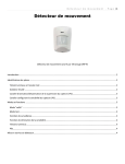
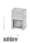

![mode d`emploi Stûv 21 [fr]](http://vs1.manualzilla.com/store/data/006519572_1-777a63b6c84e47bdf10842aa121225d5-150x150.png)

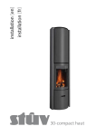


![notice d`installation Stûv 21 [fr]](http://vs1.manualzilla.com/store/data/006493748_1-9dce1cd1ec24d309135ee56c55c7accb-150x150.png)


![mode d`emploi Stûv 30-up [fr]](http://vs1.manualzilla.com/store/data/006507480_1-8b4a9775c4d1dab3792250b058abc82a-150x150.png)
![installation & directions for use installation & mode d`emploi [ en ] [ fr ]](http://vs1.manualzilla.com/store/data/006516414_1-826c39eefa343060f035675bc430e123-150x150.png)

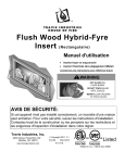
![mode d`emploi Stûv 30 [fr]](http://vs1.manualzilla.com/store/data/006452295_1-f2f8358be28b0bf58ee1c293eec3c700-150x150.png)