1
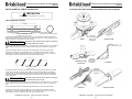
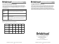
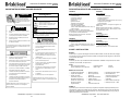
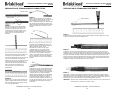
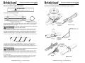
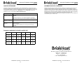
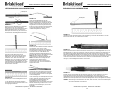
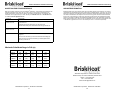
FE-Series Heating Cable Installation Instructions IMPORTANT SAFETY INSTRUCTIONS A person who has not read and understood all operating Instructions is not qualified to operate this product. Ordinary Locations Hazardous Locations Class I, Division 2, Groups B, C, & D Class II, Division 2, Groups F & G Class III, Division 2 DANGER Do not immerse heater in liquid. Heating sets must be 13mm (5/8”) from any combustible material. End-User Must Comply to the Following: Approvals valid only when installed in accordance with Keep sharp metal objects away from heater. WARNING Ordinary Locations (120 and 230VAC only) Use heater only in approved locations. Failure to observe these warnings may result in electric shock, risk of fire, and personal injury. CONNECTION / TERMINATION KIT DESCRIPTIONS Agency Approvals DANGER Only qualified personnel are allowed to connect the electrical wiring. Disconnect all supply power at the source before making any heating cable power input connections. CAUTION All electrical wiring must follow local electrical codes and highly recommend following NEC Article 427. The person who performs the final installation / wiring must be qualified for this work. The end-user is responsible for providing a suitable disconnecting device. The end-user is responsible for providing suitable electrical protection device. It is highly recommended that a ground fault circuit breaker be used. Failure to observe these warnings may result in personal injury or damage to the heater. FE-Series Heating Cable Installation Instructions Never handle the heater while it is in operation; always disconnect the heater from the power source and allow to cool prior to handling. Inspect heater and connection kits before use. Never operate heater without a temperature control device. FECABUC: FECABSK: Universal Connection/Termination Kit. 1-1” NPT Pipe standoff 2-Ring terminals 3-Wire nuts 2-Crimp barrels 3-Lead pouches 2-End pouches 1-Caution label 6-Shrink tubes 1-Panhead screw 1-3 oz. tube RTV sealant 2-Pipe straps Enough to complete: Two end terminations and one power input connection, or one power input splice. Splice Kit. 3-Lead pouches 3-Shrink tubes 3-Crimp barrels 3-Ring terminals 1-3 oz. tube RTV sealant 1-Caution label 1-End pouch Enough to complete: One in-line splice or one tee splice. Additional Required Hardware: Double hub junction box. FECABKC: Lead/ End Termination Kit 5-Lead pouches 5-End pouches 1-3 oz. tube RTV sealant Enough to complete: Five lead and end terminations. Additional Required Hardware: Wire nuts, pipe standoff, pipe straps, single hub junction box. FECABLP: Lead Termination Kit. 1-Lead pouch 1-Shrink tube Enough to complete: One lead termination. FECABEP: End Termination Kit. 1-End pouch 1-Shrink tube Enough to complete: One end termination. Do not wrap the heating cable over itself. If spillage of foreign matter onto heater occurs, disconnect from power source and clean after heater is allowed to cool. PRIOR TO INSTALLATION Never operate a heater without an appropriate heat sink (device being heated is considered a heat sink). Check for suspected damage to heater like rips, punctures, etc. Ensure surface to be heated is free of jagged or sharp edges or weld splatter. Do not operate heater above rated temperature value. Fasten heater to device using approved methods only. Do not repair damaged or faulty heaters. Do not crush or apply severe physical stress on heater or cord assembly. Disconnect heater when not in use. Failure to observe these warnings may result in personal injury or damage to the heater. STEP 1: STEP 2: Confirm all necessary installation hardware and tools are readily available. Depending on the application and kit, this may include. Tools Diagonal Cutter Measuring Tape/Ruler Crimping Tool / Wire Stripper Knife Heat Gun Screwdriver Hardware and Accessories Temperature Controller Insulating Material Caution Labels Temperature Sensor Monitor Light Kit (Optional) Aluminum or Fiberglass Connection / Termination Kits RTV Sealant Adhesive Tape (verify temperature rating) Heat Conductive Putty Pipe Standoffs 1” NPT (see kit descriptions to verify contents and additional required hardware) Pipe Straps Junction Box 1” NPT Wire Nuts STEP 3: (A) Verify the total amperage of the system does not exceed the maximum amperage that the heating system components can handle. (B) Verify that the total length of cable required does not exceed the maximum circuit length. If the cable length exceeds (A) or (B), the cable must be divided into sections. © BriskHeat® Corporation. All rights reserved. 3 © BriskHeat® Corporation. All rights reserved. 4