1
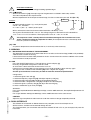
Vs (V)
Vs (V)
, the symmetry’setting knob
Vs (V)
50% / 50%
20% / 80%
Ton
80% / 20%
Toff
Ton
Ton
Period
Period
0
Time (s)
0
Toff
Period
Time (s)
0
Time (s)
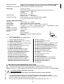
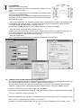
[12] SETTING OF THE OFFSET IN THE 50 Ω OUTPUT «OFFSET/CMOS»
The led [13] flashes to indicate the setting of the offset is on. The display [3] shows the DC voltage of the signal.
The tumbwheel switch [11] allows the setting of the offset. The 3 steps (big, medium, fine) of adjustment [19]
can be used to do a finest setting (switch [18]).
A second pressure in the switch of the offset reset it at 0Vdc. If you do another setting while the offset is diferent
from 0Vdc, the led [13] lights up. The setting allows to bring to the alternative signal a continuous voltage
adjustable between -10 to +10 Volts in open circuit.
This voltage is completely independent of the fixed [14] and variable [16] attenuators.
COMMENTS :
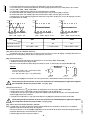
The output peak voltage of the amplifier is ± 10V. The amplifier reaches the saturation point at ± 11V.In order
to obtain an accurate output signal, it is necessary not to exceed 10V as absolute value (offset + signal).
The output impedance of the GF467F/AF is 50Ω. If this output has a 50Ω load, internal resistance and load make
a divider by 2 : the voltage range will be from -5V to +5V.
Time (s)
Vs (V)
Vs (V)
+11V
+10V
+5V
-11V
0
Offset + signal
> -10V (saturation)
Vs (V)
Time (s)
0
Time (s)
Offset + signal
> +10V (saturation)
Offset + signal < ±10V
(no saturation)
COMPLEMENTARY FUNCTION CMOS :
Reminder : ‘’Cmos’’ is a function that allows to couple systematicaly the setting of level and the offset in order
to obtain an output signal ever positive between 0 and 0........+10V.
Start : a long push in the switch Offset [12] untill it indicates «ON»
Deactivation : idem until it indicates «OFF»
CAUTION : The offset generated by the function Cmos must be manually rebooted when the mode will be exit.
Nota : when the function Cmos is activated, the setting of the offset is not available.
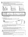
Signals Example :
Vs (V)
Square wave : 0 +10V
Vs (V)
+10V
+10V
4000 4 333-Evo1 - EN - 02/08
Vs (V)
+10V
Triangle wave : 0 +5V
Sine wave : 0 +1V
+5V
+5V
+1V
0
Time (s)
0
Time (s)
0
Time (s)
[15] SEETING OF THE LEVEL AND THE ATTENUATORS (LEVEL)
A push on [15] allows the setting of of the offset by the thumbwheel switch [11]. The led [16] flashes to indicate
that the mode setting LEVEL is activated. The selector [18] activating [19] «Coarse, Med, Fine» can be used
to make a finest adjust.
- 21 -
ENGLISH
Use of cyclic ratio with sine signals
When the warning [10] is flashing and the warning [8] is in the sine position
modifies the sine signals as indicated below :