1
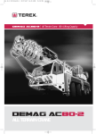
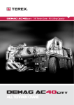
AC 80-2
Demag AC 80-2
Shortest 4-axle machine in its category
Advanced high-torque DaimlerChrysler
engine combined with comfortable 6-speed
Allison automatic transmission ensures
outstanding driving performance
Fully hydraulic boom system for exceptionally short telescoping times and high
load telescoping capacity
Fully roadable with 8 t counterweight and
9.2 m boom extension within the statutory
12 t axle load limit
New tiltable upper cab
New high-spec carrier cab
ABS, heated seats and electric window
winders included as standard
Kürzester 4-Achser seiner Klasse
Hervorragende Fahreigenschaften durch
modernen drehmomentstarken
DaimlerChrysler-Motor in Verbindung mit
komfortablem 6-Gang Allison Automatikgetriebe
Kürzeste Teleskopierzeiten und hohe teleskopierbare Lasten durch vollhydraulisches
Auslegersystem
8 t Gegengewicht und Hauptauslegerverlängerung 9,2 m innerhalb der
12 t Achslastregelung verfahrbar
Neue neigbare Oberwagenkabine
Neue hochwertig ausgestattete Unterwagenkabine
ABS, Sitzheizung und elektrische Fensterheber serienmäßig
La 4 essieux la plus compacte de sa catégorie
Grand confort de conduite grâce à une
motorisation DaimlerChrysler moderne au
couple puissant associée à une boîte automatique Allison à 6 rapports
Temps de télescopage ultracourts et
d’énormes charges télescopables grâce au
système de flèche entièrement hydraulique
Déplacement sur route avec contrepoids
de 8 t et rallonge de 9,2 m dans le respect
du poids à l'essieu réglementaire de 12 t
Nouvelle cabine tourelle basculable
Nouvelle cabine châssis à l'équipement
haut de gamme
ABS, sièges chauffants et lève-vitres électriques de série
www. terex-cranes.com
AC 80-2
2
Contents
Inhalt
Contenu
Page · Seite:
Specifications · Technische Daten · Caractéristiques
4
6
1
7
8
2
Lifting capacities · Tragfähigkeiten · Capacités de levage . . . . . . . . . . . . . . . . . . . . . . . . . . . . . . . . . . . . . . . . . . . . . . . . . . . . . . . . . . . . . . . 10
Working ranges · Arbeitsbereiche · Portées . . . . . . . . . . . . . . . . . . . . . . . . . . . . . . . . . . . . . . . . . . . . . . . . . . . . . . . . . . . . . . . . . . . . . . . . . . 12
3
Dimensions · Abmessungen · Encombrement . . . . . . . . . . . . . . . . . . . . . . . . . . . . . . . . . . . . . . . . . . . . . . . . . . . . . . . . . . . . . . . . . . . . . . . .
Specifications · Technische Daten · Caractéristiques . . . . . . . . . . . . . . . . . . . . . . . . . . . . . . . . . . . . . . . . . . . . . . . . . . . . . . . . . . . . . . . . . . . .
Main boom · Hauptausleger · Flèche principale
Working ranges · Arbeitsbereiche · Portées . . . . . . . . . . . . . . . . . . . . . . . . . . . . . . . . . . . . . . . . . . . . . . . . . . . . . . . . . . . . . . . . . . . . . . . . . .
Lifting capacities · Tragfähigkeiten · Capacités de levage . . . . . . . . . . . . . . . . . . . . . . . . . . . . . . . . . . . . . . . . . . . . . . . . . . . . . . . . . . . . . . .
Main boom extension · Hauptauslegerverlängerung · Rallonge de flèche
Technical description · Technische Beschreibung · Descriptif technique
Carrier · Superstructure · Optional equipment . . . . . . . . . . . . . . . . . . . . . . . . . . . . . . . . . . . . . . . . . . . . . . . . . . . . . . . . . . . . . . . . . . . . . . . 14
Unterwagen · Oberwagen · Zusatzausrüstung . . . . . . . . . . . . . . . . . . . . . . . . . . . . . . . . . . . . . . . . . . . . . . . . . . . . . . . . . . . . . . . . . . . . . . . 15
Châssis · Partie supérieure · Equipements optionnels . . . . . . . . . . . . . . . . . . . . . . . . . . . . . . . . . . . . . . . . . . . . . . . . . . . . . . . . . . . . . . . . . . 16
4
Overview of standard duty charts
Übersicht Standard-Tragfähigkeitstabellen · Tableau synoptique des abaques standard . . . . . . . . . . . . . . . . . . . . . . . . . . . . . . . . . . . . . . 17
AC 80-2
3
5
Dimensions
Abmessungen
Encombrement
AC 80-2
4
1
( ) with independent rear axle steering
( ) mit unabhängiger Hinterachslenkung
( ) avec direction indépendante de l’essieu arrière
1)
Option
AC 80-2
5
Specifications
Technische Daten
Caractéristiques
Axle loads · Achslasten · Poids d’essieux
Crane with main boom, hook block 3-sheave, 8 t counterweight, tyres 14.00 R 25 · Kran mit Hauptausleger, Unterflasche 3-rollig,
8 t Gegengewicht, Bereifung 14.00 R 25 · Grue avec flèche principale, crochet-moufle 3 poulies, 8 t de contrepoids, pneumatiques
14.00 R 25.
Axles · Achsen · Essieux
4 x 12 000 kg
Total · Gesamt · Total
48 000 kg
Working speeds (infinitely variable) · Arbeitsgeschwindigkeiten (stufenlos regelbar)
Vitesses de travail (réglables sans paliers)
Mechanisms
Antriebe
Mécanismes
Normal speed
Normalgang
Marche normale
High speed
Schnellgang
Marche rapide
Max. permissible line pull 1)
Max. zulässiger Seilzug 1)
Effort max. admis sur câble 1)
Rope diameter / Rope length
Seil ø / Seillänge
Diamètre du câble / Longueur du câble
Hoist I
Hubwerk I
Treuil II
53 m / min
110 m / min
55 kN
18 mm / 210 m
Hoist II
Hubwerk II
Treuil II
53 m / min
110 m / min
55 kN
18 mm / 210 m
Slewing · Drehwerk · Orientation
max. 1,3 1/min
Telescoping speed · Ausleger-Teleskopieren · Vitesse de télescopage
10,9 – 50 m: 110 s
Boom elevation · Ausleger-Winkelverstellung · Relevage de flèche
–1,8° – +81,5°: 63 s
Carrier performance · Fahrleistungen · Performance du porteur
Travel speed · Fahrgeschwindigkeit · Vitesse sur route
Forward · Vorwärts · Avant
Reverse · Rückwärts · Arrière
Gradeability in travel order · Steigfähigkeit bei Transportgewicht · Capacité sur rampes en état de transport sur route
Ground clearance · Bodenfreiheit · Dégagement au sol
0 . . 80 km/h
0 . . 11 km/h
max. 50%
370 mm
Hook block / Single line hook · Unterflasche / Hakengehänge · Crochet-moufle / Boulet
Type
Typ
Type
Possible load 1)
mögliche Traglast 1)
Charge possible 1)
Number of sheaves
Anzahl der Rollen
Nombre de poulies
Weight
Gewicht
Poids
100
180
150
120
116,3
77,0 t
60,5 t
38,5 t
16,5 t
5,5 t
7
5
3
1
Single line hook/
Hakengehänge/
Boulet
750 kg
650 kg
550 kg
350 kg
170 kg
„D“
2,00 m
2,00 m
1,80 m
1,80 m
1,70 m
max. reeving
Heavy-lift attachment
max. Einscherung Schwerlasteinrichtung
mouflage maxi
Equipement levage lourd
14
11
7
3
1
2 add. sheaves/Zusatzrollen/poulies suppl.
2 add. sheaves/Zusatzrollen/poulies suppl.
Remarks · Bemerkungen · Remarques
1)
1)
1)
varies depending on national regulations
variiert je nach Ländervorschrift
varie en fonction des normes nationales
AC 80-2
6
Working ranges main boom
Arbeitsbereiche Hauptausleger
Portées flèche principale
AC 80-2
7
Lifting capacities main boom
Tragfähigkeiten Hauptausleger
Capacités de levage flèche principale
18 t
Radius
Ausladung
Portée
1m
13
13
13,5
14
14,5
15
16
17
18
19
10
12
14
16
18
20
22
24
26
28
30
32
34
36
38
40
42
44
46
7,70 m x 7,00 m
Main boom · Hauptausleger · Flèche principale
m
10,9
t,0
80,0 *
70,0
64,4
59,3
54,9
51,0
42,0
35,0
28,3
-,0
-,0
-,0
-,0
-,0
-,0
-,0
-,0
-,0
-,0
-,0
-,0
-,0
-,0
-,0
-,0
-,0
-,0
-,0
-,0
16,1
t,0
-,0
-,0
55,0
55,0
52,9
49,6
41,7
34,8
29,6
25,6
22,1
16,1
-,0
-,0
-,0
-,0
-,0
-,0
-,0
-,0
-,0
-,0
-,0
-,0
-,0
-,0
-,0
-,0
-,0
21,4
t,0
-,0
-,0
-,0
45,0
43,0
41,0
36,5
32,0
28,0
24,8
21,0
15,8
13,8
11,2
9,2
-,0
-,0
-,0
-,0
-,0
-,0
-,0
-,0
-,0
-,0
-,0
-,0
-,0
-,0
8t
Radius
Ausladung
Portée
1m
13
13
13,5
14
14,5
15
16
17
18
19
10
12
14
16
18
20
22
24
26
28
30
32
34
36
38
DIN/ISO
360°
25,0
t,0
-,0
-,0
-,0
-,0
32,0
32,0
31,0
29,0
26,0
23,5
21,0
16,8
13,3
10,7
8,7
7,2
-,0
-,0
-,0
-,0
-,0
-,0
-,0
-,0
-,0
-,0
-,0
-,0
-,0
31,3
t,0
-,0
-,0
-,0
-,0
-,0
20,0
20,0
20,0
20,0
19,5
18,5
16,1
12,8
10,2
8,2
7,0
6,4
5,8
5,2
-,0
-,0
-,0
-,0
-,0
-,0
-,0
-,0
-,0
-,0
37,1
t,0
-,0
-,0
-,0
-,0
-,0
-,0
16,0
15,5
15,0
14,5
14,0
12,7
11,3
10,0
8,5
7,4
6,3
5,8
5,2
4,5
3,9
3,4
-,0
-,0
-,0
-,0
-,0
-,0
-,0
7,70 m x 7,00 m
42,3
t,0
-,0
-,0
-,0
-,0
-,0
-,0
-,0
13,0
13,0
12,9
12,7
11,8
10,9
10,0
8,8
7,3
6,4
5,4
4,5
4,0
3,7
3,3
2,8
2,4
2,1
-,0
-,0
-,0
-,0
46,1
t,0
-,0
-,0
-,0
-,0
-,0
-,0
-,0
-,0
8,8
8,8
8,8
8,8
8,5
8,0
7,5
7,0
6,3
5,3
4,7
4,0
3,4
2,9
2,4
2,0
1,7
1,3
1,0
-,0
-,0
50,0
t,0
-,0
-,0
-,0
-,0
-,0
-,0
-,0
-,0
-,0
6,5
6,5
6,5
6,5
6,5
6,2
5,9
5,5
5,1
4,4
3,7
3,1
2,6
2,1
1,7
1,4
1,1
0,7
-,0
-,0
10,9
t,0
-,0
-,0
-,0
12,3
11,0
9,9
8,1
6,6
5,5
-,0
-,0
-,0
-,0
-,0
-,0
-,0
-,0
-,0
-,0
-,0
-,0
-,0
-,0
-,0
-,0
-,0
-,0
-,0
-,0
16,1
t,0
-,0
-,0
-,0
12,0
10,7
9,6
7,8
6,4
5,2
4,2
3,4
2,1
-,0
-,0
-,0
-,0
-,0
-,0
-,0
-,0
-,0
-,0
-,0
-,0
-,0
-,0
-,0
-,0
-,0
DIN/ISO
360°
Main boom · Hauptausleger · Flèche principale
m
10,9
t,0
80,0 *
70,0
64,1
59,0
52,9
46,7
37,6
31,3
24,2
-,0
-,0
-,0
-,0
-,0
-,0
-,0
-,0
-,0
-,0
-,0
-,0
-,0
-,0
-,0
-,0
16,1
t,0
-,0
-,0
55,0
55,0
52,6
46,4
37,3
31,0
23,7
18,9
15,5
11,0
-,0
-,0
-,0
-,0
-,0
-,0
-,0
-,0
-,0
-,0
-,0
-,0
-,0
21,4
t,0
-,0
-,0
-,0
45,0
43,0
41,0
34,9
27,4
22,3
18,0
17,3
12,7
9,6
7,5
6,0
-,0
-,0
-,0
-,0
-,0
-,0
-,0
-,0
-,0
-,0
25,0
t,0
-,0
-,0
-,0
-,0
32,0
32,0
31,0
25,7
21,0
19,0
16,8
12,1
9,0
7,0
5,4
4,2
-,0
-,0
-,0
-,0
-,0
-,0
-,0
-,0
-,0
31,3
t,0
-,0
-,0
-,0
-,0
-,0
20,0
20,0
20,0
20,0
18,1
15,5
11,5
9,3
8,1
6,5
5,4
4,4
3,6
3,0
-,0
-,0
-,0
-,0
-,0
-,0
37,1
t,0
-,0
-,0
-,0
-,0
-,0
-,0
16,0
15,5
15,0
14,5
14,0
11,5
9,3
8,1
6,5
5,3
4,4
3,6
2,9
2,4
1,9
1,6
-,0
-,0
-,0
42,3
t,0
-,0
-,0
-,0
-,0
-,0
-,0
-,0
13,0
13,0
12,9
12,7
11,1
9,0
7,4
5,9
5,1
4,3
3,5
2,9
2,3
1,9
1,5
1,2
0,9
0,6
Radius
Ausladung
Portée
1m
13
13
13,5
14
14,5
15
16
17
18
19
10
12
14
16
18
20
22
24
26
28
30
32
34
36
38
40
42
44
46
46,1
t,0
-,0
-,0
-,0
-,0
-,0
-,0
-,0
-,0
8,8
8,8
8,8
8,8
8,5
7,1
6,1
4,8
3,9
3,1
2,4
1,9
1,4
1,1
0,7
-,0
-,0
50,0
t,0
-,0
-,0
-,0
-,0
-,0
-,0
-,0
-,0
-,0
6,5
6,5
6,5
6,5
6,5
5,6
4,5
3,6
2,8
2,1
1,6
1,2
0,8
-,0
-,0
-,0
10,9
t,0
-,0
-,0
-,0
11,7
10,4
9,4
7,6
6,2
5,1
-,0
-,0
-,0
-,0
-,0
-,0
-,0
-,0
-,0
-,0
-,0
-,0
-,0
-,0
-,0
-,0
16,1
t,0
-,0
-,0
-,0
11,4
10,2
9,1
7,4
6,0
4,8
3,9
3,1
1,9
-,0
-,0
-,0
-,0
-,0
-,0
-,0
-,0
-,0
-,0
-,0
-,0
-,0
Radius
Ausladung
Portée
1m
13
13
13,5
14
14,5
15
16
17
18
19
10
12
14
16
18
20
22
24
26
28
30
32
34
36
38
Remarks · Bemerkungen · Remarques
* over rear
* nach hinten
* sur l’arrière
AC 80-2
8
5t
Radius
Ausladung
Portée
1m
13
13,5
14
14,5
15
16
17
18
19
10
12
14
16
18
20
22
24
26
28
30
32
34
36
7,70 m x 7,00 m
DIN/ISO
360°
Main boom · Hauptausleger · Flèche principale
m
10,9
t,0
70,0
64,1
58,7
51,1
45,1
36,3
28,0
21,4
-,0
-,0
-,0
-,0
-,0
-,0
-,0
-,0
-,0
-,0
-,0
-,0
-,0
-,0
-,0
16,1
t,0
-,0
55,0
55,0
50,8
44,8
36,0
27,6
21,0
16,7
13,5
9,3
-,0
-,0
-,0
-,0
-,0
-,0
-,0
-,0
-,0
-,0
-,0
-,0
21,4
t,0
-,0
-,0
45,0
43,0
41,0
30,9
24,2
19,5
18,0
15,5
11,0
8,2
6,4
5,0
-,0
-,0
-,0
-,0
-,0
-,0
-,0
-,0
-,0
25,0
t,0
-,0
-,0
-,0
32,0
32,0
28,7
22,6
19,0
17,9
14,9
10,4
7,7
5,8
4,4
3,3
-,0
-,0
-,0
-,0
-,0
-,0
-,0
-,0
31,3
t,0
-,0
-,0
-,0
-,0
20,0
20,0
20,0
18,8
15,7
13,3
10,5
8,9
7,0
5,6
4,5
3,6
2,9
2,3
-,0
-,0
-,0
-,0
-,0
37,1
t,0
-,0
-,0
-,0
-,0
-,0
16,0
15,5
15,0
14,4
12,9
10,2
8,9
6,9
5,5
4,4
3,5
2,8
2,3
1,8
1,4
1,0
-,0
-,0
42,3
t,0
-,0
-,0
-,0
-,0
-,0
-,0
13,0
13,0
12,9
12,5
9,9
7,8
6,2
5,5
4,4
3,5
2,8
2,2
1,7
1,3
1,0
0,7
-,0
46,1
t,0
-,0
-,0
-,0
-,0
-,0
-,0
-,0
8,8
8,8
8,8
8,8
7,4
6,2
5,0
3,9
3,0
2,3
1,8
1,3
0,9
-,0
-,0
-,0
50,0
t,0
-,0
-,0
-,0
-,0
-,0
-,0
-,0
-,0
6,5
6,5
6,5
6,5
5,7
4,6
3,6
2,7
2,0
1,5
1,0
0,6
-,0
-,0
-,0
10,9
t,0
-,0
-,0
11,5
10,3
9,2
7,5
6,1
5,0
-,0
-,0
-,0
-,0
-,0
-,0
-,0
-,0
-,0
-,0
-,0
-,0
-,0
-,0
-,0
16,1
t,0
-,0
-,0
11,2
10,0
9,0
7,2
5,8
4,7
3,8
3,0
1,6
-,0
-,0
-,0
-,0
-,0
-,0
-,0
-,0
-,0
-,0
-,0
-,0
Radius
Ausladung
Portée
1m
13
13,5
14
14,5
15
16
17
18
19
10
12
14
16
18
20
22
24
26
28
30
32
34
36
AC 80-2
9
2
Lifting capacities main boom extension
Tragfähigkeiten Hauptauslegerverlängerung
Capacités de levage rallonge de flèche
18 t
7,70 x 7,00 m
360°
DIN/ISO 8 t
46,1 m
Main boom · Hauptausleger · Flèche principale
Extension · Verlängerung · Rallonge
Radius
9,2 m
17,6 m
Ausladung
Portée
0°
20°
40°
0°
20°
t,0
t,0
t,0
1m
t,0
t,0
-,0
-,0
-,0
10
3,9
-,0
-,0
12
3,9
1,7
-,0
-,0
3,4
14
3,9
1,7
-,0
-,0
3,4
16
3,9
3,0
1,7
-,0
3,3
18
3,9
3,0
1,7
1,4
3,2
20
3,7
2,9
1,6
1,4
3,1
22
3,5
2,8
1,5
1,4
2,9
24
3,3
2,7
1,5
1,4
2,8
26
3,1
2,6
1,4
1,4
28
3,0
2,6
2,5
1,4
1,4
30
2,8
2,4
2,5
1,3
1,3
32
2,7
2,3
2,4
1,3
1,2
34
2,4
2,2
2,3
1,2
1,1
36
2,0
2,1
2,2
1,2
1,1
38
1,6
1,9
1,8
1,1
1,1
40
1,3
1,6
1,5
1,1
1,1
42
1,0
-,0
1,2
1,1
1,1
44
0,8
-,0
0,9
1,0
1,1
46
-,0
-,0
0,6
0,8
1,1
48
-,0
-,0
-,0
0,6
0,8
50
-,0
-,0
-,0
-,0
0,6
50,0 m
12
14
16
18
20
22
24
26
28
30
32
34
36
38
40
42
44
46
48
50
40°
t,0
-,0
-,0
-,0
-,0
-,0
-,0
-,0
1,2
1,1
1,1
1,1
1,1
1,1
1,1
1,0
1,0
1,0
1,0
1,0
1,0
-,0
Main boom · Hauptausleger · Flèche principale
3,0
3,0
3,0
3,0
2,9
2,8
2,6
2,5
2,3
2,2
2,1
2,0
1,9
1,5
1,2
0,9
0,7
-,0
-,0
-,0
-,0
3,0
3,0
2,9
2,8
2,7
2,5
2,4
2,2
2,1
2,0
1,9
1,8
1,8
1,4
1,1
0,9
0,6
-,0
-,0
-,0
-,0
2,7
2,7
2,6
2,5
2,3
2,2
2,1
2,0
1,9
1,9
1,8
1,8
1,6
-,0
-,0
-,0
-,0
-,0
-,0
1,2
1,2
1,2
1,2
1,1
1,1
1,0
1,0
1,0
1,0
0,9
0,9
0,9
0,8
0,8
0,7
0,7
-,0
-,0
-,0
-,0
-,0
-,0
1,1
1,1
1,1
1,1
1,0
1,0
1,0
1,0
0,9
0,9
0,9
0,9
0,8
0,8
0,8
0,6
360°
DIN/ISO
46,1 m
Main boom · Hauptausleger · Flèche principale
Extension · Verlängerung · Rallonge
Radius
9,2 m
17,6 m
Ausladung
Portée
0°
20°
40°
0°
20°
t,0
t,0
1m
t,0
t,0
t,0
-,0
-,0
10
3,9
-,0
-,0
-,0
12
3,9
1,7
-,0
-,0
3,4
14
3,9
1,7
-,0
-,0
3,4
16
3,9
1,7
3,0
-,0
3,3
18
3,9
1,7
3,0
1,4
3,2
20
3,7
1,6
2,9
1,4
22
3,5
3,1
2,8
1,5
1,4
24
3,1
2,9
2,7
1,5
1,4
26
2,4
2,8
2,6
1,4
1,4
28
1,9
2,3
2,5
1,4
1,4
30
1,4
2,0
1,8
1,3
1,3
32
1,0
1,5
1,3
1,3
1,2
34
0,7
1,1
1,0
1,0
1,1
36
-,0
0,8
0,6
0,7
1,1
38
-,0
-,0
-,0
-,0
0,8
40
-,0
-,0
-,0
-,0
0,6
42
-,0
-,0
-,0
-,0
-,0
44
-,0
-,0
-,0
-,0
-,0
46
-,0
-,0
-,0
-,0
-,0
48
-,0
-,0
-,0
-,0
-,0
50
-,0
-,0
-,0
-,0
-,0
50,0 m
-,0
-,0
-,0
-,0
-,0
-,0
1,0
1,0
1,0
1,0
1,0
1,0
0,9
0,9
0,9
0,9
0,9
0,8
0,8
-,0
7,70 x 7,00 m
12
14
16
18
20
22
24
26
28
30
32
34
36
38
40
42
44
46
48
50
40°
t,0
-,0
-,0
-,0
-,0
-,0
-,0
-,0
1,2
1,1
1,1
1,1
1,1
1,1
1,1
1,0
0,9
0,6
-,0
-,0
-,0
-,0
Main boom · Hauptausleger · Flèche principale
3,0
3,0
3,0
3,0
2,9
2,8
2,6
2,4
1,8
1,4
1,0
0,6
-,0
-,0
-,0
-,0
-,0
-,0
-,0
-,0
-,0
3,0
3,0
2,9
2,8
2,7
2,5
2,4
2,2
1,7
1,3
0,9
0,6
-,0
-,0
-,0
-,0
-,0
-,0
-,0
-,0
-,0
2,7
2,7
2,6
2,5
2,3
2,2
2,1
2,0
1,5
1,1
0,8
-,0
-,0
-,0
-,0
-,0
-,0
-,0
-,0
1,2
1,2
1,2
1,2
1,1
1,1
1,0
1,0
1,0
1,0
0,9
0,6
-,0
-,0
-,0
-,0
-,0
-,0
-,0
-,0
-,0
-,0
-,0
1,1
1,1
1,1
1,1
1,0
1,0
1,0
1,0
0,9
0,8
-,0
-,0
-,0
-,0
-,0
-,0
-,0
-,0
-,0
-,0
-,0
-,0
1,0
1,0
1,0
1,0
1,0
1,0
0,9
0,9
0,8
-,0
-,0
-,0
-,0
-,0
AC 80-2
10
5t
7,70 x 7,00 m
360°
DIN/ISO
46,1 m
Main boom · Hauptausleger · Flèche principale
Extension · Verlängerung · Rallonge
Radius
9,2 m
17,6 m
Ausladung
Portée
0°
20°
40°
0°
20°
t,0
t,0
1m
t,0
t,0
t,0
-,0
-,0
-,0
10
3,9
-,0
-,0
12
3,9
1,7
-,0
-,0
3,4
14
3,9
1,7
-,0
-,0
3,4
16
3,9
3,0
1,7
-,0
3,3
18
3,9
3,0
1,7
1,4
20
3,7
3,2
2,9
1,6
1,4
22
3,1
3,1
2,8
1,5
1,4
24
2,3
2,7
2,8
1,5
1,4
26
1,8
2,5
2,2
1,4
1,4
28
1,3
1,9
1,7
1,4
1,4
30
0,8
1,4
1,2
1,1
1,3
32
-,0
1,0
0,8
0,8
1,2
34
-,0
0,6
-,0
-,0
1,0
36
-,0
-,0
-,0
-,0
0,7
38
-,0
-,0
-,0
-,0
-,0
50,0 m
12
14
16
18
20
22
24
26
28
30
32
34
36
38
40°
t,0
-,0
-,0
-,0
-,0
-,0
-,0
-,0
1,2
1,1
1,1
1,1
1,1
1,1
1,1
0,8
3
Main boom · Hauptausleger · Flèche principale
3,0
3,0
3,0
3,0
2,9
2,8
2,2
1,7
1,2
0,8
-,0
-,0
-,0
-,0
-,0
3,0
3,0
2,9
2,8
2,7
2,5
2,1
1,6
1,2
0,8
-,0
-,0
-,0
-,0
-,0
2,7
2,7
2,6
2,5
2,3
2,2
1,9
1,4
1,0
0,6
-,0
-,0
-,0
1,2
1,2
1,2
1,2
1,1
1,1
1,0
1,0
1,0
0,6
-,0
-,0
-,0
-,0
-,0
-,0
-,0
1,1
1,1
1,1
1,1
1,0
1,0
1,0
0,9
0,6
-,0
-,0
-,0
-,0
-,0
-,0
-,0
1,0
1,0
1,0
1,0
1,0
1,0
0,9
0,7
AC 80-2
11
Working ranges main boom extension
Arbeitsbereiche Hauptauslegerverlängerung
Portées rallonge de flèche
AC 80-2
12
Notes to lifting capacity
Anmerkungen zu den Tragfähigkeiten
Conditions d’utilisation
Ratings are in compliance with ISO 4305 and DIN 15019.2 (test load = 1.25 x suspended load + 0.1 x dead weight of boom reduced
to boom point).
Weight of hook blocks and slings is part of the load, and is to be deducted from the capacity ratings.
Crane operation is permissible up to a
wind pressure of . . . . . . . . . . . . . . . . . . . . . . . . . . . . . . . . . . . . . . . . . . . . . . . . . . . . . . . . . . . . . . . . . . . . . . . . . . . . . . . . . . . . . . . . .
60 N/m2
wind speed of . . . . . . . . . . . . . . . . . . . . . . . . . . . . . . . . . . . . . . . . . . . . . . . . . . . . . . . . . . . . . . . . . . . . . . . . . . . . . . . . . . . . . . . . . . .
9.8 m/s
Consult operation manual for further details.
Note: Data published herein is intended as a guide only and shall not be construed to warrant applicability for lifting purposes.
Crane operation is subject to the computer charts and operation manual both supplied with the crane.
Tragfähigkeiten entsprechen ISO 4305 und DIN 15019.2 (Prüflast = 1,25 x Hublast + 0,1 x Auslegereigengewicht, auf die Auslegerspitze
reduziert).
Das Gewicht der Unterflaschen sowie die Lastaufnahmemittel sind Bestandteile der Last und von den Tragfähigkeitsangaben
abzuziehen.
Kranbetrieb zulässig bis
Staudruck . . . . . . . . . . . . . . . . . . . . . . . . . . . . . . . . . . . . . . . . . . . . . . . . . . . . . . . . . . . . . . . . . . . . . . . . . . . . . . . . . . . . . . . . . . . . . .
60 N/m2
Windgeschwindigkeit . . . . . . . . . . . . . . . . . . . . . . . . . . . . . . . . . . . . . . . . . . . . . . . . . . . . . . . . . . . . . . . . . . . . . . . . . . . . . . . . . . . . .
9,8 m/s
Weitere Angaben in der Bedienungsanleitung des Kranes.
Anmerkung: Die Daten dieser Broschüre dienen nur zur allgemeinen Information; für ihre Richtigkeit übernehmen wir keine Haftung.
Der Betrieb des Kranes ist nur mit den Original-Tragfähigkeitstabellen und mit der Bedienungsanleitung zulässig, die mit dem Kran
mitgeliefert werden.
Le tableau de charges est conforme à la norme ISO 4305 et DIN 15019.2 (charge d’essai = 1,25 x charge suspendue + 0,1 x poids
de la flèche réduit à la pointe de flèche).
Les poids du crochet-moufle et de tous les accessoires d’élingage font partie de la charge et sont à déduire des charges indiquées.
La grue peut travailler jusqu’à une
pression du vent de . . . . . . . . . . . . . . . . . . . . . . . . . . . . . . . . . . . . . . . . . . . . . . . . . . . . . . . . . . . . . . . . . . . . . . . . . . . . . . . . . . . . . .
60 N/m2
vitesse du vent de . . . . . . . . . . . . . . . . . . . . . . . . . . . . . . . . . . . . . . . . . . . . . . . . . . . . . . . . . . . . . . . . . . . . . . . . . . . . . . . . . . . . . . . .
9,8 m/s
Pour plus de détails consulter la notice d’utilisation de la grue.
Nota: Les renseignements ci-inclus sont donnés à titre indicatif et ne représentent aucune garantie d’utilisation pour les opérations
de levage. La mise en service de la grue n’est autorisée qu’à condition que les tableaux de charges ainsi que le manuel de service,
tels que fournis avec la grue, soient observés.
AC 80-2
13
Technical description
Carrier
Drive / steering
Frame
Outriggers
Engine
Transmission
Axles
Suspension
Wheels and tyres
Steering
Brakes
Travel speed
Electrical equipment
2-man driver’s cab
8 x 6 x 6.
Monobox main frame with outrigger boxes integral, of high-strength fine-grain structural steel.
Four hydraulically telescoping outrigger beams with hydraulic jack legs.
Water-cooled 6 cylinder DaimlerChrysler engine OM 501 LA, output to DIN: 315 kW (428 hp)
at 1800 1/min, max. torque 2000 Nm at 1080 1/min, certified in compliance with EURO MOT 2, EPA 2,
CARB, stainless steel exhaust system with spark arrestor. Tank capacity: 400 l.
Allison automatic transmission, transfer case with off-road range.
1st: steering. 2nd: steering. 3rd: rigid, non-steering, 4th: steering. Axles 1, 2 and 4 with planetary hubs.
Differential lock-out control on 2nd axle: longitudinal and transverse. 1st and 4th axle: transverse.
Hydropneumatic suspension, all axles hydraulically blockable.
8 x 14.00 R 25 on 11.25-25 rims; tubeless road-tread tyres. All axles single-wheeled.
Dual-circuit semiblock mechanical steering with hydraulic booster.
Service brake: dual-line air system with ABS, acting on all wheels. Parking brake: spring-loaded type.
Sustained action brake: engine exhaust brake and constant decompression valve, automatic downhill
brake control.
80 km/h, brake control.
24 V.
Rubber-mounted steel cab with safety glass, carrier controls, air-sprung and heated driver’s and passenger
seat with integrated seat belts, height and tilt adjustable steering wheel, electric window winders,
electrically adjustable and heated outside mirrors, cruise control, radio with CD-player, rotary beacon.
Superstructure
Hydraulic system
Hoist
Slew unit
Derricking unit
Crane cab
Main boom
Counterweight
Top steer facility
Safety devices
Hydraulic servo control
Driven off carrier engine at low revs, 1 variable-displacement axial piston pump and separate fixeddisplacement pump for 4 simultaneous, independent working movements.
Fixed-displacement axial-piston motor, hoist drum with planetary reduction integral and spring-applied
holding brake.
Hydraulic motor with planetary reduction, foot-pedal brake and spring-applied holding brake.
1 differential cylinder with pilot-controlled lowering brake valve.
Spacious all-steel comfortable cab with sliding door and large hinged windscreen, roof window with
armoured glass, controls and instrumentation for all crane movements, working lights, self-contained hot
water heater with timer, thermostat-controlled, windscreen washer and wiper with intermittent control,
cab tiltable up to 18°.
Boom base and 5 telescopic sections of fine-grain structural steel, telescoping with partial load, bucklingresistant Demag ovaloid design.
8 t in sections of 5.1 t, 1.7 t and 1.2 t (6.8 t fitted on superstructure, 1.2 t hydraulically stowed on carrier
deck).
Included as standard.
Electronic safe load indicator with digital read-out for hook load, rated load, boom length, boom angle,
load radius, analog display to indicate the capacity utilization. Limit switches on hoist and loweringmotions, pressure-relief and safety holding valves.
Hydraulic pilot control through self-centering control levers.
Optional equipment
Drive / steering
Tyres
Telma brake
Trailer coupling
Hoist II
8 x 8 x 8.
Optional 16.00 R 25, 17.5 R 25 or 20.5 R 25.
For central axle trailers with max. 24 t total weight and ABS air hookup: D = 190; DC = 155; V = 75.
Fixed displacement axial-piston motor, hoist drum with planetary reduction integral and spring-applied
holding brake. Hoist II avoids re-reeving of hoist line when using the optional jib.
1- or 2-part folding jib, 9.2 m or 17.6 m. 0°, 20° and 40° offset.
10 t, integrated into standard counterweight, installed hydraulically by the crane itself.
Additional sheaves on boom head for duties over 60 t.
1.20 m long, 1-sheave.
Main boom extension
Additional counterweight
Heavy-lift attachment
Heavy-lift runner
Outrigger loading indicator
Limitation of working range
Radio with CD-player
in upper cab
Stowing point for hook block For 1 and 3-sheave hook blocks or for 5-sheave hook block, for single line hook block.
Tackle box on the rear
of the carrier
AC 80-2
14
Technische Beschreibung
Unterwagen
Antrieb / Lenkung
Rahmen
Abstützung
Motor
Getriebe
Achsen
Federung
Bereifung
Lenkung
Bremsen
Fahrgeschwindigkeit
Elektrische Anlage
2-Mann-Fahrerkabine
8 x 6 x 6.
Geschlossenes Kastenprofil mit integrierten Abstützkästen aus hochfestem Feinkornbaustahl.
4-Punkt-Abstützung, hydraulisch horizontal und vertikal auszufahrende Abstützungen.
Wassergekühlter 6-Zylinder DaimlerChrysler Motor OM 501 LA, Leistung nach DIN: 315 kW (428 PS)
bei 1800 1/min, max. Drehmoment 2000 Nm bei 1080 1/min, Zertifizierung nach EURO MOT 2, EPA 2,
CARB, Edelstahl-Abgasanlage mit Funkenfänger. Inhalt des Kraftstoffbehälters: 400 l.
Allison Automatik-Getriebe, Verteilergetriebe mit Geländestufe.
Achse 1: Planetenachse, lenkbar, Querdifferentialsperre; Achse 2: Planetenachse, lenkbar, Längs- und
Querdifferentialsperre; Achse 3: starre Achse, nicht lenkbar; Achse 4: Planetenachse, lenkbar,
Querdifferentialsperre.
Hydropneumatische Federung, alle Achsen hydraulisch blockierbar.
8-fach, 14.00 R 25 auf Felge 11.25-25, Straßenprofil – schlauchlos, alle Achsen einfachbereift.
2-Kreis-Hydro-Halbblocklenkung.
Betriebsbremse: Zweikreis-Druckluft-Bremsanlage mit ABS, auf alle Räder wirkend. Feststellbremse:
Federspeicherbremse. Dauerbremse: Motorklappenbremse und Konstantdrossel, Dauerbrems-Tempomat.
80 km/h, Tempomat.
Betriebsspannung 24 V.
Elastisch gelagerte Fahrerkabine aus Stahlblech mit Sicherheitsverglasung, Betätigungsorganen, luftgefedertem und beheizbarem Fahrer- und Beifahrersitz mit Integralgurt, höhen- und neigungsverstellbarem Lenkrad, elektrischen Fensterhebern, elektrisch verstell- und beheizbaren Außenspiegeln,
Tempomat, Radio mit CD-Player, Rundumleuchte.
Oberwagen
Hydraulikanlage
Hubwerk
Drehwerk
Wippwerk
Krankabine
Hauptausleger
Gegengewicht
Verfahren von oben
Sicherheitseinrichtungen
Hydro-Servo Steuerung
Antrieb durch Unterwagen-Motor bei abgesenktem Drehzahlniveau, 1 Axialkolben-Verstellpumpe und
separate Konstantpumpe für 4 gleichzeitige, unabhängige Arbeitsbewegungen.
Axialkolben-Konstantmotor, Hubtrommel mit integriertem Planetengetriebe und federbelasteter
Haltebremse.
Hydromotor mit Planetengetriebe, Fußbremse und federbelastender Haltebremse.
1 Differentialzylinder mit vorgesteuertem Senk-Bremsventil.
Großräumige Ganzstahl-Komfortkabine mit Schiebetür und großem ausstellbarem Frontfenster,
Dachfenster mit Panzerglas, Betätigungs- und Kontrollinstrumente für alle Kranfunktionen, Arbeitsscheinwerfer, motorunabhängige Warmwasserheizung mit Zeitschaltuhr, thermostatgeregelt, Scheibenwischer
mit Intervallschaltung und Scheibenwaschanlage, Kabine bis zu 18° in Neigung verstellbar.
Grundkasten und 5 Teleskope aus Feinkornbaustahl, unter Teillast teleskopierbar, beulsteifer DemagOvaloidquerschnitt.
8 t teilbar in 5,1 t, 1,7 t und 1,2 t (6,8 t am Oberwagen, 1,2 t hydraulisch auf dem Unterwagen ablegbar).
Serie.
Elektronischer Lastmomentbegrenzer mit digitaler Anzeige für Hakenlast, Nenntraglast, Auslegerlänge,
Auslegerwinkel, Ausladung, Analoganzeige für Auslastung. Weitere Sicherheitseinrichtungen: Hub- und
Senkendschaltung, Druckbegrenzungsventil, Rohrbruchsicherungen.
Über selbstzentrierende Steuerhebel hydraulische Vorsteuerung.
Zusatzausrüstung
Antrieb / Lenkung
Bereifung
Telma-Bremse
Anhängerkupplung
Hubwerk II
Hauptauslegerverlängerung
Zusatzgegengewicht
Schwerlasteinrichtung
Schwerlastmontagespitze
Stützdruckanzeige
Arbeitsbereichsbegrenzung
Radio mit CD-Player
in Oberwagen-Kabine
Unterflaschenablage
Seilkiste am Fahrzeugheck
8 x 8 x 8.
Wahlweise 16.00 R 25, 17.5 R 25 oder 20.5 R 25.
Für Zentralachsanhänger mit maximalem Gesamtgewicht von 24 t und ABS-Druckluftanschluß: D = 190;
DC = 155; V = 75.
Axialkolben-Konstantmotor, Hubwerkstrommel mit integriertem Planetengetriebe und federbelasteter
Haltebremse. Bei Einbau eines 2. Hubwerkes entfällt die Umscherung beim Einsatz einer Spitze.
Seitlich klappbar, 1- oder 2-teilige Spitze, 9,2 m oder 17,6 m. Einstellbereich 0°, 20° und 40°.
10 t, im Standardgegengewicht integrierbar, die Montage erfolgt hydraulisch ohne Hilfskran.
Zusatzrollen am Auslegerkopf für Traglasten über 60 t.
Länge 1,20 m, 1-rollig.
Für 1- und 3-rollige Unterflasche oder für 5-rollige Unterflasche, für Hakengehänge.
AC 80-2
15
4
Descriptif technique
Châssis
Entraînement / direction
Charpente
Calage
Moteur
Transmission
Essieux
Suspension
Roues et pneumatiques
Direction
Freinage
Vitesse sur route
Installation électrique
Cabine bi-place
8 x 6 x 6.
Construction sous forme de caissons soudés fermés, comprenant les logements des poutres de calage et
réalisés en tôle d’acier de construction de haute résistance à grains fins.
Quatre poutres hydrauliques à extension horizontale et vérins verticaux.
Moteur 6 cylindres DaimlerChrysler OM 501 LA, puissance suivant DIN: 315 kW (482 CV) à 1800 1/min,
couple max. 2000 Nm à 1080 1/min, certifié en conformité avec EURO MOT 2, EPA 2, CARB, système
d’échappement en acier inoxydable avec pare-étincelles. Réservoir de carburant: 400 l.
Boîte automatique Allison, boîte de transfert à rapport chantier.
1er: directeur. 2e: directeur. 3e: rigide, non-directeur, 4e: directeur. Essieux 1, 2, 4: à planétaires.
Blocage de différentiel, transversal et longitudinal: 2, transversal: 1 et 4.
Suspension hydropneumatique, tous les essieux avec blocage hydraulique.
8 x 14.00 R 25 sur des jantes 11.25-25, profil route, sans chambre, tous les essieux avec roues simples.
Direction à servo-commande hydraulique, du type demi-bloc, à double circuit.
Frein de service: pneumatique, à double circuit, avec ABS, agissant sur toutes les roues. Frein de stationnement: cylindres de frein à ressort. Frein continu: frein sur échappement et soupape d’étranglement,
régulation de freinage automatique en pente.
80 km/h, régulation de freinage.
Système 24 V.
Cabine en tôle d’acier, à suspension élastique, avec vitrage de sécurité, instruments de commande, siège
conducteur et passager chauffants et à suspension pneumatique avec ceintures de sécurité intégrées,
volant réglable en hauteur et en inclinaison, lève-vitres électriques, rétroviseurs extérieurs chauffants
et réglables électriquement, régulateur de vitesse, radio avec lecteur CD, girophare.
Partie supérieure
Installation hydraulique
Treuil de levage
Orientation
Relevage de flèche
Cabine tourelle
Flèche principale
Contrepoids
Conduite du châssis depuis
la cabine tourelle
Dispositifs de sécurité
Entraînement par moteur châssis à régime réduit, 1 pompe à débit variable du type à pistons axiaux
et une pompe à débit constant, permettant 4 mouvements simultanés et indépendants.
Moteur à pistons axiaux et à débit constant, tambour entraîné par un réducteur à planétaires avec
frein à ressorts.
Moteur hydraulique avec réducteur à planétaires, frein à pédale, et frein à ressorts.
1 vérin différentiel, descente contrôlée au moyen d’un clapet de freinage piloté.
Cabine spacieuse, tout en acier, avec porte coulissante et large pare-brise relevable, toit en vitrage blindé,
instruments de commande et de contrôle des mouvements de la grue, phares de travail, chauffage à eau
indépendant du moteur avec interrupteur à minuterie, contrôlé par thermostat, essuie-glace à marche
intermittente et lave-glace, la cabine est basculable jusqu’à 18°.
Flèche de base et 5 éléments télescopiques, en tôle d’acier de construction à grains fins, profil Demag
à haute résistance, télescopage avec charge partielle.
8 t en sections de 5,1 t, 1,7 t et 1,2 t (6,8 t fixé à la partie supérieure, 1,2 t déposé hydrauliquement sur
le châssis).
De série.
Limiteur de couple de charge électronique avec indicateurs digitaux pour la charge suspendue et
nominale, la longueur et l’angle de la flèche et la portée, indicateur analogique du degré d’utilisation.
Limiteurs de fin de course haut et bas, soupapes de sécurité et limiteurs de pression.
Servo-commande hydraulique Commande hydraulique par leviers à rappel automatique.
Equipements optionnels
Entraînement / direction
Pneumatiques
Ralentisseur Telma
Accouplement de remorque
Treuil II
8 x 8 x 8.
Option: 16.00 R 25, 17.5 R 25 ou 20.5 R 25.
Pour remorques à essieu central d’un poids total maxi de 24 t avec raccord pneumatique ABS:
D = 190; DC = 155; V = 75.
Moteur hydraulique à pistons axiaux et à débit constant, tambour entrainé par un réducteur à planétaires
avec frein à ressorts, permettant de passer au travail sur rallonge de flèche sans changement de mouflage.
Rallonge de 9,2 m ou 17,6 m, en 1 ou 2 éléments, repliable sur la côté, inclinaison 0°, 20° et 40°.
10 t, intégrable au contrepoids standard, à montage hydraulique sans utilisation d’une grue auxiliaire.
Poulies accessoires en tête de flèche pour lever des charges supérieures à 60 t.
Longueur 1,20 m, 1 poulie.
Rallonge de flèche
Contrepoids additionnel
Equipement levage lourd
Potence type levage lourd
Affichage de pression d’appui
Limiteur de portée
Radio avec lecteur CD
dans la cabine tourelle
Espace de rangement pour
Pour crochet-moufle à 1 et 3 poulies ou pour crochet-moufle à 5 poulies, pour boulet.
crochets-moufle
Coffre à élingues à l’arrière
du châssis
AC 80-2
16
Overview of standard duty charts
Übersicht Standard-Tragfähigkeitstabellen
Tableau synoptique des abaques standard
7,70 x 7,00 m
7,70 x 4,50 m
5
AC 80-2
17
Key
Zeichenerklärung
Légende
counterweight · Gegengewicht · contrepoids
Lifting capacities on outriggers · Tragfähigkeiten, abgestützt · Capacités de levage sur stabilisateurs · 360°
free on wheels, 0° over rear · frei auf Rädern, 0° nach hinten · sur pneus, 0° sur l’arrière
„D“
AC 80-2
18
Notes
Notizen
Notes
AC 80-2
19
The information contained in this brochure merely consists of general descriptions and a broad compilation of performance features which might not apply
precisely as described under specific application conditions or which may change
as a result of further product development.
The desired performance features only
become binding once expressly agreed
in the final contract.
Die Informationen in dieser Broschüre
enthalten lediglich allgemeine Beschreibungen bzw. Leistungsmerkmale, welche im konkreten Anwendungsfall nicht
immer in der beschriebenen Form zutreffen bzw. welche sich durch Weiterentwicklung der Produkte ändern können.
Die gewünschten Leistungsmerkmale
sind nur dann verbindlich, wenn sie bei
Vertragsschluss ausdrücklich vereinbart
werden.
Les informations figurant dans la présente brochure sont de simples descriptions
ou des caractéristiques de performances
générales qui ne correspondent pas
toujours à la forme décrite dans le
cas d’applications spécifiques concrètes
ou qui peuvent varier en fonction des
perfectionnements apportés aux produits.
Seules les caractéristiques de performances expressément convenues à la signature du contrat engagent notre société.
Subject to change without notice!
Änderungen vorbehalten!
Sous réserve de modification!
12 / 02
Postbox address / Postanschrift / Adresse boîte postale:
Registered office / Lieferanschrift / Siège social:
Demag Mobile Cranes GmbH & Co.KG
Demag Mobile Cranes GmbH & Co.KG
P.O. Box 1552, D-66465 Zweibrücken
Phone: +49 6332 83-0 · Fax: +49 6332 1 67 15
Dinglerstraße 24, D-66482 Zweibrücken
Order Nr. AC 80-2 A3 – 201 042 12