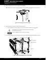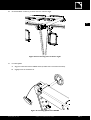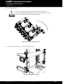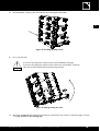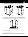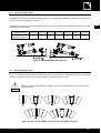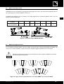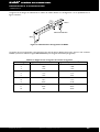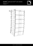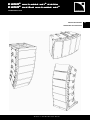
1
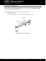
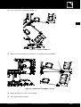
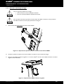
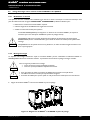
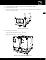
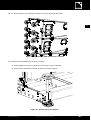
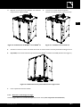
KUDO® multimulti-mode wst® system
KUDO® système multimulti-mode wst®
VERSION 2.0
2.0
www. l- aco usti cs. co m
RIGGING PROCEDURES
EN
PROCÉDURES D’ACCROCHAGE
FR
www.l-aco u sti cs.co m
1
SAFETY WARNINGS
All information hereafter detailed applies for the L-ACOUSTICS® KBUMP rigging structure or for the
L-ACOUSTICS® KLIFT or KJACKx2 rigging accessory, hereafter designated as ‘‘the product’’.
1.1
EN
Symbol description
Throughout this manual the potential risks are indicated by the following symbols:
!
The WARNING symbol indicates a potential risk of physical harm to the user or people within close
proximity to the product.
In addition, the product may also be damaged.
WARNING
!
The CAUTION symbol notifies the user about information to prevent possible product damage.
CAUTION
!
The IMPORTANT symbol is a notification of an important recommendation of use.
IMPORTANT
1.2
Important safety instructions
1. Read this manual
2. Heed all safety warnings
3. Follow all instructions
4. The user should never incorporate equipment or accessories not approved by L-ACOUSTICS®
!
WARNING
!
5. Personnel qualification
Installation and set-up should only be carried out by qualified personnel that are familiar with the
rigging techniques and safety recommendations outlined in this manual. It is recommended to attend
the training courses offered by L-ACOUSTICS® before proceeding with the installation of the
system.
6. Personnel health and safety
During installation and set-up personnel should wear protective headgear and footwear at all times.
Under no circumstances personnel should climb on the loudspeaker assembly.
WARNING
KUDO_RM_ML_2-0
www.l-aco u sti cs.co m
1 en
KUDO® multimulti-mode wst® system
RIGGING PROCEDURES
VERSION 2.0
!
WARNING
!
WARNING
!
7.
System parts and rigging inspection
All system components must be inspected before use, in order to detect any possible defects.
Please refer to the “Care and maintenance” section of this manual as well as any other manuals
pertaining to the system for a detailed description of the inspection procedure.
Any part showing any sign of defect must immediately be put aside and withdrawn from use to be
inspected by qualified service personnel.
8. Additional rigging equipment
L-ACOUSTICS® is not responsible for any rigging equipment and accessories that are not
manufactured by L-ACOUSTICS®.
It is the user’s responsibility to ensure that the Working Load Limit (WLL) of all additional hardware
rigging accessories is greater than the total weight of the loudspeaker assembly in use.
9. Suspension points
It is the user’s responsibility to ensure that the Working Load Limit (WLL) of the suspension points
and/or chain hoists is greater than the total weight of the loudspeaker assembly in use.
WARNING
!
WARNING
!
WARNING
!
WARNING
!
WARNING
10. System load capacity and setup safety limits
Load capacity and setup safety limits when flying or stacking a loudspeaker assembly should be
strictly followed according to the instructions outlined in this manual.
ALWAYS refer to the mechanical data and warning indications provided in SOUNDVISION software
(‘‘Mechanical Data’’ section) to verify the mechanical conformity of the system before installation.
11. Local regulations
Some countries require higher Ultimate Strength Safety Factors and specific rigging approvals. It is
the user’s responsibility to ensure that any overhead suspension of L-ACOUSTICS® systems has
been made in accordance with all applicable local regulations.
As a general rule, L-ACOUSTICS® recommends the use of safety steel at all times.
12. Flying a loudspeaker assembly
Always ensure that nobody is standing underneath the loudspeaker assembly when it is being raised.
As the system is being raised check each individual component to make sure that it is securely
fastened to the component above. Never leave the system unattended during the installation
process.
13. Ground stacking a loudspeaker assembly
Do not ground stack the system on uneven ground or platform.
If the system is ground stacked on a structure, platform, or stage always check that it can support the
total weight of the system.
Secure the system to the structure, platform, or stage using ratchet straps or any other applicable
devices.
WARNING
14. Dynamic load
When a loudspeaker assembly is deployed in an open air environment, wind effect should be taken
into account. Wind can produce dynamic stress to the rigging components and suspension points. If
the wind force exceeds 6 bft (Beaufort scale) it is highly recommended to lower down and/or secure
the loudspeaker assembly.
!
15. Manual
Keep this manual in a safe place during the product lifetime. This manual forms an integral part of the
product. Reselling of the product is only possible if the user manual is available. Any changes made to
the product have to be documented in writing and passed on to the buyer in the event of resale.
!
IMPORTANT
KUDO_RM_ML_2-0
www.l-aco u sti cs.co m
2 en
1.3
EC declaration of conformity
L-ACOUSTICS®
13 rue Levacher Cintrat
Parc de la Fontaine de Jouvence
91462 Marcoussis Cedex
France
EN
States that the following products:
Rigging structure, KBUMP
Rigging accessory, KLIFT
Rigging accessories, KJACKx2
Are in conformity with the provisions of:
Machinery Directive 2006/42/EC
Applied rules and standards*:
EN ISO 12100-1: 2004 (Mechanical Safety)
Established at Marcoussis, France
November 25th, 2009
Jacques Spillmann
* The general standard maximum load is as follows:
- Up to 21 KUDO® enclosures with corresponding cable set can be flown as a vertical line source array using the KBUMP rigging structure.
- Up to 6 KUDO® enclosures with corresponding cable set can be flown as a horizontal line source array using the KLIFT rigging accessory.
- Up to 6 KUDO® enclosures with corresponding cable set can be stacked as a vertical line source array using the KBUMP rigging structure
and the KJACKx2 rigging accessories.
KUDO_RM_ML_2-0
www.l-aco u sti cs.co m
3 en
KUDO® multimulti-mode wst® system
RIGGING PROCEDURES
VERSION 2.0
2
CONTENTS
1
1.1
1.2
1.3
SAFETY WARNINGS
1
Symbol description ............................................................................................................................................1
Important safety instructions..............................................................................................................................1
EC declaration of conformity .............................................................................................................................3
2
CONTENTS
3
3.1
3.2
INTRODUCTION
5
®
Welcome to L-ACOUSTICS ............................................................................................................................5
Unpacking .........................................................................................................................................................5
4
KUDO® SYSTEM
5
5.1
5.2
5.3
KUDO® RIGGING COMPONENTS
8
KBUMP rigging structure ...................................................................................................................................8
KJACKx2 rigging accessories ..............................................................................................................................9
KLIFT rigging accessory ...................................................................................................................................10
6
6.1
INSTALLATION
11
Flying a vertical line source array using KBUMP................................................................................................11
6.1.1
Modeling and safety ..........................................................................................................................11
6.1.2
Building and flying the array...............................................................................................................11
6.1.3
Taking down and disassembling the array..........................................................................................16
Ground stacking a vertical line source array using KBUMP and KJACKx2..........................................................18
6.2.1
Modeling and safety ..........................................................................................................................18
6.2.2
Building the ground stacked array .....................................................................................................18
6.2.3
Disassembling the ground stacked array............................................................................................24
Flying a horizontal line source array using KLIFT ..............................................................................................26
6.3.1
Modeling and safety ..........................................................................................................................26
6.3.2
Building and flying the array...............................................................................................................26
6.3.3
Taking down and disassembling the array..........................................................................................27
6.2
6.3
4
5
7
7.1
7.2
CARE AND MAINTENANCE
28
Maintenance information .................................................................................................................................28
Spare parts ......................................................................................................................................................28
8
SPECIFICATIONS
9
9.1
9.2
9.3
APPENDIX
30
Vertical flying options.......................................................................................................................................30
Vertical stacking options ..................................................................................................................................31
Horizontal flying options ..................................................................................................................................31
KUDO_RM_ML_2-0
29
www.l-aco u sti cs.co m
4 en
3
INTRODUCTION
3.1
Welcome to L-ACOUSTICS®
Thank you for purchasing the L-ACOUSTICS® KUDO® Multi-Mode WST® System.
EN
This manual contains essential information on the L-ACOUSTICS® KUDO® rigging procedures. Read this manual
carefully in order to become familiar with these procedures.
As part of a continuous evolution of techniques and standards, L-ACOUSTICS® reserves the right to
change the specifications of the product and the content of this manual without prior notice. Please check
the L-ACOUSTICS® web site at www.l-acoustics.com on a regular basis for latest updates.
Should the product requires repair or if information about the warranty is needed, please contact an approved
L-ACOUSTICS® distributor. The address of the nearest distributor is available on the L-ACOUSTICS® web site.
3.2
Unpacking
Carefully open the shipping carton and check the product for any noticeable damage. Each L-ACOUSTICS® product is
tested and inspected before leaving the factory and should arrive in perfect condition.
If found to be damaged, notify the shipping company or the distributor immediately. Only the consignee may initiate a
claim with the carrier for damage incurred during shipping. Be sure to save the carton and packing materials for the
carrier's inspection.
Refer to the chapter 5 for full description of the content of the KBUMP, KLIFT, and KJACKx2 shipping cartons.
4
KUDO® SYSTEM
The L-ACOUSTICS® KBUMP structure and the KLIFT and KJACK accessories are dedicated to fly and stack the
KUDO® system.
The system approach developed by L-ACOUSTICS® for KUDO® consists of the elements needed to fully take
advantage of the possible configurations and optimize the system. The main components of the system are (see also
Figure 1 and Figure 2):
KUDO®
KBUMP
KJACKx2
KLIFT
KPLA-2, KCOV
SB118, SB28
LA-RAK
LA NETWORK MANAGER
SOUNDVISION
Full range active 3-way WST® enclosure
Rigging structure to fly or stack a KUDO® array in the vertical orientation
Rigging accessories (x2) used in conjunction with the KBUMP to stack an array
Rigging accessory to fly a KUDO® array in the horizontal orientation
Removable front dolly board and protective cover to ship the KUDO®
Subwoofer enclosures for extended low frequency response
Touring rack containing three LA8 amplified controllers
Remote control software
Acoustical and mechanical modeling software
Each system configuration should first be modeled using the L-ACOUSTICS® SOUNDVISION software to verify the
mechanical conformity of the system. A detailed description on the use of the SOUNDVISION software is beyond the
scope of this manual. Please refer to the applicable documentation available on the L-ACOUSTICS® web site at www.lacoustics.com.
KUDO_RM_ML_2-0
www.l-aco u sti cs.co m
5 en
KUDO® multimulti-mode wst® system
RIGGING PROCEDURES
VERSION 2.0
KBUMP
KUDO®
KJACKx2
KLIFT
KPLA-2
KCOV
Figure 1: KUDO® system components (part 1)
KUDO_RM_ML_2-0
www.l-aco u sti cs.co m
6 en
EN
SOUNDVISION
LA NETWORK MANAGER
LA-RAK
SB118
SB28
Figure 2: KUDO® system components (part 2)
KUDO_RM_ML_2-0
www.l-aco u sti cs.co m
7 en
KUDO® multimulti-mode wst® system
RIGGING PROCEDURES
VERSION 2.0
5
KUDO® RIGGING COMPONENTS
5.1
KBUMP rigging structure
The L-ACOUSTICS® KBUMP rigging structure has been designed to fly or stack the L-ACOUSTICS® KUDO®
enclosures as a variable-curvature, vertical line source array.
Note: The stacked configurations require the use of the complimentary L-ACOUSTICS® KJACKx2 accessories (see
section 5.2).
The KBUMP package comprises the following elements (see also Figure 3):
•
One main frame.
•
Four ball locking pins, hereafter designated as ‘‘BLP’’.
•
Two shackles fitted with 22 mm/0.9 inch screw pin, hereafter designated as ‘‘22-shackles’’.
BLP
Main frame
22-shackle
Figure 3: The KBUMP rigging structure
KUDO_RM_ML_2-0
www.l-aco u sti cs.co m
8 en
5.2
KJACKx2 rigging accessories
The L-ACOUSTICS® KJACKx2 rigging accessories has been designed to attach to the KBUMP so as to form a tilted
platform to stack the L-ACOUSTICS® KUDO® enclosures as a variable-curvature, vertical line source array.
Note: The 0° tilt angle is obtained by using the KBUMP without KJACKx2.
EN
The KJACKx2 package comprises the following elements (see also Figure 4):
•
Two threaded rods.
•
Two U-brackets attached to support bases.
U-bracket
Threaded rod
Support base
KJACKx2 accessories
KJACKx2 mounted on the KBUMP
Figure 4: KJACKx2 accessories to tilt the KBUMP platform
KUDO_RM_ML_2-0
www.l-aco u sti cs.co m
9 en
KUDO® multimulti-mode wst® system
RIGGING PROCEDURES
VERSION 2.0
5.3
KLIFT rigging accessory
The L-ACOUSTICS® KLIFT rigging accessory has been designed to fly the L-ACOUSTICS® KUDO® enclosures
as a 10°-constant curvature, horizontal line source array.
The KLIFT package comprises the following elements (see also Figure 5):
•
One rigging bar.
•
One shackle fitted with 18 mm/0.7 inch screw pin, hereafter designated as ‘‘18-shackle’’.
18-shackle
Rigging bar
Figure 5: The KLIFT rigging accessory
KUDO_RM_ML_2-0
www.l-aco u sti cs.co m
10 en
6
INSTALLATION
6.1
Flying a vertical line source array using KBUMP
6.1.1
Modeling and safety
EN
Any system must be modeled before installation so as to ensure acoustical comfort and mechanical safety. This can be
done using the L-ACOUSTICS® SOUNDVISION software which will assist the user to:
• Determine the number of required KUDO® enclosures.
• Calculate the KBUMP site angle and inter-enclosure angles.
• Check the mechanical conformity of the system.
The KBUMP can fly a maximum of 21 KUDO® enclosures along with all loudspeaker cabling (refer to
the ‘‘KUDO®” user manual).
!
WARNING
6.1.2
ALWAYS refer to the mechanical data and warning indications provided in SOUNDVISION software
(‘‘Mechanical Data’’ section) to verify the mechanical conformity of the system before installation.
Building and flying the array
The KUDO® enclosure’s fully integrated rigging system allows assembling the KUDO® and KBUMP elements with no
need for any external fastening accessory. The following procedure describes how to fly a vertical KUDO® line.
!
WARNING
!
All along the procedure:
•
Strictly follow the sequence of the successive steps.
•
Ensure that each BLP is fully inserted.
•
Ensure that screw pin is correctly locked on each shackle anchor.
• For clarity purposes the loudspeaker cabling procedure will not be described.
• The loudspeaker cables will not be represented on the figures.
• Use a strain relief to avoid mechanical stress at the connector locations due to cable weight.
CAUTION
1.
Line up the KBUMP structure and all KUDO® enclosures at the rigging location.
Figure 6: Lining up the KUDO® enclosures and the KBUMP structure
KUDO_RM_ML_2-0
www.l-aco u sti cs.co m
11 en
KUDO® multimulti-mode wst® system
RIGGING PROCEDURES
VERSION 2.0
2.
On each KUDO® enclosure, adjust the K-LOUVER® panels (see the ‘‘KUDO®’’ user manual).
3.
On each KUDO® enclosure, remove the 8 BLP.
4.
On both sides of each KUDO® enclosure, push forward the rotating arm tab (accessible in the handle pocket) and
secure the front rigging point using the corresponding BLP.
Figure 7: Securing the front rigging points
5.
Align all KUDO® enclosure front rigging points (do not attach).
6.
On both sides of each KUDO® enclosure, push out the rotating arm and attach the rear inter-enclosure BLP (do
not pre-select angle).
Figure 8: Attaching the rear inter-enclosure BLP (angle selection and front rigging points are not secured)
KUDO_RM_ML_2-0
www.l-aco u sti cs.co m
12 en
7.
On both sides of the first KUDO® enclosure, select the 5° angle (the top enclosure will be parallel to the KBUMP).
EN
Figure 9: First enclosure 5° angle setting
8.
On the KBUMP structure, ensure that the 4 BLP are located in their inner storage holes.
9.
Attach the KBUMP on the top KUDO® enclosure as described below:
a.
Place the KBUMP in position by aligning both stop tabs with the top KUDO® enclosure’s front rigging points.
!
WARNING
b.
The KBUMP should be installed with the identification plate oriented towards the
rear of the array.
Support the KBUMP in order to prevent it from falling.
Attach the 4 BLP in the outer storage holes so as to secure the KBUMP to the top KUDO® enclosure.
10. Attach the 22-shackles according to the specifications detailed in appendix 9.1.
Outer storage hole
Inner storage hole
Stop tab
Figure 10: Securing the KBUMP to the first KUDO® enclosure, positioning the shackles
KUDO_RM_ML_2-0
www.l-aco u sti cs.co m
13 en
KUDO® multimulti-mode wst® system
RIGGING PROCEDURES
VERSION 2.0
11. For each KUDO® enclosure, remove both dolly board’s BLP by pulling on both lanyards.
Figure 11: Pulling on the dolly board BLP lanyards
12. Attach the motor hooks to the KBUMP shackles. Lift the KBUMP/first KUDO® assembly in the horizontal
position.
Figure 12: Raising the KBUMP/first KUDO® assembly
13. Select the desired angle between KUDO® #1 and #2 (the rotating arms slide freely between the enclosures).
Figure 13: Selecting the angle between KUDO® #1 and #2
KUDO_RM_ML_2-0
www.l-aco u sti cs.co m
14 en
14. Raise the system so as to fly the KUDO® #2.
EN
Figure 14: Flying KUDO® #2
15. Secure KUDO® #2 to KUDO® #1 by attaching both BLP to both front rigging points.
Figure 15: Securing KUDO® #2 to KUDO® #1
16. Repeat steps 13 through 15 for all KUDO® enclosures.
17. Raise the array to desired trim height.
18. Arrange / stack the dolly boards.
KUDO_RM_ML_2-0
www.l-aco u sti cs.co m
15 en
KUDO® multimulti-mode wst® system
RIGGING PROCEDURES
VERSION 2.0
6.1.3
Taking down and disassembling the array
!
All along the disassembling procedure:
• Strictly follow the sequence of the successive steps.
• Systematically ensure that each BLP is fully inserted.
WARNING
!
For clarity purposes the loudspeaker cable removing procedure will not be described.
The loudspeaker cables will not be represented on the figures.
IMPORTANT
1.
Remove both lower front BLP from the next to bottom KUDO® enclosure.
Figure 16: Detaching the next to bottom enclosure’s front rigging points
2.
Attach a dolly board on the bottom enclosure and land it on the ground by lowering the array.
3.
Remove both rear angle selection BLP on the bottom enclosure (both rear inter-enclosure BLP remain attached).
Figure 17: Removing both rear angle selection BLP
KUDO_RM_ML_2-0
www.l-aco u sti cs.co m
16 en
4.
Repeat steps 1 through 3 until the entire system is landed.
5.
Detach the motor hooks.
6.
Take down the KBUMP by removing its 4 BLP and placing them into the 4 inner storage holes.
!
EN
When removing the BLP support KBUMP in order to prevent it from falling.
WARNING
7.
For each KUDO® enclosure, remove all remaining BLP.
8.
On both sides of each KUDO® enclosure:
a.
Push the rotating arm into the captive position.
b.
Arrange the front rigging point by pushing the rigging tab inwards so that it is flush with the enclosure.
!
DO NOT push too firmly as this could indent the storage hole.
CAUTION
c.
Place both BLP in their storage locations (the rotating arm will be locked).
a.
b.
c.
Figure 18: Preparing a KUDO® enclosure for transportation
KUDO_RM_ML_2-0
www.l-aco u sti cs.co m
17 en
KUDO® multimulti-mode wst® system
RIGGING PROCEDURES
VERSION 2.0
6.2
Ground stacking a vertical line source array using KBUMP and KJACKx2
6.2.1
Modeling and safety
Any system must be modeled before installation so as to ensure acoustical comfort and mechanical safety. This can be
done using the L-ACOUSTICS® SOUNDVISION software which will assist the user to:
• Determine the number of required KUDO® enclosures.
• Calculate the KBUMP site angle and inter-enclosure angles.
• Check the mechanical conformity of the system.
The KBUMP/KJACKx2 assembly can support a maximum of 6 KUDO® enclosures (refer to appendix 9.2
for a detailed description of the vertical stacking options).
!
ALWAYS refer to the mechanical data and warning indications provided in SOUNDVISION software
(‘‘Mechanical Data’’ section) to verify the mechanical conformity of the system before installation.
WARNING
6.2.2
ALWAYS secure the KBUMP to the structure, platform, or stage using ratchet straps or any other
applicable devices.
Building the ground stacked array
The KUDO® enclosure’s fully integrated rigging system allows assembling the KUDO® and KBUMP/KJACKx2 elements
with no need for any external accessory. The following procedure describes how to stack a vertical KUDO® line.
!
All along the procedure:
•
Strictly follow the sequence of the successive steps.
•
Ensure that each BLP is fully inserted.
WARNING
!
• For clarity purposes the loudspeaker cabling procedure will not be described.
• The loudspeaker cables will not be represented on the figures.
• Use a strain relief to avoid mechanical stress at the connector locations due to cable weight.
CAUTION
1.
Line up the KUDO® enclosures and the KBUMP structure at the stacking location.
Figure 19: KUDO® and KBUMP at the stacking location
KUDO_RM_ML_2-0
www.l-aco u sti cs.co m
18 en
®
2.
On each KUDO® enclosure, adjust the K-LOUVER panels to the desired settings (see the ‘‘KUDO ®’’ user
manual).
3.
On each KUDO® enclosure, remove the 8 BLP.
4.
On both sides of each KUDO® enclosure, push forward the rotating arm tab (accessible in the handle pocket) and
secure the front rigging point using the dedicated BLP.
Figure 20: Securing the front rigging points
5.
For each rotating arm on each KUDO® enclosure:
a.
Manipulate the rotating arm to approx 10° to free the front rigging point.
b.
Align the front rigging point and attach to next KUDO® enclosure.
a.
b.
Figure 21: Securing the front rigging points to the next KUDO®
KUDO_RM_ML_2-0
www.l-aco u sti cs.co m
19 en
EN
KUDO® multimulti-mode wst® system
RIGGING PROCEDURES
VERSION 2.0
6.
Select the angle between the bottom KUDO® and the KBUMP.
Note: Selecting the 5° angle sets the bottom KUDO® site angle parallel to the KBUMP (see also appendix 9.2).
Figure 22: Selecting the first enclosure angle
7.
Attach the KBUMP to the bottom KUDO® as described below:
a.
Place the KBUMP in position by aligning the stop tabs with the bottom KUDO® front rigging points.
!
WARNING
b.
The KBUMP should be installed with the identification plate oriented
towards the rear of the array.
Support the KBUMP in order to prevent it from falling.
Attach the 4 BLP in the outer storage holes so as to secure the KBUMP to the bottom KUDO® enclosure.
Outer storage hole
Inner storage hole
Stop tab
Figure 23: Placing the KBUMP onto the first KUDO®
KUDO_RM_ML_2-0
www.l-aco u sti cs.co m
20 en
8.
On each KUDO® enclosure, pre-select the inter-enclosure angle.
EN
Figure 24: Pre-selecting inter-enclosure angles
9.
For each KJACK:
a.
Align the U-bracket with the KBUMP holes (threaded insert oriented downwards).
b.
Slightly screw the threaded rod.
Figure 25: Installing KJACK onto KBUMP
KUDO_RM_ML_2-0
www.l-aco u sti cs.co m
21 en
KUDO® multimulti-mode wst® system
RIGGING PROCEDURES
VERSION 2.0
10. Lift / rotate the stack.
!
A minimum of 2 people are required to lift a stack of 3 KUDO® enclosures.
A minimum of 3 people are required to lift a stack of 4 or more KUDO® enclosures.
Take care to avoid mechanical shock when landing the stack.
WARNING
Figure 26: Lifting / rotating the stack
11. On each KUDO® enclosure, secure both remaining rear BLP.
Figure 27: Securing the rear BLP
KUDO_RM_ML_2-0
www.l-aco u sti cs.co m
22 en
12. On each KUDO® enclosure, remove the dolly board by pulling on the captive BLP lanyards.
EN
Figure 28: Pulling on the captive BLP lanyards
13. Attach both KJACK as described below:
a.
Slightly raise the stack and place one support base in position.
b.
Use the base-supported KJACK to raise the stack and facilitate the placement of the second support base.
Figure 29: Placing the KJACK support bases in position
KUDO_RM_ML_2-0
www.l-aco u sti cs.co m
23 en
KUDO® multimulti-mode wst® system
RIGGING PROCEDURES
VERSION 2.0
14. Set the KBUMP site angle by screwing both KJACK accessories (see appendix 9.2).
Figure 30: Setting the KBUMP site angle
6.2.3
1.
Disassembling the ground stacked array
On each KUDO® enclosure, remove both lower rear BLP.
Figure 31: Removing the lower rear BLP
KUDO_RM_ML_2-0
www.l-aco u sti cs.co m
24 en
2.
On each KUDO® enclosure, place the dolly board by attaching both captive BLP.
EN
Figure 32: Installing the dolly boards
3.
Lift / rotate the stack.
!
A minimum of 3 people are required to lift a stack of 3 KUDO® enclosures.
A minimum of 5 people are required to lift a stack of 4 or more KUDO® enclosures.
Take care to avoid mechanical shock when landing the stack.
WARNING
Figure 33: Lifting/rotating the stack
4.
Take down the KBUMP and arrange the enclosures for transportation as it is shown in steps 6 through 0 in section
6.1.3 (pay attention to the warning sign).
KUDO_RM_ML_2-0
www.l-aco u sti cs.co m
25 en
KUDO® multimulti-mode wst® system
RIGGING PROCEDURES
VERSION 2.0
6.3
Flying a horizontal line source array using KLIFT
6.3.1
Modeling and safety
Any system must be modeled before installation so as to ensure acoustical comfort and mechanical safety. This can be
done using the L-ACOUSTICS® SOUNDVISION software which will assist the user to:
•
Determine the number of required KUDO® enclosures and KLIFT accessories.
•
Calculate the KLIFT site angle.
•
Check the mechanical conformity of the system.
A single KLIFT can fly a maximum of 6 KUDO® enclosures along with all loudspeaker cabling (refer to
the ‘‘KUDO®” user manual).
!
Larger horizontal arrays can be flown using several KLIFT accessories (refer to appendix 9.3).
WARNING
6.3.2
ALWAYS refer to the mechanical data and warning indications provided in SOUNDVISION software
(‘‘Mechanical Data’’ section) to verify the mechanical conformity of the system before installation.
Building and flying the array
The KUDO® enclosure’s fully integrated rigging system allows assembling the KUDO® and KLIFT elements with no
need for any external fastening accessory. The following procedure describes how to fly a horizontal 2-KUDO® line.
For larger arrays (see appendix 9.3) the procedure is similar.
!
WARNING
!
All along the procedure:
•
Strictly follow the sequence of the successive steps.
•
Ensure that each BLP is fully inserted.
•
Ensure that screw pin is correctly locked on each shackle anchor.
• For clarity purposes the loudspeaker cabling procedure will not be described.
• The loudspeaker cables will not be represented on the figures.
• Use a strain relief to avoid mechanical stress at the connector locations due to cable weight.
CAUTION
1.
On the top of a first KUDO® enclosure, slide out the
rotating arm. Select the 10° angle and secure both front and
rear rigging points using two BLP.
Figure 34: Securing both top rigging points
KUDO_RM_ML_2-0
www.l-aco u sti cs.co m
2.
Install the KLIFT accessory.
Figure 35: Installing the KLIFT
26 en
3.
Install a second KUDO® enclosure and physically secure
it to the first one using two BLP.
4.
Secure the 18-shackle to the KLIFT at the
chosen location (see appendix 9.3).
EN
Figure 36: Securing KUDO® #2 to KUDO® #1
Figure 37: Installing the 18-shackle
5.
Attach the motor hook to the 18-shackle and raise the system until it is possible to reach the array’s bottom part.
6.
If possible, slide out the lower rotating arm of the first KUDO® enclosure and attach the four lower BLP to
secure the array (with 10° angle setting).
Figure 38: Securing the array’s bottom part
7.
Raise the system to desired height.
6.3.3
Taking down and disassembling the array
Disassembling the flown horizontal array is carried out in the opposite order of how it was assembled by reversing the
order described in section 6.3.2 (pay attention to the warning instructions).
KUDO_RM_ML_2-0
www.l-aco u sti cs.co m
27 en
KUDO® multimulti-mode wst® system
RIGGING PROCEDURES
VERSION 2.0
7
CARE AND MAINTENANCE
7.1
Maintenance information
The KUDO® system assembling components are the following:
•
KBUMP rigging structure, 22-shackles, and ball locking pins.
•
KLIFT rigging accessory and 18-shackle.
•
KJACKx2 rigging accessories.
•
Rotating arms, BLP, and rigging points on each KUDO® enclosure.
If these components are used as it is described in this manual they will remain fully operational over the enclosures’ life.
However, it is necessary to regularly check the following points in order to guaranty the system durability:
!
WARNING
!
WARNING
!
The KBUMP, KLIFT, and KJACKx2 accessories as well as the shackles and BLP should not show any
deformation, fissure, or oxidation.
Any component incorporating a part showing signs of defect must immediately be replaced.
The metal components of the KUDO® enclosures should not show any signs of deformation, fissure,
or oxidation. They must be securely fixed to the enclosure.
Any enclosure incorporating a part showing signs of defect must immediately be put aside and
withdrawn from use to be inspected by qualified service personnel.
Ensure that each BLP on the KUDO® enclosures and KBUMP structure operates correctly by moving
its mechanism and checking that it automatically returns to nominal position.
WARNING
7.2
Spare parts
The spare parts available for the customer are listed in the table below. Any other part must be replaced by qualified
service personnel for safety purposes.
Table 1: Main available spare parts
MC KUDOBUMP
CA MAN22
CA KUDOPIN
CA KJACKTIGE
MC KJACKETR
CA KJACKEMB
CA KJACKVOL
CT KLIFT
CA MAN18
KUDO_RM_ML_2-0
KBUMP main frame
22-shackle
BLP
Threaded rod
U-bracket
Support base
Wheel
Rigging bar
18-shackle
www.l-aco u sti cs.co m
28 en
8
SPECIFICATIONS
Reference
KBUMP
Dimensions (L x H x D)
866 x 100 x 1000 mm / 34.1 x 3.9 x 39.4 inch
EN
Weight
44 kg / 97 lbs
Setup safety limits 1
Flown vertical array
Stacked vertical array
Maximum of 21 KUDO® enclosures per KBUMP.
Maximum of 6 KUDO® enclosures per KBUMP and KJACKx2.
Material
Polyester-coated high-grade steel.
Complementary accessories KJACKx2 supports for stacking a vertical array (available separately).
2 shackles with 22 mm/0.9 inch screw pin (included).
1
Installation safety limits are specified in the SOUNDVISION software which is designed to help with L-ACOUSTICS® product implementation.
Reference
KLIFT
Dimensions (L x H x P)
Weight
508 x 130 x 34 mm / 20 x 5.1 x 1.3 inch
2 kg / 4.4 lbs
1
Setup safety limits
Flown horizontal array
Maximum of 6 KUDO® enclosures per KLIFT
Material
Polyester-coated high-grade steel
Complementary accessory
1 shackle with 18 mm/0.7 inch screw pin
1
Installation safety limits are specified in the SOUNDVISION software which is designed to help with L-ACOUSTICS® product implementation.
KUDO_RM_ML_2-0
www.l-aco u sti cs.co m
29 en
KUDO® multimulti-mode wst® system
RIGGING PROCEDURES
VERSION 2.0
9
APPENDIX
9.1
Vertical flying options
Up to 21 KUDO® can be flown as a vertical line source array using the KBUMP rigging structure fitted with two or four
22-shackles. These last attach to the KBUMP holes as described in the following (see Figure 39 for hole numbering
convention).
Note: The KBUMP should be installed with the identification plate oriented backwards.
Side bar
Rear
Central bar
Side bar
13
Front
1
2
3
4
5
6
7
8
9 10
11
12
Identification plate
0
Figure 39: KBUMP hole numbering convention
Single-point hang can be performed off the central bar using holes from 1 to 12.
Dual-point unbridled hang can be performed off both side bars using holes from 1 to 12 (side bars spaced of
823 mm/32.4 inch) or off the central bar using holes 0 and 13 (points spaced of 900 mm/35.4 inch).
For large arrays it is recommended to use two bridled-point hangs from both side bars using holes 0 and 13 (points
spaced of 900 mm/35.4 inch).
The Ultimate Strength Safety Factor depends on the flying configuration. On the figure below, this factor is 4:1 for
single-point hang and 6:1 for the three other options.
Figure 40: KBUMP rigging options
KUDO_RM_ML_2-0
www.l-aco u sti cs.co m
30 en
9.2
Vertical stacking options
The KBUMP can be used as a horizontal stacking platform (0° tilt angle) without KJACKx2 accessories. In this case it can
support a maximum of 6 KUDO® enclosures.
The KBUMP can also be used as a tilted stacking platform with the complimentary KJACKx2 accessories. In this case
the following limitations apply:
KBUMP tilt angle
[-10°,-9°[
[-9°,-7°[
[-7°,-6°[
[-6°,-1.5°]
[1.5°,2°[
[2°,9°[
[9°,10°]
Maximum number of
KUDO® enclosures
3
4
5
6
6
5
4
Figure 41: KBUMP/KJACKx2 tilted platform
9.3
Horizontal flying options
One or more KLIFT accessories fitted with 18-shackles can fly horizontal arrays composed of a minimum of 2 KUDO®
enclosures. The Figure 42 shows six examples of single or dual suspension point arrays.
!
ONLY symmetrical configurations are available in order to equally distribute the stress values on all
suspension points.
WARNING
Figure 42: Two to seven-KUDO® horizontal arrays with KLIFT accessories
KUDO_RM_ML_2-0
www.l-aco u sti cs.co m
31 en
EN
KUDO® multimulti-mode wst® system
RIGGING PROCEDURES
VERSION 2.0
The array’s site angle will be set by securing the 18-shackle into one of the 12 pick point holes numbered in the figure
below:
9
4
1
2
5
6
10
11
12
Rear
7
3
Identification plate
Front
Figure 43: KLIFT hole numbering convention
The site angles corresponding to these pick point holes are given in the following chart for two or three KUDO®
enclosures (refer to SOUNDVISION software calculations for larger horizontal arrays):
Table 2: Pick point holes numbers and corresponding angles
Pick Point Hole Number
1
2
3
4
5
6
7
8
9
10
11
12
KUDO_RM_ML_2-0
Site angle for 2 KUDO® (1 KLIFT)
+12.8 °
+8.3 °
+3.6 °
-1 °
-5.7 °
-10.3 °
-14.8 °
-19.1 °
-23.2 °
-27 °
-30.6 °
-34 °
www.l-aco u sti cs.co m
Site angle for 3 KUDO® (2 KLIFT)
+14.3 °
+9.8 °
+5.2 °
-0.5 °
-4.2 °
-8.8 °
-13.3 °
-17.7 °
-21.8 °
-25.8 °
-29.5 °
-32.9 °
32 en
1
DÉCLARATIONS DE SÉCURITÉ
Les informations détaillées ci-dessous s’appliquent à la structure d’accrochage L-ACOUSTICS® KBUMP ou à l’un
des accessoires d’accrochage L-ACOUSTICS® KLIFT ou KJACKx2, dénommé par la suite ‘‘le produit’’.
1.1
Symboles utilisés
FR
Tout au long de ce manuel les risques potentiels sont signalés par les symboles suivants :
!
Le symbole WARNING signale un risque d’atteinte à l’intégrité physique de l’utilisateur
et de toute autre personne présente.
Le produit peut de plus être endommagé.
WARNING
!
Le symbole CAUTION signale un risque de dégradation du produit.
CAUTION
!
Le symbole IMPORTANT signale une recommandation d‘utilisation importante.
IMPORTANT
1.2
Consignes de sécurité importantes
1. Lire le présent manuel
2. Suivre les consignes de sécurité
3. Suivre les instructions
4. N’utiliser en aucun cas des équipements ou accessoires non approuvés par L-ACOUSTICS®
!
WARNING
!
5. Qualification du personnel
L’installation du système doit être effectuée par un personnel qualifié et formé aux techniques
d’accrochage et consignes de sécurité décrites dans le présent manuel.
Il est recommandé de suivre les sessions de formation L-ACOUSTICS® avant de procéder à
l’installation.
6. Santé et sécurité du personnel
Au cours de l’installation et du réglage du système toute personne présente doit porter un casque et
des chaussures de sécurité.
Dans aucune circonstance le personnel n’est autorisé à escalader un assemblage d’enceintes.
WARNING
KUDO_RM_ML_2-0
www.l-aco u sti cs.co m
1 fr
KUDO® système multimulti-mode wst®
PROCÉDURES D’ACCROCHAGE
VERSION 2.0
!
WARNING
!
WARNING
!
7. Vérification du matériel
Tous les éléments du système doivent être inspectés avant utilisation afin de détecter d’éventuels
défauts. Merci de se référer à la section ‘‘Entretien et maintenance’’ de ce manuel et des manuels
des autres éléments du système pour description des procédures d’inspection.
Tout élément présentant un défaut doit immédiatement être marqué et placé hors du circuit
d’utilisation pour inspection par un service de maintenance agréé.
8. Équipements de levage complémentaires
L-ACOUSTICS® ne peut être tenu responsable de l’utilisation d’équipements et d’accessoires de
levage fournis par d’autres fabricants.
Il est de la responsabilité de l’utilisateur de s’assurer que la Charge Maximale d’Utilisation (CMU) de
tout équipement de levage complémentaire soit supérieure au poids total du système suspendu.
9. Points de suspension
Il est de la responsabilité de l’utilisateur de s’assurer que la Charge Maximale d’Utilisation (CMU)
des points de suspension soit supérieure au poids total du système suspendu.
WARNING
!
WARNING
!
WARNING
!
WARNING
!
WARNING
!
WARNING
!
10. Limites mécaniques du système
Lors du posage ou du levage du système il est de la responsabilité de l’utilisateur de respecter les
limites mécaniques décrites dans ce manuel.
TOUJOURS se référer aux données mécaniques et aux alertes de sécurité fournies par le logiciel
SOUNDVISION (section ‘‘Mechanical Data’’) pour vérifier la conformité mécanique du système
avant montage.
11. Réglementation locale
Certains pays imposent des Coefficients de Sécurité à la Rupture supérieurs et une réglementation
spécifique pour l’installation en hauteur.
Il est de la responsabilité de l’utilisateur de s’assurer que tout levage d’un système L-ACOUSTICS®
soit réalisé dans le strict respect de la règlementation locale en vigueur.
De manière générale, L-ACOUSTICS® recommande l’utilisation d’élingues de sécurité pour toute
installation en hauteur.
12. Levage d’un système
S’assurer que personne ne se trouve au-dessous d’un système lors de son levage.
Au cours du levage du système vérifier que chaque élément soit bien accroché à l’élément
immédiatement supérieur.
Ne jamais relâcher la surveillance du système pendant la procédure d’installation.
13. Posage d’un système
Ne pas poser un système sur un sol ou plateforme instable.
Si le système est posé sur une structure, plateforme, ou scène, toujours vérifier que cette dernière
puisse supporter le poids total du système.
Arrimer le système à la structure, plateforme, ou scène à l’aide de sangles à rochet ou tout autre
moyen approprié.
14. Charge dynamique
L’influence du vent doit être prise en compte lorsqu’un système est installé en plein air. Le vent peut
engendrer des efforts dynamiques sur les éléments d’accrochage et les points de suspension. Si la
force du vent est supérieure à 6 sur l’échelle de Beaufort il est fortement recommandé de descendre
et /ou de sécuriser le système.
15. Manuel
Conserver ce manuel en lieu sûr pendant la durée de vie du produit. Ce manuel en fait partie
intégrante. La revente du produit n’est possible qu’accompagnée du présent manuel.
Toute modification du produit doit être consignée dans ce manuel en cas de revente.
IMPORTANT
KUDO_RM_ML_2-0
www.l-aco u sti cs.co m
2 fr
1.3
Déclaration de conformité CE
L-ACOUSTICS®
13 rue Levacher Cintrat
Parc de la Fontaine de Jouvence
91462 Marcoussis Cedex
France
FR
Déclare que les produits suivants :
Structure d’accrochage, KBUMP
Accessoire d’accrochage, KLIFT
Accessoires d’accrochage, KJACKx2
Sont conformes aux dispositions de :
Directive Machine 2006/42/CE
Règles et standards appliqués* :
EN ISO 12100-1 : 2004 (Sécurité Mécanique)
Fait à Marcoussis, le 25 Novembre 2009,
Jacques Spillmann
* Standard général :
- Un maximum de 21 enceintes KUDO® avec l’ensemble du câblage correspondant peut être levé en ligne verticale à l’aide de la structure
K-BUMP.
- Un maximum de 6 enceintes KUDO® avec l’ensemble du câblage correspondant peut être levé en ligne horizontale à l’aide de
l’accessoire KLIFT.
- Un maximum de 6 enceintes KUDO® avec l’ensemble du câblage correspondant peut être posé en ligne verticale à l’aide de la structure
K-BUMP et des l’accessoires KJACKx2.
KUDO_RM_ML_2-0
www.l-aco u sti cs.co m
3 fr
KUDO® système multimulti-mode wst®
PROCÉDURES D’ACCROCHAGE
VERSION 2.0
2
SOMMAIRE
1
1.1
1.2
1.3
DÉCLARATIONS DE SÉCURITÉ
1
Symboles utilisés .............................................................................................................................................1
Consignes de sécurité importantes..................................................................................................................1
Déclaration de conformité CE.........................................................................................................................3
2
SOMMAIRE
3
3.1
3.2
INTRODUCTION
5
®
Bienvenue chez L-ACOUSTICS .....................................................................................................................5
Déballage du produit.......................................................................................................................................5
4
SYSTÈME KUDO®
5
5.1
5.2
5.3
ÉLÉMENTS D’ACCROCHAGE DU KUDO®
8
Structure d’accrochage KBUMP ......................................................................................................................8
Accessoires d’accrochage KJACKx2.................................................................................................................9
Accessoire d’accrochage KLIFT.....................................................................................................................10
6
6.1
INSTALLATION
11
Levage d’une ligne source verticale à l’aide du KBUMP..................................................................................11
6.1.1 Modélisation et sécurité....................................................................................................................11
6.1.2 Montage et levage de la ligne ............................................................................................................11
6.1.3 Descente et démontage de la ligne....................................................................................................16
Posage d’une ligne source verticale à l’aide du KBUMP et des KJACKx2 ........................................................18
6.2.1 Modélisation et sécurité....................................................................................................................18
6.2.2 Montage de la ligne...........................................................................................................................18
6.2.3 Démontage de la ligne ......................................................................................................................24
Levage d’une ligne source horizontale à l’aide du KLIFT.................................................................................26
6.3.1 Modélisation et sécurité....................................................................................................................26
6.3.2 Montage et levage de la ligne ............................................................................................................26
6.3.3 Descente et démontage de la ligne....................................................................................................27
6.2
6.3
4
5
7
7.1
7.2
ENTRETIEN ET MAINTENANCE
28
Information de maintenance..........................................................................................................................28
Pièces détachées...........................................................................................................................................28
8
SPÉCIFICATIONS TECHNIQUES
9
9.1
9.2
9.3
ANNEXES
30
Options de levage vertical .............................................................................................................................30
Options de posage vertical............................................................................................................................31
Options de levage horizontal.........................................................................................................................31
KUDO_RM_ML_2-0
www.l-aco u sti cs.co m
29
4 fr
3
INTRODUCTION
3.1
Bienvenue chez L-ACOUSTICS®
Merci d’avoir fait l’acquisition du Système Multi-Mode WST® L-ACOUSTICS® KUDO®.
Ce manuel contient les informations indispensables au bon déroulement des procédures d’accrochage des systèmes
L-ACOUSTICS® KUDO®. Il est nécessaire de lire attentivement ce manuel pour se familiariser avec les procédures.
En raison de l’évolution constante des techniques et des normes, L-ACOUSTICS® se réserve le droit de
modifier sans préavis les caractéristiques des produits et les informations contenues dans ce manuel. Merci
de consulter le site internet www.l-acoustics.com pour obtenir les dernières informations de mise à jour.
Si le produit nécessite une réparation ou pour tout renseignement sur la garantie, contacter un distributeur agréé.
Les coordonnées du distributeur le plus proche sont disponibles sur le site internet L-ACOUSTICS®.
3.2
Déballage du produit
Dès réception, inspecter soigneusement le produit afin de détecter un éventuel défaut. Chaque produit
L-ACOUSTICS® est soigneusement contrôlé en sortie d’usine et doit être livré en parfait état.
À la découverte du moindre défaut, prévenir immédiatement la société de transport ou le distributeur. Seul le
destinataire peut faire réclamation pour tout dommage occasionné pendant le transport. Conservez le carton et les
pièces d’emballage pour constatation de la part de la société de livraison.
La description complète du contenu des cartons KBUMP, KLIFT, et KJACKx2 est donnée dans le chapitre 5.
4
SYSTÈME KUDO®
La structure L-ACOUSTICS® KBUMP ainsi que les accessoires KLIFT et KJACK sont dédiés au levage ou posage
du système KUDO®.
L’approche système développée par L-ACOUSTICS® pour le KUDO® comprend un ensemble d’éléments qui, associés
les uns aux autres, supporte et optimise toutes les configurations possibles. Les principaux éléments du système sont les
suivants (voir aussi les Figure 1 et Figure 2) :
KUDO®
KBUMP
KJACKx2
KLIFT
KPLA-2, KCOV
SB118, SB28
LA-RAK
LA NETWORK MANAGER
SOUNDVISION
Enceinte WST® large bande active 3 voies
Structure de levage ou posage d’une ligne source KUDO® verticale
Accessoires (x2) de posage d’une ligne source KUDO® verticale
Accessoire de levage d’une ligne source KUDO® horizontale
Plateau à roulettes et housse de protection pour le transport d’un KUDO®
Enceintes sub-graves
Rack de tournée contenant trois contrôleurs amplifiés LA8
Logiciel de pilotage à distance des contrôleurs amplifiés
Logiciel de simulation acoustique et mécanique
Chaque configuration devrait être préalablement modélisée dans l’application L-ACOUSTICS® SOUNDVISION
pour en vérifier la conformité mécanique. La description complète de l’application SOUNDVISION dépasse l’objectif du
présent manuel. Pour une information détaillée, merci de se référer à la documentation appropriée téléchargeable du
site internet www.l-acoustics.com.
KUDO_RM_ML_2-0
www.l-aco u sti cs.co m
5 fr
FR
KUDO® système multimulti-mode wst®
PROCÉDURES D’ACCROCHAGE
VERSION 2.0
KBUMP
KUDO®
KJACKx2
KLIFT
KPLA-2
KCOV
Figure 1 : Éléments du système KUDO® (partie 1)
KUDO_RM_ML_2-0
www.l-aco u sti cs.co m
6 fr
FR
SOUNDVISION
LA NETWORK MANAGER
LA-RAK
SB118
SB28
Figure 2 : Éléments du système KUDO® (partie 2)
KUDO_RM_ML_2-0
www.l-aco u sti cs.co m
7 fr
KUDO® système multimulti-mode wst®
PROCÉDURES D’ACCROCHAGE
VERSION 2.0
5
ÉLÉMENTS D’ACCROCHAGE DU KUDO®
5.1
Structure d’accrochage KBUMP
La structure d’accrochage L-ACOUSTICS® KBUMP est dédiée au levage ou posage des enceintes
L-ACOUSTICS® KUDO® en ligne source verticale à courbure variable.
Note : Les configurations posées nécessitent d’installer les accessoires complémentaires L-ACOUSTICS® KJACKx2
(voir la section 5.2).
L’ensemble KBUMP est composé des éléments suivants (voir également la Figure 3) :
•
Un cadre principal.
•
Quatre goupilles de verrouillage à bille, désignées ‘‘GVB’’ par la suite.
•
Deux manilles avec axe de diamètre 22 mm/0.9 inch, désignées ‘‘manille 22’’ par la suite.
GVB
Cadre principal
Manille 22
Figure 3 : Structure d’accrochage KBUMP
KUDO_RM_ML_2-0
www.l-aco u sti cs.co m
8 fr
5.2
Accessoires d’accrochage KJACKx2
Les accessoires d’accrochage L-ACOUSTICS® KJACKx2 s’attachent au KBUMP pour former une plateforme
inclinée dédiée au posage des enceintes L-ACOUSTICS® KUDO® en ligne source verticale à courbure variable.
Note : L’inclinaison de 0° s’obtient en utilisant la structure KBUMP sans les accessoires KJACKx2.
FR
L’ensemble KJACKx2 est composé des éléments suivants (voir également la Figure 4) :
•
Deux axes filetés.
•
Deux étriers attachés à des supports.
Étrier
Support
Axe fileté
Accessoires KJACKx2
KJACKx2 montés sur le KBUMP
Figure 4 : Accessoires KJACKx2 pour incliner la plateforme KBUMP
KUDO_RM_ML_2-0
www.l-aco u sti cs.co m
9 fr
KUDO® système multimulti-mode wst®
PROCÉDURES D’ACCROCHAGE
VERSION 2.0
5.3
Accessoire d’accrochage KLIFT
L’accessoire d’accrochage L-ACOUSTICS® KLIFT est dédié au levage des enceintes L-ACOUSTICS® KUDO® en
ligne source horizontale à courbure constante de 10°.
L’ensemble KLIFT est composé des éléments suivants (voir également la Figure 5) :
•
Une barre d’accrochage.
•
Une manille avec axe de diamètre 18 mm/0.7 inch, désignée ‘‘manille 18’’ par la suite.
Manille 18
Barre d’accrochage
Figure 5 : Accessoire d’accrochage KLIFT
KUDO_RM_ML_2-0
www.l-aco u sti cs.co m
10 fr
6
INSTALLATION
6.1
Levage d’une ligne source verticale à l’aide du KBUMP
6.1.1
Modélisation et sécurité
Tout système doit être modélisé avant installation pour assurer le confort acoustique et la sécurité mécanique. Cela
peut être effectué à l’aide du logiciel L-ACOUSTICS® SOUNDVISION qui assiste l’utilisateur pour :
• Déterminer le nombre d’enceintes KUDO® requises.
• Calculer l’angle de site du KBUMP et les angles inter-enceintes.
• Vérifier la conformité mécanique du système.
Le KBUMP peut lever un maximum de 21 enceintes KUDO® avec l’ensemble du câblage associé
(consulter le manuel d’utilisation ‘‘KUDO’’).
!
WARNING
6.1.2
TOUJOURS se référer aux données mécaniques et aux alertes de sécurité fournies par le logiciel
SOUNDVISION (section ‘‘Mechanical Data’’) pour vérifier la conformité mécanique du système avant
montage.
Montage et levage de la ligne
Le dispositif d’accrochage entièrement captif de l’enceinte KUDO® permet d’assembler les éléments KUDO® et
KBUMP sans aucun accessoire extérieur. La procédure suivante décrit le levage d’une ligne verticale KUDO®.
!
WARNING
!
Tout au long de la procédure de montage :
• Suivre strictement l’ordre des étapes successives.
• S’assurer que chaque GVB est complètement insérée.
• S’assurer que l’axe de chaque manille est fermement vissé dans son insert.
• Pour des raisons de clarté, la procédure de câblage des enceintes ne sera pas décrite.
• Les câbles d’enceintes ne seront pas représentés sur les figures.
• Accrocher les câbles pour que leur poids ne crée pas de tension mécanique sur les connecteurs.
CAUTION
1.
Aligner la structure KBUMP et toutes les enceintes KUDO® sous le point de levage.
Figure 6 : Alignement des enceintes KUDO® et de la structure KBUMP
KUDO_RM_ML_2-0
www.l-aco u sti cs.co m
11 fr
FR
KUDO® système multimulti-mode wst®
PROCÉDURES D’ACCROCHAGE
VERSION 2.0
2.
Sur chaque KUDO®, ajuster les déflecteurs K-LOUVER® (voir le manuel d’utilisation ‘‘KUDO ®’’).
3.
Sur chaque KUDO®, ôter les 8 GVB.
4.
Sur les deux côtés de chaque KUDO®, sortir le pion du bras rotatif (accessible par l’intérieur de la poignée) et
l’attacher avec la GVB correspondante.
Figure 7 : Attache des pions avant
5.
Aligner les pions de tous les KUDO® (ne pas les attacher).
6.
Sur les deux côtés de chaque KUDO®, sortir la barre angulaire du bras rotatif et l’attacher avec la GVB
correspondante (ne pas sélectionner d’angle).
Figure 8 : Attache des barres angulaires (l’angle et le pion ne sont pas attachés)
KUDO_RM_ML_2-0
www.l-aco u sti cs.co m
12 fr
7.
Sur les deux côtés du premier KUDO®, sélectionner l’angle 5° (l’enceinte sera parallèle au KBUMP).
FR
Figure 9 : Sélection de l’angle 5° sur la première enceinte
8.
Sur le KBUMP, vérifier que les 4 GVB sont enclenchées dans leurs logements internes.
9.
Fixer le KBUMP au premier KUDO® comme décrit ci-dessous :
a.
Positionner le KBUMP en posant ses deux équerres d’arrêt sur les deux pions du premier KUDO®.
Le KBUMP doit être installé avec la platine d’identification orientée vers l’arrière de
la ligne source.
!
WARNING
Soutenir le KBUMP pour éviter sa chute.
b. Attacher les 4 GVB dans leurs logements externes de façon à fixer le KBUMP au premier KUDO®.
10. Attacher les manilles 22 selon les spécifications fournies en annexe 9.1.
Logement externe
Logement interne
Équerre d’arrêt
Figure 10 : Fixation du KBUMP au premier KUDO® et attache des manilles
KUDO_RM_ML_2-0
www.l-aco u sti cs.co m
13 fr
KUDO® système multimulti-mode wst®
PROCÉDURES D’ACCROCHAGE
VERSION 2.0
11. Sur chaque KUDO®, ôter les 2 GVB du plateau à roulettes en tirant sur leurs élingues.
Figure 11 : Séparation des GVB du plateau à roulettes
12. Attacher les crochets des moteurs aux manilles du KBUMP. Lever l’assemblage KBUMP/premier KUDO® en
position horizontale.
Figure 12 : Levage de l’ensemble KBUMP/premier KUDO®
13. Sélectionner l’angle désiré entre les KUDO® n°1 et n°2 (les bras rotatifs translatent librement entre les enceintes).
Figure 13 : Sélection de l’angle entre les KUDO® n°1 et n°2
KUDO_RM_ML_2-0
www.l-aco u sti cs.co m
14 fr
14. Lever le système pour suspendre le KUDO® n°2.
FR
Figure 14 : Levage du KUDO® n°2
15. Solidariser l’avant du KUDO® n°2 au KUDO® n°1 en utilisant les deux GVB dédiées.
Figure 15 : Solidarisation des KUDO® n°2 et n°1
16. Répéter les étapes 13 à 15 pour tous les KUDO®.
17. Lever la ligne à la hauteur désirée.
KUDO_RM_ML_2-0
www.l-aco u sti cs.co m
15 fr
KUDO® système multimulti-mode wst®
PROCÉDURES D’ACCROCHAGE
VERSION 2.0
6.1.3
Descente et démontage de la ligne
!
Tout au long de la procédure de montage :
• Suivre strictement l’ordre des étapes successives.
• S’assurer que chaque GVB est complètement insérée.
WARNING
!
Pour des raisons de clarté, la procédure de déconnexion des câbles d’enceintes ne sera pas décrite.
Les câbles d’enceintes ne seront pas représentés sur les figures.
IMPORTANT
1.
Ôter les deux GVB avant basses de l’avant-dernier KUDO®.
Figure 16 : Séparation des points de fixation avant de l’avant-dernier KUDO®
2.
Attacher un plateau à roulettes sur le dernier KUDO® et le poser au sol en descendant la ligne.
3.
Ôter les deux GVB de sélection angulaire sur le dernier KUDO® (les deux autres GVB de fixation de la barre
angulaire restent attachées).
Figure 17 : Séparation des GVB de sélection angulaire
KUDO_RM_ML_2-0
www.l-aco u sti cs.co m
16 fr
4.
Répéter les étapes 1 à 3 jusqu’à ce que la totalité du système soit posée au sol.
5.
Détacher les crochets des moteurs.
6.
Déposer le KBUMP en ôtant ses 4 GVB et en les replaçant dans leurs logements internes.
!
Au moment d’ôter les GVB, soutenir le KBUMP pour éviter sa chute.
FR
WARNING
7.
Sur chaque KUDO®, ôter toutes les GVB encore enclenchées.
8.
Sur les deux côtés de chaque KUDO® :
a. Rentrer la barre angulaire du bras rotatif.
b. Rentrer le pion du bras rotatif.
!
NE PAS rentrer le pion trop fermement car cela risquerait de déformer le logement
de stockage.
CAUTION
c. Attacher les 2 GVB dans leurs logements (le bras rotatif est bloqué en position rentrée).
a.
b.
c.
Figure 18 : Configuration du KUDO® pour le transport
KUDO_RM_ML_2-0
www.l-aco u sti cs.co m
17 fr
KUDO® système multimulti-mode wst®
PROCÉDURES D’ACCROCHAGE
VERSION 2.0
6.2
Posage d’une ligne source verticale à l’aide du KBUMP et des KJACKx2
6.2.1
Modélisation et sécurité
Tout système doit être modélisé avant installation pour assurer le confort acoustique et la sécurité mécanique. Cela
peut être effectué à l’aide du logiciel L-ACOUSTICS® SOUNDVISION qui assiste l’utilisateur pour :
• Déterminer le nombre d’enceintes KUDO® requises.
• Calculer l’angle de site du KBUMP et les angles inter-enceintes.
• Vérifier la conformité mécanique du système.
L’ensemble KBUMP/KJACKx2 peut supporter un maximum de 6 enceintes KUDO® (se reporter à
l’annexe 9.2 pour une description détaillée des options de posage vertical).
TOUJOURS se référer aux données mécaniques et aux alertes de sécurité fournies par le logiciel
SOUNDVISION (section ‘‘Mechanical Data’’) pour vérifier la conformité mécanique du système avant
montage.
!
WARNING
6.2.2
TOUJOURS arrimer le système à la structure, plateforme, ou scène à l’aide de sangles à rochet ou tout
autre moyen approprié.
Montage de la ligne
Le dispositif d’accrochage entièrement captif de l’enceinte KUDO® permet d’assembler les éléments KUDO® et
KBUMP/KJACKx2 sans aucun accessoire extérieur. La procédure suivante décrit le posage d’une ligne verticale.
!
Tout au long de la procédure de montage :
• Suivre strictement l’ordre des étapes successives.
• S’assurer que chaque GVB est complètement insérée.
WARNING
!
• Pour des raisons de clarté, la procédure de câblage des enceintes ne sera pas décrite.
• Les câbles d’enceintes ne seront pas représentés sur les figures.
• Accrocher les câbles pour que leur poids ne crée pas de tension mécanique sur les connecteurs.
CAUTION
1. Aligner les enceintes KUDO® et la structure KBUMP au point de posage.
Figure 19 : Alignement des KUDO® et du KBUMP au point de posage
KUDO_RM_ML_2-0
www.l-aco u sti cs.co m
18 fr
®
2. Sur chaque KUDO®, ajuster les déflecteurs K-LOUVER (voir le manuel d’utilisation ‘‘KUDO ®’’).
3. Sur chaque KUDO®, ôter les 8 GVB.
4.
Sur les deux côtés de chaque KUDO®, sortir le pion du bras rotatif (accessible par l’intérieur de la poignée) et
l’attacher avec la GVB correspondante.
FR
Figure 20 : Attache des pions
5. Sur les deux côtés de chaque KUDO® :
a. Sortir la barre angulaire à la graduation 10° pour libérer le pion.
b. Aligner les pions et les attacher au KUDO® suivant.
a.
b.
Figure 21 : Attache des pions sur le KUDO® suivant
KUDO_RM_ML_2-0
www.l-aco u sti cs.co m
19 fr
KUDO® système multimulti-mode wst®
PROCÉDURES D’ACCROCHAGE
VERSION 2.0
6. Sélectionner l’angle entre le premier KUDO® et le KBUMP.
Note : L’angle 5° positionne le premier KUDO® parallèlement au KBUMP (voir aussi l’annexe 9.2).
Figure 22 : Sélection de l’angle du premier KUDO®
7. Attacher le KBUMP au premier KUDO® comme décrit ci-dessous :
a.
Positionner le KBUMP en posant ses deux équerres d’arrêt sur les deux pions du premier KUDO®.
!
WARNING
b.
Le KBUMP doit être installé avec la platine d’identification orientée vers
l’arrière de la ligne.
Soutenir le KBUMP pour éviter sa chute.
Attacher les 4 GVB dans leurs logements externes de façon à fixer le KBUMP au premier KUDO®.
Logement externe
Logement interne
Équerre d’arrêt
Figure 23 : Positionnement du KBUMP sur le premier KUDO®
KUDO_RM_ML_2-0
www.l-aco u sti cs.co m
20 fr
8. Sur chaque KUDO®, présélectionner l’angle.
FR
Figure 24 : Présélection de l’angle
9. Pour chaque KJACK :
a.
Aligner l’étrier avec les perçages du KBUMP (l’insert fileté orienté à l’opposé des enceintes).
b.
Visser l’axe fileté.
Figure 25 : Installation du KJACK sur le KBUMP
KUDO_RM_ML_2-0
www.l-aco u sti cs.co m
21 fr
KUDO® système multimulti-mode wst®
PROCÉDURES D’ACCROCHAGE
VERSION 2.0
10. Faire pivoter le système en position verticale.
!
WARNING
Faire pivoter un système de 3 KUDO® nécessite l’intervention de 2 personnes au minimum.
Faire pivoter un système de 4 KUDO® ou plus nécessite l’intervention de 3 personnes au
minimum.
Éviter les chocs mécaniques pendant l’opération.
Figure 26 : Positionnement du système en ligne verticale
11. Sur chaque KUDO®, attacher les 2 GVB non encore enclenchées.
Figure 27 : Attache des GVB arrière
KUDO_RM_ML_2-0
www.l-aco u sti cs.co m
22 fr
12. Sur chaque KUDO®, ôter le plateau à roulettes en tirant sur les élingues des 2 GVB.
FR
Figure 28 : Séparation des GVB des plateaux à roulettes
13. Attacher les deux KJACKx2 comme décrit ci-dessous :
a. Soulever légèrement le système et placer l’un des supports sous son axe fileté.
b. Visser ce même axe fileté pour faciliter le placement du second support.
Figure 29 : Positionnement des supports
KUDO_RM_ML_2-0
www.l-aco u sti cs.co m
23 fr
KUDO® système multimulti-mode wst®
PROCÉDURES D’ACCROCHAGE
VERSION 2.0
14. Régler l’angle de site du KBUMP en vissant les deux accessoires KJACKx2 (voir l’annexe 9.2).
Figure 30 : Réglage de l’angle de site du KBUMP
6.2.3
Démontage de la ligne
1. Sur chaque KUDO®, ôter les 2 GVB arrières basses.
Figure 31 : Séparation des GVB arrières inférieures
KUDO_RM_ML_2-0
www.l-aco u sti cs.co m
24 fr
2. Sur chaque KUDO®, installer le plateau à roulettes en attachant les 2 GVB correspondantes.
FR
Figure 32 : Installation des plateaux à roulettes
3. Faire pivoter le système en position horizontale.
!
WARNING
Faire pivoter un système de 3 KUDO® nécessite l’intervention de 3 personnes au minimum.
Faire pivoter un système de 4 KUDO® ou plus nécessite l’intervention de 5 personnes au
minimum.
Éviter les chocs mécaniques pendant l’opération.
Figure 33 : Positionnement horizontal du système
4. Déposer le KBUMP et configurer les KUDO® pour le transport, comme cela est décrit dans les étapes 6 à 8 de la
section 6.1.3 (en tenant compte de l’avertissement).
KUDO_RM_ML_2-0
www.l-aco u sti cs.co m
25 fr
KUDO® système multimulti-mode wst®
PROCÉDURES D’ACCROCHAGE
VERSION 2.0
6.3
Levage d’une ligne source horizontale à l’aide du KLIFT
6.3.1
Modélisation et sécurité
Tout système doit être modélisé avant installation pour assurer le confort acoustique et la sécurité mécanique. Cela
peut être effectué à l’aide du logiciel L-ACOUSTICS® SOUNDVISION qui assiste l’utilisateur pour :
•
Déterminer le nombre d’enceintes KUDO® et d’accessoires KLIFT requis.
•
Calculer l’angle de site des KLIFT.
•
Vérifier la conformité mécanique du système.
Un unique KLIFT peut lever un maximum de 6 enceintes KUDO® avec l’ensemble du câblage associé
(consulter le manuel d’utilisation ‘‘KUDO’’).
Des lignes horizontales plus grandes peuvent être levées à l’aide de plusieurs accessoires K-LIFT
(consulter l’annexe 9.3).
!
WARNING
6.3.2
TOUJOURS se référer aux données mécaniques et aux alertes de sécurité fournies par le logiciel
SOUNDVISION (section ‘‘Mechanical Data’’) pour vérifier la conformité mécanique du système avant
montage.
Montage et levage de la ligne
Le dispositif d’accrochage entièrement captif de l’enceinte KUDO® permet d’assembler les éléments KUDO® et KLIFT
sans aucun accessoire extérieur. La procédure suivante décrit le levage d’une ligne horizontale de 2 KUDO®. Pour des
lignes plus importantes (voir l’annexe 9.3) la procédure est similaire.
!
WARNING
Tout au long de la procédure de montage :
• Suivre strictement l’ordre des étapes successives.
• S’assurer que chaque GVB est complètement insérée.
• S’assurer que l’axe de chaque manille est fermement vissé dans son insert.
• Pour des raisons de clarté, la procédure de câblage des enceintes ne sera pas décrite.
• Les câbles d’enceintes ne seront pas représentés sur les figures.
• Accrocher les câbles pour que leur poids ne crée pas de tension mécanique sur les connecteurs.
!
CAUTION
1.
Sur la face supérieure d’une première enceinte KUDO®,
sortir le bras rotatif. Sélectionner l’angle 10° et attacher les 2
GVB avant et arrière.
Figure 34 : Sécurisation du bras supérieur
KUDO_RM_ML_2-0
www.l-aco u sti cs.co m
2.
Installer l’accessoire KLIFT.
Figure 35 : Installation du KLIFT
26 fr
3.
Disposer une seconde enceinte KUDO® et la solidariser
à la première en utilisant 2 GVB.
4.
Accrocher la manille 18 dans le logement
adéquat de l’accessoire KLIFT (voir l’annexe 9.3).
FR
Figure 36 : Solidarisation du KUDO® n°2 au KUDO® n°1
Figure 37 : Installation de la manille 18
5.
Attacher le crochet du moteur à la manille 18 et lever de manière à avoir accès à la partie basse de la ligne source.
6.
Si possible, sortir le bras rotatif de la première enceinte KUDO® et attacher les 4 GVB (sélectionner l’angle 10°).
Figure 38 : Solidarisation de la partie inférieure de la ligne source
7.
Lever le système à la hauteur désirée.
6.3.3
Descente et démontage de la ligne
Le démontage s’effectue en inversant les étapes de la section 6.3.2 (tenir compte des avertissements).
KUDO_RM_ML_2-0
www.l-aco u sti cs.co m
27 fr
KUDO® système multimulti-mode wst®
PROCÉDURES D’ACCROCHAGE
VERSION 2.0
7
ENTRETIEN ET MAINTENANCE
7.1
Information de maintenance
Le dispositif d’accrochage du système KUDO® est constitué des éléments suivants :
•
Structure d’accrochage KBUMP, manilles 22, et goupilles de verrouillage à billes.
•
Accessoire d’accrochage KLIFT et manilles 18.
•
Accessoires d’accrochage KJACKx2.
•
Bras rotatifs, GVB, et points d’accrochage sur chaque enceinte KUDO®.
S’ils sont utilisés dans le strict respect des procédures décrites dans ce manuel, ces éléments doivent rester
opérationnels pendant la durée de vie des enceintes. Cependant, dans le but de garantir leur durabilité, vérifier
régulièrement les points suivants :
!
WARNING
!
WARNING
!
Les accessoires KBUMP, KLIFT, et KJACKx2 ainsi que les manilles et GVB ne doivent pas présenter de
déformation, fissure, ou corrosion.
Tout élément présentant un défaut doit immédiatement être remplacé.
Les parties métalliques des enceintes KUDO® ne doivent pas présenter de déformation, fissure, ou
corrosion. Elles doivent être fermement fixées aux enceintes.
Toute enceinte présentant un défaut doit immédiatement être marquée et placée hors du circuit
d’utilisation pour inspection par un service de maintenance agréé.
Vérifier le bon fonctionnement des GVB sur les enceintes KUDO® et la structure KBUMP : actionner le
mécanisme de rétractation et s’assurer qu’il reprend automatiquement sa position d’origine.
WARNING
7.2
Pièces détachées
Les pièces détachées disponibles pour l’utilisateur sont listées ci-dessous. Toute autre pièce doit être remplacée par un
service de maintenance agréé pour des raisons de sécurité.
Tableau 1 : Pièces détachées disponibles pour l’utilisateur
MC KUDOBUMP
CA MAN22
CA KUDOPIN
CA KJACKTIGE
MC KJACKETR
CA KJACKEMB
CA KJACKVOL
CT KLIFT
CA MAN18
KUDO_RM_ML_2-0
Cadre principal du KBUMP
Manille 22
GVB
Axe fileté
Étrier
Support
Volant
Barre d’accrochage
Manille 18
www.l-aco u sti cs.co m
28 fr
8
SPÉCIFICATIONS TECHNIQUES
Référence
KBUMP
Dimensions (L x H x P)
866 x 100 x 1000 mm / 34.1 x 3.9 x 39.4 inch
FR
Poids
44 kg / 97 lbs
Limites de sécurité 1
Ligne verticale levée
Ligne verticale posée
Maximum de 21 enceintes KUDO® par KBUMP.
Maximum de 6 enceintes KUDO® par KBUMP et KJACKx2.
Matériau
Acier haute résistance avec revêtement polyester.
Accessoires complémentaires
Supports KJACKx2 pour poser une ligne verticale (disponibles séparément).
2 manilles avec axe de 22 mm/0.9 inch (inclus).
1
Les limites d’utilisation sont indiquées dans SOUNDVISION, logiciel d’aide à l’exploitation des produits L-ACOUSTICS®.
Référence
KLIFT
Dimensions (L x H x P)
508 x 130 x 34 mm / 20 x 5.1 x 1.3 inch
Poids
2 kg / 4.4 lbs
1
Limites de sécurité
Ligne horizontale levée
Maximum de 6 enceintes KUDO® par KLIFT
Matériau
Acier haute résistance avec revêtement polyester
Accessoire complémentaire
1 manille avec axe de 18 mm/0.7 inch (inclus)
1
Les limites d’utilisation sont indiquées dans SOUNDVISION, logiciel d’aide à l’exploitation des produits L-ACOUSTICS®.
KUDO_RM_ML_2-0
www.l-aco u sti cs.co m
29 fr
KUDO® système multimulti-mode wst®
PROCÉDURES D’ACCROCHAGE
VERSION 2.0
9
ANNEXES
9.1
Options de levage vertical
Il est possible de lever jusqu’à 21 enceintes KUDO® à l’aide de la structure d’accrochage KBUMP munie de 2 ou 4
manilles 22. Ces dernières s’attachent aux logements du KBUMP comme décrit par la suite (la numérotation des
logements des manilles est donnée en Figure 39).
Note : Le KBUMP doit être installé avec la platine d’identification orientée vers l’arrière de la ligne source.
Barre latérale
Arrière
Barre centrale
Barre latérale
13
Avant
1
2
3
4
5
6
7
8
9 10
11
12
Platine d’identification
0
Figure 39 : Numérotation des logements de manilles sur le KBUMP
Pour une suspension à un point on utilise les logements 1 à 12 de la barre centrale.
Pour une suspension à deux points non bridés on peut utiliser les logements 1 à 12 des barres latérales (espacées de
823 mm/32.4 inch) ou les logements 0 et 13 de la barre centrale (espacés de 900 mm/35.4 inch).
Pour des lignes sources de grandes dimensions il est recommandé d’utiliser deux brides à deux points accrochées aux
logements 0 et 13 des barres latérales (espacés de 900 mm/35.4 inch).
Le Coefficient de Sécurité à la Rupture dépend de la configuration d’accrochage. Dans la figure ci-dessous, ce coefficient
est 4 :1 pour un point d’accrochage et 6:1 pour les trois autres configurations.
Figure 40 : Configurations d’accrochage du KBUMP
KUDO_RM_ML_2-0
www.l-aco u sti cs.co m
30 fr
9.2
Options de posage vertical
Le KBUMP peut servir de plateforme de posage horizontale (angle de site de 0°) sans les accessoires KJACKx2. Dans ce
cas, il peut supporter 6 enceintes KUDO® au maximum.
Le KBUMP peut également servir de plateforme de posage anglée avec les accessoires KJACKx2. Dans ce cas, les
limitations suivantes s’appliquent :
Angle de site du
K-BUMP
Nombre maximum
d’enceintes KUDO®
[-10°,-9°[
[-9°,-7°[
[-7°,-6°[
[-6°,-1.5°]
[1.5°,2°[
[2°,9°[
[9°,10°]
3
4
5
6
6
5
4
Figure 41 : Plateforme anglée KBUMP/KJACKx2
9.3
Options de levage horizontal
Un ou plusieurs accessoires KLIFT munis de manilles 18 peuvent lever des lignes horizontales composées d’un
minimum de 2 enceintes KUDO®. La Figure 42 montre 6 exemples de lignes suspendues à un ou deux points.
!
SEULES les configurations symétriques sont autorisées de manière à répartir équitablement les efforts
entre tous les points de suspension.
WARNING
Figure 42 : Lignes sources horizontales de 2 à 7 enceintes KUDO® avec accessoires KLIFT
KUDO_RM_ML_2-0
www.l-aco u sti cs.co m
31 fr
FR
KUDO® système multimulti-mode wst®
PROCÉDURES D’ACCROCHAGE
VERSION 2.0
L’angle de site de la ligne est sélectionné en insérant la manille 18 dans l’un des logements 1 à 12 représentés sur la
figure ci-dessous :
9
4
1
2
5
6
10
11
12
Arrière
7
3
Platine d’identification
Avant
Figure 43 : Numérotation des logements du KLIFT
Les angles de site correspondant à ces logements sont donnés dans le tableau suivant pour deux ou trois enceintes
KUDO® (merci de se référer au logiciel SOUNDVISION pour les lignes horizontales plus grandes) :
Tableau 2 : Angles de site en fonction du numéro de logement
Numéro de logement
1
2
3
4
5
6
7
8
9
10
11
12
KUDO_RM_ML_2-0
Angle de site pour 2 KUDO® (1 KLIFT)
+12.8 °
+8.3 °
+3.6 °
-1 °
-5.7 °
-10.3 °
-14.8 °
-19.1 °
-23.2 °
-27 °
-30.6 °
-34 °
Angle de site pour 3 KUDO® (2 KLIFT)
+14.3 °
+9.8 °
+5.2 °
-0.5 °
-4.2 °
-8.8 °
-13.3 °
-17.7 °
-21.8 °
-25.8 °
-29.5 °
-32.9 °
www.l-aco u sti cs.co m
32 fr
www.l-aco u sti cs.co m
Document reference: KUDO_RM_ML_2-0
_________________
© 2009 L-ACOUSTICS®. All rights reserved.
No part of this publication may be reproduced or transmitted in any form
or by any means without the express written consent of the publisher.
_________________
Printed on recycled paper
Distribution date: November 27th, 2009
www.l-aco u sti cs.co m