1
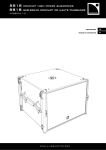
SB18
compact high power subwoofer
USER MANUAL
VERSION 1.0
1.0
www. l- aco usti cs. co m
www.l-aco u sti cs.co m
1 SAFETY WARNINGS
All information hereafter detailed applies for the L-ACOUSTICS® SB18 Compact High Power Subwoofer,
designated in this section as ‘‘the product’’.
1.1
Symbol description
EN
Throughout this manual the potential risks are indicated by the following symbols:
WARNING
The WARNING symbol indicates a potential risk of physical harm to the user or people within close
proximity to the product.
In addition, the product may also be damaged.
The CAUTION symbol notifies the user about information to prevent possible product damage.
CAUTION
The IMPORTANT symbol is a notification of an important recommendation of use.
IMPORTANT
1.2
Important safety instructions
1.
Read this manual
2.
Heed all safety warnings
3.
Follow all instructions
4.
The user should never incorporate equipment or accessories not approved by L-ACOUSTICS®
WARNING
5. Sound Levels
Sound systems are capable of producing high Sound Pressure Levels which can be dangerous and potentially
cause hearing damage especially when exposed to them over a long period of time.
Do not stay within close proximity of the loudspeakers when operating.
6. Heat
Do not operate the product near any heat source, such as radiators or other devices.
CAUTION
CAUTION
WARNING
7. Water and moisture
Even if the product is weather-resistant, it can not be exposed to moisture (rain, sea spray, shower, steam)
for a long period of time, nor put in direct contact or partially immersed in water. This would cause
irreversible damage to exposed components.
8. System parts and rigging inspection
All system components must be inspected before use, in order to detect any possible defects.
Please refer to the Care and Maintenance section of this manual as well as any other manuals pertaining
to the system for a detailed description of the inspection procedure.
Any part showing any sign of defect must immediately be put aside and withdrawn from use to be inspected
by qualified service personnel.
SB18_UM_ML_1-0
www.l-aco u sti cs.co m
1 en
SB18
SB18 COMPACT HIGH POWER SUBWOOFER
USER MANUAL
VERSION 1.0
WARNING
9. Mounting instructions
Do not place the product on an unstable cart, stand, tripod, bracket, or table. The product may fall and be
seriously damaged, and may cause serious human injury. Any mounting of the product should follow the
manufacturer’s instructions given in this manual, and should use a mounting accessory recommended by the
manufacturer.
10. Conditions which require immediate service
Servicing is required when the product has been damaged in any way such as:
• The product has been exposed to rain or moisture.
• The product was dropped or the enclosure is damaged.
CAUTION
• The product does not operate normally.
IMPORTANT
1.3
11. Manual
Keep this manual in a safe place during the product lifetime. This manual forms an integral part of the
product. Reselling of the product is only possible if the user manual is available. Any changes made to the
product have to be documented in writing and passed on to the buyer in the event of resale.
EC declaration of conformity
L-ACOUSTICS®
13 rue Levacher Cintrat
Parc de la Fontaine de Jouvence
91462 Marcoussis Cedex
France
States that the following product:
Loudspeaker enclosure, SB18
Is in conformity with the provisions of:
Low Voltage Directive 2006/95/EC
Applied rules and standards:
EN60065 (Electrical Safety)
Established at Marcoussis, France
March 1st, 2010
Christophe Pignon
Head of Research & Development dept.
SB18_UM_ML_1-0
www.l-aco u sti cs.co m
2 en
2 CONTENTS
1
1.1
1.2
1.3
SAFETY WARNINGS
1
Symbol description ............................................................................................................................................1
Important safety instructions..............................................................................................................................1
EC declaration of conformity .............................................................................................................................2
2
CONTENTS
3
3.1
3.2
3.3
3.4
INTRODUCTION
4
®
Welcome to L-ACOUSTICS ............................................................................................................................4
Symbol description ............................................................................................................................................4
Unpacking .........................................................................................................................................................4
Web links ..........................................................................................................................................................4
4
SYSTEM APPROACH
5
5
SB18 SUBWOOFER
8
6
6.1
6.2
6.3
INSTALLATION
9
SB18 transport ..................................................................................................................................................9
SB18 flying or stacking .......................................................................................................................................9
SB18 connection................................................................................................................................................9
7
7.1
7.2
OPERATION
12
System configuration........................................................................................................................................12
STANDARD mode ..........................................................................................................................................12
7.2.1
Description.......................................................................................................................................12
7.2.2
Connecting the SB18 to the LA4 or LA8 ...........................................................................................13
7.2.3
[SB18_60] and [SB18_100] presets ...................................................................................................14
CARDIOID mode............................................................................................................................................15
7.3.1
Description.......................................................................................................................................15
7.3.2
Connecting the SB18 to the LA4 or LA8 ...........................................................................................16
7.3.3
[SB18_60_C] and [SB18_100_C] presets ..........................................................................................17
EN
7.3
8
8.1
8.2
3
8.3
CARE AND MAINTENANCE
18
Maintenance information .................................................................................................................................18
Testing procedure ...........................................................................................................................................18
8.2.1
Acoustical check ...............................................................................................................................18
8.2.2
Mechanical check..............................................................................................................................18
8.2.3
External aspect .................................................................................................................................18
Authorized service procedures ........................................................................................................................19
8.3.1
Replacement kits and recommended tools ........................................................................................19
8.3.2
Front face.........................................................................................................................................20
8.3.3
Protective edges and handles ............................................................................................................20
8.3.4
Pole mount socket............................................................................................................................20
8.3.5
Transducer .......................................................................................................................................21
8.3.6
Connector plate ...............................................................................................................................21
9
SPECIFICATIONS
SB18_UM_ML_1-0
22
www.l-aco u sti cs.co m
3 en
SB18
SB18 COMPACT HIGH POWER SUBWOOFER
USER MANUAL
VERSION 1.0
3 INTRODUCTION
3.1
Welcome to L-ACOUSTICS®
Thank you for purchasing the L-ACOUSTICS® SB18 Compact High Power Subwoofer.
This manual contains essential information on installing and operating the product correctly and safely. Read this manual
carefully in order to become familiar with these procedures.
As part of a continuous evolution of techniques and standards, L-ACOUSTICS® reserves the right to
change the specifications of the product and the content of this manual without prior notice.
Should the product requires repair or if information about the warranty is needed, please contact an approved
L-ACOUSTICS® distributor. The address of the nearest distributor is available on the L-ACOUSTICS® web site.
3.2
Symbol description
All along the manual, a bracketed number refers to a section. For example, [3.2] stands for the present Symbol
description section.
3.3
Unpacking
Carefully open the shipping carton and check the product for any noticeable damage. Each L-ACOUSTICS® product is
tested and inspected before leaving the factory and should arrive in perfect condition.
If found to be damaged, notify the shipping company or the distributor immediately. Only the consignee may initiate a
claim with the carrier for damage incurred during shipping. Be sure to save the carton and packing materials for the
carrier's inspection.
3.4
Web links
Please check the L-ACOUSTICS® web site on a regular basis for latest document and software application updates.
Table 1 provides links for all downloadable items mentioned in this manual.
ALWAYS refer to the latest document version.
ALWAYS use the latest software application version.
IMPORTANT
Table 1: Links to documents and software applications
Generic path for all products
SB18 User manual
SB18 Rigging manual
KARA User manual
KARA Rigging manual
LA4 User manual
LA8 User manual
LA4 PRESET LIBRARY
LA8 PRESET LIBRARY
LA NETWORK MANAGER User manual
SOUNDVISION Software
LA8 CACOM CABLES Technical bulletin
SB18_UM_ML_1-0
www.l-acoustics.com/+product name
www.l-acoustics.com/sb18 (USER MANUAL)
www.l-acoustics.com/sb18 (RIGGING MANUAL)
www.l-acoustics.com/kara (USER MANUAL)
www.l-acoustics.com/kara (RIGGING MANUAL)
www.l-acoustics.com/la4 (USER MANUAL)
www.l-acoustics.com/la8 (USER MANUAL)
www.l-acoustics.com/la4 (LA4 PRESET LIBRARY)
www.l-acoustics.com/la8 (LA8 PRESET LIBRARY)
www.l-acoustics.com/la-network-manager (USER MANUAL)
www.l-acoustics.com/soundvision
www.l-acoustics.com/download (Technical publications)
www.l-aco u sti cs.co m
4 en
4 SYSTEM APPROACH
The L-ACOUSTICS® SB18 is the universal subwoofer designed for modular or fixed angle WST® line sources
(KUDO®, KIVA/KILO, KARA®, ARCS®) and coaxial systems (XT), lowering the combined system operating range down
to 32 Hz. Its compact size and integrated rigging make it extremely well suited for flown coupled configurations with
KARA® (refer to the KARA Rigging manual [3.4]).
EN
The system approach developed by L-ACOUSTICS® for SB18 consists of the elements needed to fully optimize the
possible configurations. The main components of the system are (see also Figure 1 and Figure 2):
SB18
M-BUMP
M-BAR
M-JACK
SB18PLA
SB18COV
8XT, 12XT, 115XT HiQ
KIVA, ARCS®, KARA®
KUDO®
KILO
LA4, LA8
LA-RAK
LA NETWORK MANAGER
SOUNDVISION
Compact high power subwoofer
Structure for flying or stacking a vertical KARA and/or SB18 array
Extension bar for M-BUMP
Stacking bases (x4) for vertical KARA and/or SB18 arrays
Removable front dolly board for SB18
Protective cover for SB18
XT coaxial range enclosures
2-way WST® systems
3-way WST® system
LF extension for KIVA
Amplified controllers
Touring rack containing three LA8 amplified controllers
Remote control software
Acoustical and mechanical modeling software
The SB18 subwoofer is compatible with standard L-ACOUSTICS® accessories. These accessories include the
L-ACOUSTICS® SP.7, SP10, and SP25 Loudspeaker cables with respective lengths of 0.7 m/2.3 ft, 10 m/32.8 ft,
and 25 m/82 ft. These cables allow connection of the SB18 enclosure to the LA4 amplified controller. Each cable is a 4conductor cable with 4 mm2 conductor cross-section (13 SWG, 11 AWG) and features 4-point SpeakON® connectors.
The combination of the L-ACOUSTICS® DOSUB-LA8 Loudspeaker cable with the DO.7, DO10, or DO25 cable
allows connection to the LA8 amplified controller. These are 8-conductor cables with 4 mm2 conductor cross-section
and feature 8-point PA-COM® and/or 4-point SpeakON® connectors. Note: The PA-COM® standard is fully
compatible with the CA-COM® standard.
The SB18 can be driven and powered by both L-ACOUSTICS® LA4 and LA8 Amplified controllers [3.4]. These
ensure intelligent protection, filtering, and equalization of the enclosures. Four channels of amplification are provided
along with the factory LA4 or LA8 PRESET LIBRARY [3.4], ensuring the optimization and performance of the
system within the limits of the recommended configurations.
Each full range system configuration should first be modeled and studied using L-ACOUSTICS® SOUNDVISION
Software [3.4]. Software predictions are based on the preset parameters stored in the amplified controllers. Note:
The acoustic data are not available yet for subwoofers.
Up to 253 amplified controllers can be interconnected and monitored through the proprietary L-ACOUSTICS®
L-NET Network using LA NETWORK MANAGER Software [3.4].
SB18_UM_ML_1-0
www.l-aco u sti cs.co m
5 en
SB18
SB18 COMPACT HIGH POWER SUBWOOFER
USER MANUAL
VERSION 1.0
M-BUMP
M-BAR
M-JACK
Four SB18 enclosures
LA4
SOUNDVISION
LA8
LA NETWORK MANAGER
LA-RAK
SB18PLA
SB18COV
Figure 1: Components associated with the SB18 subwoofer (part 1)
SB18_UM_ML_1-0
www.l-aco u sti cs.co m
6 en
EN
8XT
12XT
115XT HiQ
ARCS®
KIVA
KARA®
KUDO
KILO
SB18
DOSUB-LA8
DO.7
DO10
DO25
SP.7
SP10
SP25
Figure 2: Components associated with the SB18 subwoofer (part 2)
SB18_UM_ML_1-0
www.l-aco u sti cs.co m
7 en
SB18
SB18 COMPACT HIGH POWER SUBWOOFER
USER MANUAL
VERSION 1.0
5 SB18 SUBWOOFER
The L-ACOUSTICS® SB18 Compact High Power Subwoofer is composed of a single 18” LF transducer loaded in
a dual-vented bandpass enclosure. The transducer contains a 4” coil, an aluminum die-cast basket, and a vented
neodymium magnet. The enclosure provides maximum SPL output and extended low frequency response in a highly
compact and very low profile design.
The association of a specifically designed 18” transducer with a dual bass-reflex tuned enclosure provides exceptional
impact and high sensitivity, low thermal power compression and reduced distortion. The vents feature a progressive
profile allowing laminar airflow and reduced turbulence noise even at the very highest operating levels. These combined
properties contribute to the sonic qualities of the SB18 in terms of precision and musicality.
The nominal impedance of the SB18 subwoofer is 8 ohms.
A single SB18 subwoofer generates an omni-directional coverage pattern.
The SB18 cabinet is made of high grade Baltic birch plywood with remarkable mechanical and acoustical properties for
improved long term durability.
Pole mont socket
Handles (x2)
Grill
Rigging arm and T-BLP (x4)
Front locator stud (x2)
Rigging point and stacking base (x4)
Protective edge (x4)
Connector plate
Figure 3: The SB18 subwoofer
SB18_UM_ML_1-0
www.l-aco u sti cs.co m
8 en
6 INSTALLATION
6.1
SB18 transport
The optional L-ACOUSTICS® SB18PLA dolly board (see Figure 1) can be secured to the SB18 enclosure by inserting
both captive pins in the front locator studs of the subwoofer (see Figure 3) thus allowing easy transportation and
protection of the enclosure.
It is recommended to use the L-ACOUSTICS® SB18COV protective cover (see Figure 1) in conjunction
with the SB18PLA.
IMPORTANT
6.2
SB18 flying or stacking
The SB18 fully integrated four-point rigging system allows the following setups (see also Figure 1 and Figure 3):
• Flying a vertical array of up to 16 SB18 using the L-ACOUSTICS® M-BUMP structure. The M-BAR element
can also be added depending on the configuration.
• Stacking a vertical array of up to 8 SB18 using the L-ACOUSTICS® M-BUMP, M-BAR, and M-JACK
elements.
• Stacking a vertical array of up to 8 SB18 directly on the ground (for perfectly horizontal and regular surfaces
ONLY).
• Mounting one XT or two KIVA enclosures using the built-in 35 mm/1.4 inch pole mount socket to easily create
a compact FOH system.
Refer to the SB18 Rigging manual [3.4] to get acquainted with the SB18 system specific rigging
procedures and mechanical limits.
WARNING
6.3
SB18 connection
The SB18 subwoofer can be driven and powered by both dedicated L-ACOUSTICS® LA4 and LA8 amplified
controllers. The LA4 can drive up to four SB18 enclosures (one per channel) and the LA8 can drive up to eight SB18
enclosures (2 per channel in parallel). For further details please refer to the LA4 or LA8 User manual [3.4].
The SB18 is equipped with two 4-point SpeakON® connectors wired in parallel allowing connection with a second
SB18 in parallel using an L-ACOUSTICS® SP.7 link cable.
The SB18 connects to the LA4 using the L-ACOUSTICS® SP10 or SP25 cables (see Figure 2 and Figure 4), and to the
LA8 using the DOSUB-LA8 cable in conjunction with the DO.7, DO10, or DO25 cable (see Figure 5).
A maximum of one SB18 enclosure can be connected per LA4 output channel.
A maximum of two SB18 enclosures can be connected per LA8 output channel.
CAUTION
ALWAYS connect the new DOSUB-LA8 cable adaptor to the LA8 (refer to the LA8 CACOM CABLES
Technical bulletin [3.4]). NEVER use the old DOSUB one.
IMPORTANT
SB18_UM_ML_1-0
www.l-aco u sti cs.co m
9 en
EN
SB18
SB18 COMPACT HIGH POWER SUBWOOFER
USER MANUAL
VERSION 1.0
The L-ACOUSTICS® wiring convention is as follows:
SpeakON® connector labels
1+
12+
2-
Connections to transducer
IN +
IN Not used
Not used
SP10 or SP25
Figure 4: Connecting one SB18 to an LA4 amplified controller
DO.7, DO10, or DO25
DOSUB-LA8
SP.7
Figure 5: Connecting two SB18 in parallel to an LA8 amplified controller
SB18_UM_ML_1-0
www.l-aco u sti cs.co m
10 en
IMPORTANT
To ensure both high performance and safety, L-ACOUSTICS® recommends the exclusive use of highquality, fully insulated speaker cables made of stranded copper wire.
In order to preserve a high damping factor it is desirable to keep loudspeaker cables as short as possible and
with a gauge offering low resistance per unit length.
The following table provides information regarding the recommended cable length versus conductor cross-section.
Two cases are possible depending on the impedance load connected to the LA4 or LA8 (8 Ω for a single SB18
enclosure, 4 Ω for two SB18 enclosures in parallel):
Table 2: Maximum cable length versus conductor cross-section for Damping Factor > 20
Cross-section
Length for 1 SB18 (8 Ω load)
Length for 2 SB18 (4 Ω load)
mm2
SWG
AWG
m
ft
m
ft
2.5
15
13
30
100
15
50
4
13
11
50
160
25
80
6
11
9
74
240
37
120
10
9
7
120
390
60
195
According to the calculation in Table 2, a DO25/DOSUB-LA8 cable combination can be used to power two SB18 in
parallel (4 Ω load) with a damping factor still greater than 20.
SB18_UM_ML_1-0
www.l-aco u sti cs.co m
11 en
EN
SB18
SB18 COMPACT HIGH POWER SUBWOOFER
USER MANUAL
VERSION 1.0
7 OPERATION
7.1
System configuration
Two operation modes (STANDARD and CARDIOID) associated with a set of factory presets will allow building all the
common configurations (C, LR, LCR, distributed, ARCSUB…).
The function of the SB18 is to extend the low frequency response of a main system down to 32 Hz. An SB18 array can
be used in the STANDARD or CARDIOID mode whether the coverage pattern is intended to be omni-directional or
to feature rear and/or side SPL rejection, respectively.
ALWAYS check that each SB18 enclosure is connected to the correct output channel before operating.
CAUTION
Note: The latest versions of the LA4 and LA8 PRESET LIBRARIES are downloadable from the L-ACOUSTICS® web
site [3.4].
7.2
STANDARD mode
7.2.1
Description
The STANDARD mode consists in arraying all SB18 subwoofers with front grills facing the audience so as to obtain an
omni-directional coverage pattern. The associated standard presets are available in both LA4 and LA8 PRESET
LIBRARIES.
The basic arrays contain four enclosures. Several basic arrays can then be put together to form larger ones. The
recommended basic standard arrays are the following (see also Figure 6):
•
The “vertical” and “block” array provide omnidirectionnal coverage patterns in the horizontal plane.
•
The “on-end” and “horizontal” arrays provide directive coverage patterns in the horizontal plane.
If two (or more) basic arrays are intended to be used in close proximity from each other it is
recommended to set the distance at 0 (as shown in Figure 9).
IMPORTANT
If it is not possible, the maximum distance between two acoustic centers is 2.8 m in the
32-60 Hz frequency bandwidth and 1.7 m in the 32-100 Hz bandwidth.
Note: In the STANDARD mode the SB18 enclosures can also be used in stereo or distributed configurations.
SB18_UM_ML_1-0
www.l-aco u sti cs.co m
12 en
EN
VERTICAL
BLOCK
ON-END
HORIZONTAL
Figure 6: SB18 basic standard arrays
7.2.2
Connecting the SB18 to the LA4 or LA8
Each of the SB18 enclosures is connected to an LA4 or LA8 output channel ranging from channel 1 through 4. On the
LA8 only, additional cabinets can be grouped in pairs in parallel with the first ones. Therefore a single LA4 amplified
controller can drive up to four SB18 enclosures (Figure 7 and Figure 8), and a single LA8 amplified controller can drive
up to eight SB18 enclosures (Figure 9).
Note: The system resources are optimized for a multiple of four SB18 enclosures.
OUT 3 (IN B)
IN A
IN B
OUT 4 (IN B)
OUT 1 (IN A)
OUT 2 (IN A)
Figure 7: Four SB18 connected to an LA4 (stereo configuration)
OUT 4 (IN A)
OUT 3 (IN A)
OUT 2 (IN A)
IN A
Note: All output channels have been
routed to IN A by using the INPUT
MATRIX function on LA NETWORK
MANAGER Software (refer to the LA
NETWORK
MANAGER
User
manual [3.4]).
Alternative solution: Plug an XLR
cable from LINK A to IN B on the
rear panel of the LA4 (refer to the
LA4 User manual [3.4]).
OUT 1 (IN A)
Figure 8: Four SB18 connected to an LA4 (mono configuration)
SB18_UM_ML_1-0
www.l-aco u sti cs.co m
13 en
SB18
SB18 COMPACT HIGH POWER SUBWOOFER
USER MANUAL
VERSION 1.0
OUT 4 (IN A)
OUT 3 (IN A)
Notes: Each enclosure on
the right is linked to the
enclosure on the left using a
SpeakON® cable.
OUT 2 (IN A)
The stereo configuration is
also available on the LA8.
IN A
OUT 1 (IN A)
Figure 9: Eight SB18 connected in parallel to an LA8 (mono configuration)
7.2.3
[SB18_60] and [SB18_100] presets
The [SB18_60] preset features a 60 Hz low-pass filter allowing the SB18 to be used as a subwoofer companion for
KUDO®, KARA®, KIVA/KILO, and ARCS® systems.
The [SB18_100] preset features a 100 Hz low-pass filter allowing the SB18 to be used as a subwoofer companion for
closely coupled KARA®, ARCS®, and XT systems.
The recommended ratios are 2 SB18 for each of the following: 3 KUDO®, 2 ARCS®, 6 KIVA/2 KILO, four 8XT, two
12XT, or two 115XT HiQ. The SB18:KARA ratio can be 1:3 or 2:3 depending on the configuration (refer to the KARA
User manual [3.4]).
Activate the LOAD PRESET menu from the LA4 or LA8 amplified controller front panel and then select the desired
preset. Refer to the LA4 or LA8 User manual [3.4] for additional instructions. The presets are also accessible using
LA NETWORK MANAGER Software (refer to the LA NETWORK MANAGER User manual [3.4]). The following
table shows the accessible parameters in STANDARD mode:
Table 3: Accessible parameters in STANDARD mode
*
LA4 or LA8
Inputs/Outputs
Elements to connect
Preset
assignments*
IN A
Input signal A
IN B
Accessible (O) and blocked (X) parameters
Mute
Gain
Delay
Polarity
IN_A
X
O
O
O
Input signal B
IN_B
X
O
O
O
OUT 1
SB18 subwoofer
SB_A
O
O
O
O
OUT 2
SB18 subwoofer
SB_A
O
O
O
O
OUT 3
SB18 subwoofer
SB_B
O
O
O
O
OUT 4
SB18 subwoofer
SB_B
O
O
O
O
IN: input signal.
A: channel A.
B: channel B.
SB: subwoofer.
Note: The main system must be connected to additional amplified controllers. See instructions in the applicable User
manual [3.4].
SB18_UM_ML_1-0
www.l-aco u sti cs.co m
14 en
7.3
CARDIOID mode
7.3.1
Description
The CARDIOID mode consists in arraying four SB18 subwoofers with one of them facing the rear so as to obtain a rear
and/or side SPL rejection in the coverage pattern. The associated cardioid presets are available in both LA4 and LA8
PRESET LIBRARIES.
The basic arrays contain four enclosures. Several basic arrays can then be put together to form bigger ones. The
recommended basic cardioid arrays are the “vertical”, “block”, “on-end”, and “horizontal” arrays (see also Figure 10):
•
All arrays provide rear rejection.
•
The “vertical” array provides symmetric coverage pattern in the horizontal plane.
•
The “block”, “on-end”, and “horizontal” arrays provide asymmetric coverage pattern in the horizontal plane
by generating additional rejection to the side of the reversed subwoofer.
If two (or more) basic arrays are intended to be used in close proximity from each other it is
recommended to set the distance at 0 (as shown in Figure 12).
IMPORTANT
VERTICAL
If it is not possible, the maximum distance between two acoustic centers is 2.8 m in the
32-60 Hz frequency bandwidth, and 1.7 m in the 32-100 Hz bandwidth.
BLOCK
ON-END
HORIZONTAL
Figure 10: SB18 basic cardioid arrays
SB18_UM_ML_1-0
www.l-aco u sti cs.co m
15 en
EN
SB18
SB18 COMPACT HIGH POWER SUBWOOFER
USER MANUAL
VERSION 1.0
7.3.2
Connecting the SB18 to the LA4 or LA8
Each of the SB18 subwoofers is connected to an LA4 or LA8 output channel ranging from channel 1 through 4 where
the channel 1 is feeding the reversed subwoofer. On the LA8 only, an additional subwoofer can be grouped in pair with
each first one so as to build a second basic cardioid array. Therefore a single LA4 amplified controller can drive up to
one basic cardioid array (Figure 11) and a single LA8 amplified controller can drive up to two basic cardioid arrays
(Figure 12).
To achieve a cardioid coverage pattern ALWAYS check that the reversed SB18 is connected to the OUT 1
output channel.
IMPORTANT
OUT 4 (IN A)
OUT 3 (IN A)
OUT 2 (IN A)
IN A
OUT 1 (IN A)
Figure 11: One basic SB18 cardioid array connected to an LA4
OUT 4 (IN A)
OUT 3 (IN A)
OUT 2 (IN A)
Note: Each enclosure on
the right is linked to the
enclosure on the left
using a SpeakON® cable.
IN A
OUT 1 (IN A)
Figure 12: Two basic SB18 cardioid arrays connected in parallel to an LA8
SB18_UM_ML_1-0
www.l-aco u sti cs.co m
16 en
7.3.3
[SB18_60_C] and [SB18_100_C] presets
The [SB18_60_C] preset features a 60 Hz low-pass filter allowing the SB18 to be used as a subwoofer companion for
KUDO®, KARA®, KIVA/KILO, and ARCS® systems.
The [SB18_100_C] preset features a 100 Hz low-pass filter allowing the SB18 to be used as a subwoofer companion for
closely coupled KARA®, ARCS®, and XT systems.
EN
The recommended ratios are 4 SB18 for each of the following: 6 KUDO®, 4 ARCS®, 12 KIVA/4 KILO, eight 8XT, four
12XT, or four 115XT HiQ. The SB18:KARA ratio can be 1:3 or 2:3 depending on the configuration (refer to the KARA
User manual [3.4]).
Activate the LOAD PRESET menu from the LA4 or LA8 amplified controller front panel and then select the desired
preset. Refer to the LA4 or LA8 User manual [3.4] for additional instructions. The presets are also accessible using
LA NETWORK MANAGER Software (refer to the LA NETWORK MANAGER User manual [3.4]). The following
table shows the accessible parameters in CARDIOID mode:
Table 4: Accessible parameters in CARDIOID mode
LA4 or LA8
Inputs/Outputs
Elements to connect
Preset
assignments*
IN A
Input signal A
IN B
Mute
Gain
Delay
Polarity
IN_A
X
O
O
O
Input signal B
IN_B
X
O
O
O
OUT 1
Reversed SB18 subwoofer
SR_A
O
X
X
X
OUT 2
SB18 subwoofer
SB_A
O
X
X
X
OUT 3
SB18 subwoofer
SB_A
O
X
X
X
SB_A
O
X
X
X
OUT 4
*
Accessible (O) and blocked (X) parameters
IN: input signal.
SB18 subwoofer
A: channel A.
SB: subwoofer.
SR: reversed subwoofer.
Note: The main system must be connected to additional amplified controllers. See instructions in the applicable User
manual [3.4].
SB18_UM_ML_1-0
www.l-aco u sti cs.co m
17 en
SB18
SB18 COMPACT HIGH POWER SUBWOOFER
USER MANUAL
VERSION 1.0
8 CARE AND MAINTENANCE
8.1
Maintenance information
The L-ACOUSTICS® SB18 enclosure has been designed for various, intensive indoor and outdoor sound
reinforcement applications. To fulfill such demanding conditions SB18 contains high-grade and reliable components:
•
•
•
Weather-resistant transducer.
•
Airnet® high-resistant, non-biodegradable front grill fabric.
•
Oxidation-resistant screws and rigging points.
Baltic birch plywood cabinet.
Polyester powder-coated steel grill.
However, in order to ensure product performance and safety, it is essential to frequently inspect the SB18 cabinet.
These checks need to be done on a regular basis depending on the conditions of use. The testing procedure consists of
three steps as described in [8.2].
8.2
Testing procedure
8.2.1
Acoustical check
Connect a sweep frequency generator to the active input of the amplified controller. Apply a sweep from 32 to 100 Hz
with a maximum voltage of 0.5 volts (-4 dBu, -6 dBV): the sound should remain pure and free of unwanted noise.
0.5 volts is a maximum value that can generate very high sound levels at given frequencies.
Use ear protection to set the sound level before testing.
WARNING
In case of acoustical trouble, apply the Mechanical check [8.2.2] to verify if it is due to a structural vibration. If the
problem persists, replace the faulty electrical component [8.3.5-8.3.6].
8.2.2 Mechanical check
1. Inspect the general aspect of the enclosure and attached parts (no signs of deformation, fissure, or corrosion).
2. Check that all parts are well secured to the enclosure (grill, transducer, protective edges, handles, connector plate,
and pole mount socket).
3. Check the quality of contact and locking action of the SpeakON® sockets.
In case of mechanical trouble, secure or replace the faulty component IF it is authorized [8.3]. Otherwise, contact an
L-ACOUSTICS® authorized representative.
8.2.3
External aspect
1.
Remove the dust from the front face with a vacuum device.
2.
If necessary, repaint the cabinet (paint reference given in [8.3.1]).
IMPORTANT
If paint is applied, protect the mechanical parts.
Do not apply paint to the front grill fabric as it could fill the holes and deteriorate the acoustic
transparency.
SB18_UM_ML_1-0
www.l-aco u sti cs.co m
18 en
8.3
Authorized service procedures
8.3.1
Replacement kits and recommended tools
The replacement kits (KR) available for the customer are shown in Figure 13 and listed in Table 5 with reference to the
corresponding service procedures. Table 6 is a list of all tools and material needed for SB18 service (not provided).
WARNING
Service and repair work for any other part must be carried out by an L-ACOUSTICS® authorized
representative. Otherwise, the customer may be exposed to dangerous situations and the warranty will
no longer apply.
KR CNTXTI
KR SB18PRO
Front bass-reflex panel
(replacement kit not available)
KR MCEMB3
KR PIN601
KR SB18GR
KR HPBC182
Figure 13: SB18 exploded view
Table 5: Replacement kits and utilities
Reference
KR SB18GR
KR SB18PRO
KR MCEMB3
KR HPBC182
KR CNTXTI
KR PIN601
KR LOCKBLUE
KR PAINT8019
Description
Complete front face replacement kit
Protective edges and handles replacement kit
Pole mount socket replacement kit
Transducer replacement kit
Connector plate replacement kit
Set of ten 5/16” T-BLPs with fixing material
Medium-strength thread-locker (5 pipettes of 50 g)
Grey brown RAL 8019® paint (12 kg)
Service procedure
[8.3.2]
[8.3.3]
[8.3.4]
[8.3.5]
[8.3.6]
—
—
—
Table 6: Recommended tools and material
Electric screwdriver with torque selector (N.m or in.lbf)
SB18_UM_ML_1-0
T30 Torx® bit
www.l-aco u sti cs.co m
5 mm hex bit
19 en
EN
SB18
SB18 COMPACT HIGH POWER SUBWOOFER
USER MANUAL
VERSION 1.0
8.3.2
Front face
Replacement kit and tools
KR SB18GR, electric screwdriver with torque selector (N.m or in.lbf), T30 Torx® bit, KR LOCKBLUE.
Front face removal procedure
1.
2.
3.
Put the enclosure with front side facing the user and logo oriented downwards.
Remove both top and bottom Torx® screws (T30 bit) from the right front
protective edge. Note: It is not necessary to remove the center screw.
Remove the front face by pulling its right edge out and then extracting its left
studs from the enclosure.
Top screw
Center screw
Bottom screw
Figure 14: Right protective edge
Front face mounting procedure
1.
Insert the studs of the front face into the left edge of the enclosure and push the right edge in place.
2.
Screw in both 35 mm round head Torx® screws to the protective edge (thread-locker, T30 bit, 3 N.m/27 in.lbf).
8.3.3
Protective edges and handles
Replacement kit and tools
KR SB18PRO, electric screwdriver with torque selector (N.m or in.lbf), T30 Torx® bit, 5 mm hex bit, KR LOCKBLUE.
Protective edge removal procedure (x4)
1.
2.
Remove the 5 Torx® screws (T30 bit) from the protective edge.
Remove the protective edge.
Protective edge mounting procedure (x4)
1.
2.
3.
Install the protective edge with stacking base oriented towards the bottom of the enclosure.
Screw in two 35 mm flat head Torx® screws to the extremities of the protective element located on the top and
bottom faces of the enclosure (thread-locker, T30 bit, 3 N.m/27 in.lbf).
Screw in three 35 mm round head Torx® screws to the side of the protective element located on the side face of
the enclosure (thread-locker, T30 bit, 3 N.m/27 in.lbf).
Handle removal procedure (x2)
1.
2.
Remove the 4 hex screws and flat washer (5 mm hex bit) from the handle.
Remove the handle.
Handle mounting procedure (x2)
1.
2.
Install the handle on the enclosure.
Screw in four 55 mm hex screws with flat washers (thread-locker, 5 mm hex bit, 3 N.m/27 in.lbf).
8.3.4
Pole mount socket
Replacement kit and tools
KR MCEMB3, electric screwdriver with torque selector (N.m or in.lbf), T30 Torx® bit, KR LOCKBLUE.
Pole mount socket removal procedure
1.
2.
Remove the 4 Torx® screws (T30 bit) from the pole mount socket.
Remove the pole mount socket and the joint.
Pole mount socket mounting procedure
1.
2.
Put a joint on the pole mount socket location on the enclosure.
Install the pole mount socket screw in four 35 mm flat head Torx® screws (thread-locker, T30 bit, 5 N.m/45
in.lbf).
SB18_UM_ML_1-0
www.l-aco u sti cs.co m
20 en
8.3.5
Transducer
Replacement kit and tools
KR HPBC182, electric screwdriver with torque selector (N.m or in.lbf), T30 Torx® bit, 5 mm hex bit, KR LOCKBLUE.
Transducer removal procedure
1.
Remove the front face [8.3.2, Front face removal procedure].
2.
Remove the front bass-reflex panel by removing the 10 Torx® screws (T30 bit) and then remove the joint
surrounding the panel location on the enclosure.
Remove the transducer by removing the 8 hex screws with split and flat washers (5 mm hex bit). Pay attention
no to bend the terminals.
Disconnect both red and black cables from the transducer’s electrical sockets (press the spring-loaded tab, slide
the cable out, and release the tab).
Remove the joint surrounding the transducer location on the enclosure.
3.
4.
5.
EN
Transducer mounting procedure
1.
2.
3.
4.
5.
6.
Put joint around the transducer location on the enclosure.
Connect the red cable to the transducer’s red terminal and the black cable to the black terminal (press
the spring-loaded tab, slide the cable in, and release the tab).
Install the transducer in the enclosure (pay attention no to bend the terminals) and screw in eight 30 mm hex
screws with split and flat washers (5 mm hex bit, 5 N.m/45 in.lbf): into each hex screw insert a split washer and
then a flat washer (follow this sequence) and screw in the assembly.
Put joint around the bass-reflex panel location on the enclosure.
Install the front bass-reflex panel in the enclosure and screw in ten 35 mm flat head Torx® screws (thread-locker,
T30 bit, 7 N.m/63 in.lbf).
Install the front face on the enclosure [8.3.2, Front face mounting procedure].
8.3.6
Connector plate
Replacement kit and tools
KR CNTXTI, electric screwdriver with torque selector (N.m or in.lbf), T30 Torx® bit, 5 mm hex bit, KR LOCKBLUE.
Connector plate removal procedure
1.
2.
Remove the transducer [8.3.5, Transducer removal procedure].
Remove the 4 Torx® screws (T30 bit) from the connector plate and remove the connector plate.
Connector plate mounting procedure
1.
2.
Install the connector plate on the enclosure and screw in four 35 mm flat head Torx® screws (thread-locker, T30
bit, 3 N.m/27 in.lbf).
Mount the transducer [8.3.5, Transducer mounting procedure].
SB18_UM_ML_1-0
www.l-aco u sti cs.co m
21 en
SB18
SB18 COMPACT HIGH POWER SUBWOOFER
USER MANUAL
VERSION 1.0
9 SPECIFICATIONS
Reference
SB18
Frequency response
Low frequency limit (-10 dB)
Maximum SPL
1
32 Hz
([SB18_100] preset)
136 dB
([SB18_100] preset)
Single element Omni-directional
Cardioid array Maximum rejection to the rear: 10 dB
1 x 18’’ weather-resistant, 4” coil, aluminum die-cast basket, vented neodymium
magnet, loaded in a dual-vented bandpass enclosure
Nominal directivity
Transducer
Nominal impedance
8Ω
Long term RMS handling
700 W
Connectors
2 x 4-point SpeakON® (wired in parallel)
Dimensions (W x H x D)
750 x 540 x 707 mm / 29.5 x 21.3 x 27.8 inch
Weight
52 kg / 115 lbs
Vertical array rigging
2
Pole mounting
Shipping
External structure
Material
Finish
Front
Rigging components
Handles/protective elements
([SB18_100] preset)
L-ACOUSTICS® M-BUMP rigging frame. Certified for flying up to 16 SB18 or stacking
up to 8 SB18.
L-ACOUSTICS® M-BAR extension bar and M-JACK stacking bases (x4) for M-BUMP
stacked configurations.
Integrated stacking bases. Certified for stacking up to 8 SB18 without M-BUMP (for
perfectly horizontal and regular surfaces ONLY).
Integrated 35 mm/1.4 inch socket for single XT or dual KIVA pole mounting.
L-ACOUSTICS® SB18PLA front dolly board.
L-ACOUSTICS® SB18COV protective cover.
Baltic birch plywood.
Grey Brown, RAL 8019®.
Polyester powder-coated steel grill, Airnet® acoustically neutral fabric.
Zinc and polyester powder dual-coated steel.
High-density polyethylene/polyamide.
1
Peak level measured at 1m under half-space conditions using 10 dB crest factor pink noise with specified preset and corresponding EQ settings.
2
Installation safety limits are specified in SOUNDVISION Software which is designed to help with L-ACOUSTICS® product implementation.
SB18_UM_ML_1-0
www.l-aco u sti cs.co m
22 en
www.l-aco u sti cs.co m
www.l-aco u sti cs.co m
www.l-aco u sti cs.co m
Document reference: SB18_UM_ML_1-0
Distribution date: October 21st, 2010
Printed on recycled paper
© 2010 L-ACOUSTICS®. All rights reserved.
No part of this publication may be reproduced or transmitted in any form
or by any means without the express written consent of the publisher.