1
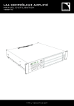
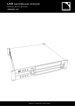
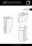
LA4 LA4 AMPLIFIED CONTROLLER User Manual Manual VERSION 1.3.0 1.3.0.32A .32A www. l- aco usti cs. co m www.l-aco u sti cs.co m 1 SAFETY WARNINGS All information hereafter detailed applies for the L-ACOUSTICS® LA4 Amplified Controller, designated in this section as ‘‘the product’’. 1.1 Symbol description 1.1.1 Symbols employed in this manual Throughout this manual the potential risks are indicated by the following symbols: The VOLTAGE symbol indicates a potential risk of electric shock that could be life threatening. In addition, the product may also be seriously damaged. VOLTAGE ! The WARNING symbol indicates a potential risk of physical harm to the user or people within close proximity to the product. In addition, the product may also be damaged. WARNING ! The CAUTION symbol notifies the user about information to prevent possible product damage. CAUTION ! The IMPORTANT symbol is a notification of an important recommendation of use. IMPORTANT 1.1.2 Symbols indicated on the product As the product is an electrical device, it represents potential hazard for the user. For this reason the user may pay particular attention to the symbols that are indicated on the product’s cover: ! CAUTION RISK OF ELECTRIC SHOCK DO NOT OPEN WARNING: RISK OF HAZARDOUS ENERGY SEE OPERATING MANUAL CLASS 2 PERMITTED The lightning flashes symbols next to the 4-point Speakon® connector sockets indicates that the product can produce high output voltages that are potentially life threatening. Connections between the product and a speaker should always be done with an all ready-made lead. Never attempt to touch any exposed speaker wiring whilst the amplifier is operating without disconnecting the connector first from the product. LA4_UM_EN_1.3.0.32a www.l-aco u sti cs.co m 1 LA4 Amplified Controller USER MANUAL VERSION 1.3.0.32A 1.2 Important safety instructions 1. Read this manual 2. Heed all safety warnings 3. Follow all instructions 4. The user should never incorporate equipment or accessories not approved by L-ACOUSTICS® ! 5. Environments Use the product only in E1, E2, E3, or E4 environments according to EN55103-2 standard. IMPORTANT ! IMPORTANT 6. Radio interference A sample of this product has been tested and complies with the limits for the EMC (European Electro Magnetic Compatibility) directive. These limits are designed to provide reasonable protection against harmful interference from electrical equipment. However, there is no guarantee that interference will not occur in a particular installation. 7. Power cord caution Do not use the product if the power cord is broken or frayed. Protect the power cord from being walked upon or pinched - particularly at the plugs and the point where the power cord exits from the apparatus. VOLTAGE VOLTAGE 8. Mains supply Connect the product only to AC power outlets rated 120 / 230 V, 50 - 60 Hz. A specific 100 V, 50 - 60 Hz version exists for Japan. NEVER connect the product to two live wires of a 120 V three-phase circuit (in order to use it in the 230 V mode). 9. Thermal circuit breaker ALWAYS interconnect a thermal circuit breaker between the product and the mains supply. The circuit breaker current rating depends on the mains voltage rating as follows: 16 A for 230 V, 30 A for 120 V, and 36 A for 100 V. VOLTAGE VOLTAGE 10. Grounding The product may only be connected to a mains power supply fitted with a grounding-type outlet tied to earth; do not defeat the outlet earth pin as it connects the product to earth. If the local outlet is obsolete, consult an electrician. The product is fitted with a grounding-type plug; do not defeat the earth wire connecting the plug female contact to the product chassis. If the plug does not mate with the local outlet, replace the plug by following the convention described in section 6.3.3. 11. Lightning storm During lightning storms, disconnect the product from the mains power supply. Switching the product off does not disconnect the product from the mains power supply. Disconnecting can only be achieved by removing the plug from the mains outlet. VOLTAGE LA4_UM_EN_1.3.0.32a www.l-aco u sti cs.co m 2 VOLTAGE ! 12. Interconnections When connecting the product to other equipment, turn off the power and unplug all of the equipment from the supply source. Failure to do so may cause an electric shock and serious personal injury. Read the user manual of the other equipment carefully and follow the instructions when making the connections. Do not connect a speaker output in parallel or series with any other amplifier’s output. Do not connect the speaker outputs to any other voltage source, such as a battery, mains source, or power supply, regardless of whether the product is turned on or off. WARNING 13. Over power risks The product is very powerful and can be potentially dangerous to both loudspeakers and humans alike. Even when using the product’s front panel attenuator to reduce the gain, it is still possible to reach full output power if the input signal level is high enough. ! 14. Ventilation Openings in the product cabinet are provided for ventilation to ensure reliable operation of the product by protecting it from overheating. These openings must not be blocked or covered. This product should be installed in accordance with the manufacturer instructions given in this manual. CAUTION ! 15. Heat Do not operate the product near any heat source, such as radiators or other devices. CAUTION 16. Water and moisture To prevent fire or shock hazard, do not expose the product to rain or moisture. Do not use the product near water. Do not operate the product while wet. VOLTAGE 17. Interference with external objects and/or liquids Never push objects of any kind into the product through openings as they may touch dangerous voltage points or short out parts that could result in a fire or electric shock. Never spill liquid of any kind on the product. VOLTAGE ! CAUTION ! CAUTION 18. Cleaning Unplug the product from the mains power supply before cleaning. Do not use liquid or aerosol cleaners. Clean only with dry cloth. 19. Mounting instructions Do not place the product on an unstable cart, stand, tripod, bracket, or table. The product may fall and be seriously damaged, and may cause serious human injury. Any mounting of the product should follow the manufacturer instructions, and should use the mounting accessories recommended by the manufacturer, as described in this manual. LA4_UM_EN_1.3.0.32a www.l-aco u sti cs.co m 3 LA4 Amplified Controller USER MANUAL VERSION 1.3.0.32A ! 20. Conditions which require immediate service Refer all servicing to qualified service personnel. Servicing is required when the product has been damaged in any way such as: • Power supply cord or plug is damaged, CAUTION VOLTAGE ! • Liquid has been spilled or an object has fallen into the product, • The product has been exposed to rain or moisture, • The product was dropped or the housing is damaged, • The product does not operate normally. 21. Servicing and replacement parts Do not attempt to service this product as removing covers may expose to dangerous voltage or other hazards. The use of unauthorized replacement parts may result in injury and/or damage through fire, electric shock, or other electricity-related hazards. All service and repair work must be carried out by an L-ACOUSTICS® authorized dealer. When replacement parts are required, ensure that the dealer/distributor only uses replacement parts specified by the manufacturer. 22. Shipping Use the original packaging for shipping the product, unless it is mounted in a rack with the front and rear panels fixed to the rack, as described in this manual. CAUTION ! IMPORTANT 23. Manual Keep this manual in a safe place during the product lifetime. This manual forms an integral part of the product. Reselling of the product is only possible if the user manual is available. Any changes made to the product have to be documented in writing and passed on to the buyer in the event of resale. LA4_UM_EN_1.3.0.32a www.l-aco u sti cs.co m 4 1.3 EC declaration of conformity L-ACOUSTICS® 13 rue Levacher Cintrat Parc de la Fontaine de Jouvence 91462 Marcoussis Cedex France State that the following product: Amplified Controller, LA4 Is in conformity with the provisions of: Low Voltage Electrical Equipment Directive 73/23/EC Electro-Magnetic Compatibility Directive 89/336/EC Applied rules and standards: EN60065 (Electrical safety) EN55103-1 (Emission) EN55103-2 (Immunity) Established at Marcoussis, France, the 06/21/2007 Christophe Pignon LA4_UM_EN_1.3.0.32a www.l-aco u sti cs.co m 5 LA4 Amplified Controller USER MANUAL VERSION 1.3.0.32A 2 CONTENTS 1 1.1 1.2 1.3 SAFETY WARNINGS 1 Symbol description ............................................................................................................................................1 1.1.1 Symbols employed in this manual........................................................................................................1 1.1.2 Symbols indicated on the product .......................................................................................................1 Important safety instructions..............................................................................................................................2 EC declaration of conformity .............................................................................................................................5 2 CONTENTS 3 3.1 3.2 INTRODUCTION 8 ® Welcome to L-ACOUSTICS ............................................................................................................................8 Unpacking .........................................................................................................................................................8 4 4.1 4.2 SYSTEM APPROACH 9 Presentation ......................................................................................................................................................9 System configurations ........................................................................................................................................9 5 5.1 5.2 LA4 AMPLIFIED CONTROLLER 11 Front and rear panels.......................................................................................................................................11 Main features...................................................................................................................................................12 5.2.1 Simplified block diagram ...................................................................................................................12 5.2.2 DSP Architecture..............................................................................................................................12 5.2.3 A/D Converters................................................................................................................................13 5.2.4 Amplifier section...............................................................................................................................13 5.2.5 User interface...................................................................................................................................14 5.2.6 L-NET Remote Control Network.....................................................................................................14 5.2.7 Digital Audio Network......................................................................................................................14 5.2.8 LA NETWORK MANAGER PC Software..........................................................................................14 6 6.1 6.2 6.3 INSTALLATION 15 Mounting.........................................................................................................................................................15 Cooling............................................................................................................................................................16 Connecting to AC mains ..................................................................................................................................16 6.3.1 Operating voltage .............................................................................................................................16 6.3.2 Circuit breaker .................................................................................................................................16 6.3.3 Power plug and wiring ......................................................................................................................16 On/Off Switch .................................................................................................................................................17 Wiring .............................................................................................................................................................18 6.5.1 XLR input connectors.......................................................................................................................18 6.5.2 Speakon® output connectors ............................................................................................................19 6.5.3 L-NET Wiring...................................................................................................................................20 Power consumption ........................................................................................................................................20 Heat power calculation....................................................................................................................................20 6.4 6.5 6.6 6.7 7 7.1 7.2 7.3 6 OPERATION 21 Quick access....................................................................................................................................................21 7.1.1 Output channel Mute control............................................................................................................21 7.1.2 Input & Output Gain control.............................................................................................................22 7.1.3 Front panel Lock / Unlock control.....................................................................................................22 Main Screen.....................................................................................................................................................22 User interface menu ........................................................................................................................................24 7.3.1 Introduction......................................................................................................................................24 7.3.2 LOAD PRESET (user: 1 to 10, manufacturer: 11 to 99) .....................................................................25 7.3.3 STORE PRESET (User memories 1 to 10).........................................................................................26 7.3.4 DELETE PRESET (User memories 1 to 10).......................................................................................27 7.3.5 PRESET PARAMETERS.....................................................................................................................28 LA4_UM_EN_1.3.0.32a www.l-aco u sti cs.co m 6 7.4 7.5 7.6 7.7 7.3.6 CLEAR GROUP PARAMETERS ........................................................................................................29 7.3.7 OPTIONS ........................................................................................................................................30 On screen messages ........................................................................................................................................33 7.4.1 Start-up sequence.............................................................................................................................33 7.4.2 Shut-down sequence ........................................................................................................................33 7.4.3 Information.......................................................................................................................................33 7.4.4 Malfunctions .....................................................................................................................................34 LED display .....................................................................................................................................................35 7.5.1 Output signal display.........................................................................................................................35 7.5.2 L-NET LED ......................................................................................................................................35 7.5.3 Routing and input signal display .........................................................................................................36 Amplified controller protection systems...........................................................................................................37 7.6.1 Thermal Protection ..........................................................................................................................37 7.6.2 Mean Over-Current Protection - Fuse Protection.............................................................................37 7.6.3 DC Protection..................................................................................................................................37 7.6.4 Mains supply Under & Over-voltage Detection .................................................................................37 7.6.5 Mains supply Failure Detection .........................................................................................................37 7.6.6 Peak Over-Current Protection .........................................................................................................37 7.6.7 DSP & Operating system Error .........................................................................................................37 L-DRIVE: transducer protection system ...........................................................................................................38 8 8.1 8.2 8.3 CARE AND MAINTENANCE 39 Maintenance information .................................................................................................................................39 Filter cleaning ..................................................................................................................................................39 Troubleshooting ..............................................................................................................................................40 8.3.1 No power, no sound, or sound level too low ....................................................................................41 8.3.2 Poor sound quality............................................................................................................................42 8.3.3 Overheating .....................................................................................................................................42 9 SPECIFICATIONS LA4_UM_EN_1.3.0.32a 43 www.l-aco u sti cs.co m 7 LA4 Amplified Controller USER MANUAL VERSION 1.3.0.32A 3 INTRODUCTION 3.1 Welcome to L-ACOUSTICS® Thank you for purchasing the L-ACOUSTICS® LA4 Amplified Controller. This manual contains essential information on installing and operating the product correctly and safely. Read this manual carefully in order to become familiar with these procedures. As part of a continuous evolution of techniques and standards L-ACOUSTICS® reserves the right to change the specifications of the product and the content of this manual without prior notice. Please check the L-ACOUSTICS® web site @ www.l-acoustics.com on a regular basis for latest updates. Should the product require repair or if information about the warranty is needed, please contact an approved L-ACOUSTICS® distributor. The address of the nearest distributor is available on the L-ACOUSTICS® web site. 3.2 Unpacking Carefully open the shipping carton and check the product for any noticeable damage. Each L-ACOUSTICS® product is tested and inspected before leaving the factory and should arrive in perfect condition. If found to be damaged, notify the shipping company or the distributor immediately. Only the consignee may initiate a claim with the carrier for damage incurred during shipping. Be sure to save the carton and packing materials for the carrier's inspection. The LA4 package comprises one L-ACOUSTICS® LA4 amplified controller and two rear rack support brackets, as shown in Figure 1: Figure 1: The LA4 amplified controller and its two rear rack support brackets LA4_UM_EN_1.3.0.32a www.l-aco u sti cs.co m 8 4 SYSTEM APPROACH 4.1 Presentation The L-ACOUSTICS® LA4 Amplified Controller is at the heart of the L-ACOUSTICS® integrated system approach. It offers cutting edge loudspeaker amplification, DSP, network control, and comprehensive system protection in a single ergonomic package. The LA4 performance level fully optimizes all L-ACOUSTICS® speaker resources and delivers outstanding audio quality combined with the best possible transducer protection. All L-ACOUSTICS® loudspeaker systems will now benefit from the advanced and exclusive properties of the LA4 and LA8 control platforms. As a result of the integrated approach all L-ACOUSTICS® loudspeaker systems will be enhanced by the superior performance of high end electronic platforms, allowing perfect power matching combinations across the entire product range. Packaged in a compact 2U lightweight format chassis the LA4 platform has the following characteristics: 4.2 • A 4 channel high efficiency amplifier section fed by two inputs that can deliver up to 4 x 1000 Watts into 4 ohms yielding perfect power matching for a selected range of L-ACOUSTICS® speakers. • A DSP section featuring advanced filter algorithms (IIR and FIR) and an exclusive L-DRIVE protection system for the transducers, allowing optimum system performance. • A complete on board preset library stored in 89 memory locations to cover all principal loudspeaker system configurations for a selected speaker range, and 10 user memory locations. • An intuitive and ergonomic user interface plus display for all configuration settings and status information all fully accessible from the front panel. • Two I/O Ethernet ports to interconnect up to 253 units in multiple network topologies through the L-ACOUSTICS® L-NET network. In this case the controllers can be remotely monitored by the PCbased LA NETWORK MANAGER software (Windows® compatible). • Four 4-point Speakon® connectors for loudspeaker outputs. • A rear-panel plug-in card slot also allowing the LA4 to be ready for multi-channel digital audio networking implementation (this option will be available as a future development). System configurations Driving four amplifier output channels through a DSP offers a wide range of options when it comes to system configuration possibilities. The LA4 and LA8 onboard DSP preset libraries allow the Sound Engineer a high degree of flexibility through the use of the 6 following system template configurations: • 4 Way active mono system • 2 Channel stereo system (for subwoofers or passive enclosures) • 2 Way active stereo system • Hybrid mono system (for subwoofers and active enclosures) • Hybrid stereo system (for subwoofers and passive enclosures) • Cardioid mono subwoofer system Note: The LA4 and LA8 preset description sheets are available in the “Preset Libraries - User Manual” on the L-ACOUSTICS® web site @ www.l-acoustics.com. LA4_UM_EN_1.3.0.32a www.l-aco u sti cs.co m 9 LA4 Amplified Controller USER MANUAL VERSION 1.3.0.32A The LA4 onboard factory preset library covers L-ACOUSTICS® loudspeaker systems that require up to 800 Watts into 8 ohms or 1000 Watts into 4 ohms. The system approach developed by L-ACOUSTICS® consists of the elements needed to fully optimize the possible configurations. The main products associated to the LA4 are the following (see also Figure 2): 8XT, 12XT KIVA, ARCS® KILO SB118 LA NETWORK MANAGER XT range coaxial enclosures 2-way WST® systems Subwoofer extensions for KIVA Subwoofer enclosure Remote control software ETHERNET SWITCH (not provided) LA NETWORK MANAGER LA4 8XT 12XT KIVA KILO SB118 ARCS Figure 2: LA4 and associated systems LA4_UM_EN_1.3.0.32a www.l-aco u sti cs.co m 10 5 LA4 AMPLIFIED CONTROLLER 5.1 Front and rear panels Figure 3: LA4 amplified controller front & rear panels 1 2 3 4 5 6 7 8 On/Off Switch Anti-Dust Cover Input selection + Menu keys Output selection keys LOAD led Signal Presence led Level and CLIP bargraph LED L-NET Network Control led LCD screen Nav/Edit Encoder wheel LA4_UM_EN_1.3.0.32a 9 10 11 12 13 14 15 XLR Input Link connector XLR Input connector RJ45 L-NET Network sockets Digital Audio Network socket (available as a future development) Speakon® Output connectors Fan Grill AC power cord www.l-aco u sti cs.co m 11 LA4 Amplified Controller USER MANUAL VERSION 1.3.0.32A 5.2 Main features 5.2.1 Simplified block diagram The LA4 combines in a 2U lightweight chassis the resources of a 2 IN / 4 OUT DSP engine driving four channels of amplification, a flash memory for preset storage and management, a front panel user interface, a Fast Ethernet device for network remote control, high performance A/D-D/A converters for audio signals, and an optional digital audio card (this option will be available as a future development). The administration of the LA4 resources is performed by an embedded Operating System (Linux) while the autosensing SMPS (Switched Mode Power Supplies) allows weight and size reduction. Figure 4: LA4 simplified block diagram 5.2.2 DSP Architecture The new proprietary algorithms are allowing optimum performance and protection of each individual transducer of the L-ACOUSTICS® system in use for an even more natural, transparent, and realistic sound experience. • The engine is a SHARC 32 bit floating point DSP at 96 kHz sampling rate that offers an enhanced dynamic range by not generating calculation clips like other fixed point DSP. • A special engineering approach combining IIR and FIR filters generates a perfect linearization of phase curves and therefore a significant improvement of the system impulse response. • The 2 x 4 matrix architecture offers flexibility for various system configurations. • The L-DRIVE transducer protection system offers advanced protection by monitoring both excursion and temperature of the transducer (see section 7.7). • With 89 factory presets and 10 user memory locations the engineer is offered fingertip access to all the usual L-ACOUSTICS® speaker system configurations (see the “Preset Libraries - User Manual”). LA4_UM_EN_1.3.0.32a www.l-aco u sti cs.co m 12 Array Morphing + 5 band EQ 2x4 MATRIX Figure 5: DSP Architecture 5.2.3 A/D Converters The LA4 amplified controller is fitted with two cascaded 24 bit A/D converters with a sampling rate of 96 kHz allowing a ground-breaking encoding dynamic of 130 dB. 5.2.4 Amplifier section The LA4 amplifier section uses a Class H technology supporting the wide dynamic range encountered in live audio productions. The 4 channels can deliver up to 4 x 1000 Watts into 4 ohms yielding perfect power matching for a selected range of L-ACOUSTICS® speakers. The auto-sensing SMPS (Switched Mode Power Supply) offers better stability by associating two symmetrical power supplies. The power supply architecture optimizes the power resources distribution with respect to each amplifier output channel requirements. LA4_UM_EN_1.3.0.32a www.l-aco u sti cs.co m 13 LA4 Amplified Controller USER MANUAL VERSION 1.3.0.32A 5.2.5 User interface The front panel user interface features quick access functions for the 2 inputs and 4 outputs. The encoder wheel gives instant access to the user menus and the LCD display offers real time visualization of the system parameters. Navigation through the menu pages is fast and intuitive. Beside the standard on board factory preset library the engineer can design and store his own settings (initialized from a standard preset template) in one of the 10 available user memory locations (see Chapter 7). 5.2.6 L-NET Remote Control Network The proprietary L-NET network uses a high speed data transfer of 100 Mbit/sec for real time monitoring and control of each individual LA controller within a network of up to 253 units. Multiple network topologies such as daisy-chain, star, and hybrid are quickly and easily configurable with total flexibility in achieving the required system architecture. The physical connection between the PC and the controllers is managed with CAT5e U/FTP cable (or higher category) and the I/O Ethernet sockets located on the rear panel of the controller require industry standard RJ45 connectors. The use of a universal Ethernet switch is recommended for specific network topologies. Note: Please refer to the ‘‘LA NETWORK MANAGER - User Manual’’ for detailed operating instructions. 5.2.7 Digital Audio Network A slot located on the rear panel is designed to accept an optional L-DGA card (digital audio network). The slot is for the provision of an additional digital input module consisting of a 64 audio channel bus plus one extra channel dedicated to remote control and monitoring. The extremely low and predictable latency of this technology combined with proven real world reliability delivers stable and predictable results in all sound reinforcement applications. The L-DGA card is also for cascading several LA4 (and LA8) using the same type of cable as for the L-NET remote control network. The signal routing on the digital audio bus into any LA controller can be operated from the LA NETWORK MANAGER software. ! This option will be available as a future development. IMPORTANT 5.2.8 LA NETWORK MANAGER PC Software L-ACOUSTICS® LA NETWORK MANAGER provides network control and monitoring of both LA4 and LA8 controllers from a PC Windows®-operating system. The multiple window display gives an overall visualization of the network status, number and groups of controllers, and all the information related to the control and monitoring of the networked controllers. Real-time access to all settings such as Preset, Mute/Solo, Gain, Delay, Polarity, and Matrix can be done using the remote software interface. A contour EQ system is also available for quick and easy loudspeaker system frequency response setting. In particular, the original Array Morphing tool is dedicated to line source array systems. LA NETWORK MANAGER also features system stand-by and initialization control in addition to comprehensive visual monitoring of the audio signal paths and quick detection of any faults in the attached network. Note: Please refer to the ‘‘LA NETWORK MANAGER - User Manual’’ for detailed operating instructions. LA4_UM_EN_1.3.0.32a www.l-aco u sti cs.co m 14 6 INSTALLATION 6.1 Mounting The LA4 is two rack units high (2U) that can be mounted in an EIA-standard 19’’ rack (Figure 6). Four mount points are provided on the controller front panel for rack mounting. Use four screws and washers when mounting the controller to the front rack rails. Figure 6: Controller dimensions ! CAUTION During transport or while on tour it is essential that the LA4 controllers are rear supported in addition to the front panel mounting. Use the rear rack support brackets provided with the controller as described in Figure 7. Any mechanical damage to LA4 controllers used in portable applications without rear support will not be covered by warranty. Figure 7: Controller and rear rack support brackets LA4_UM_EN_1.3.0.32a www.l-aco u sti cs.co m 15 LA4 Amplified Controller USER MANUAL VERSION 1.3.0.32A 6.2 Cooling The amplified controller uses a forced air cooling system to maintain a low and even operating temperature. All fan cooled L-ACOUSTICS® amplified controllers have front to rear airflow. Therefore when stacking more than one unit in a rack, mount units directly on top of each other or close any open space in the rack with blank panels. If the controller is rack-mounted do not block front or rear air vents with front or back panels or doors. If this cannot be achieved a forced ventilation system has to be used. If the controller is installed in an enclosed rack the open area at the back of the controller must be at least 140 cm3 per controller. Ensure that the front filter system is clean and dust free (see section 8.2). ! CAUTION 6.3 Connecting to AC mains 6.3.1 Operating voltage Operating voltage range and frequency are indicated on the controller back panel. Only connect the controller to an appropriate AC circuit and outlet. If you are unsure of the output voltage of your AC mains please consult your local electrician. VOLTAGE The following table gives the LA4 Power Supply Data in nominal use (4 Ω, 1/8 of maximum output power [see section 6.6]): Table 1: LA4 Power supply data in nominal use Voltage (V) 100 120 / 230 * Mains Frequency (Hz) 50 - 60 50 - 60 Current (A) 26 22 / 12 Power Consumption (W) 1600 1600 * If the mains voltage value is more than 145 V the amplified controller will automatically start in the 230 V mode. On the contrary case the amplified controller will automatically start in the 120 V mode. 6.3.2 Circuit breaker ALWAYS interconnect a thermal circuit breaker between the product and the mains supply. VOLTAGE 6.3.3 The circuit breaker current rating depends on the mains voltage rating as follows: 16 A for 230 V, 30 A for 120 V, and 36 A for 100 V. Power plug and wiring The amplified controller is supplied either with a European, US, or Japanese AC power plug depending on the country of use. If the power plug is not appropriate it can be cut off and wired to a suitable plug in the following manner: Table 2: Power cord wiring color code Country Europe USA Japan LA4_UM_EN_1.3.0.32a Live Brown Black Black Neutral Blue White White www.l-aco u sti cs.co m Earth Green / Yellow Green Green 16 VOLTAGE Changing the plug must be done by qualified personnel only. The specific safety regulations of the country of use must be strictly applied. The plug must be approved for the specific voltage and current rating given in Table 1. The ground connection of the supplied AC power cord is a safety feature. Do not attempt to disable it by using an adaptor or by other methods. NEVER connect an amplified controller to two live wires of a 120 V three-phase circuit (in order to use it in the 230 V mode). VOLTAGE Note: Warranty will not cover damages caused by a wiring error. 6.4 On/Off Switch When the controller is switched on (Figure 8) a 20 seconds start-up procedure of internal tests is activated, as described in section 7.4.1. The controller is ready for use when the LCD displays the main screen (see section 7.2). When the amplified controller is switched Off the LCD flashes the ‘‘POWER OFF’’ and “WAITING SMPS” messages for several seconds until complete shut down (see section 7.4.2). Notes: In case of power loss the controller will restart automatically once the power has been restored, and reboot to the exact same state prior to power loss. The ‘‘Standby Mode’’ message (and the four LOAD LED lit [see section 7.5.1]) indicates that the controller has been put in the Standby Mode via the LA NETWORK MANAGER software. This standby status prevents any front panel control and operating. To cancel the Standby Mode and LA NETWORK MANAGER exclusive control, reboot the unit by switching it off and on again. The On/Off switch does NOT disconnect the amplified controller from mains. VOLTAGE On Off Figure 8: The On/Off switch LA4_UM_EN_1.3.0.32a www.l-aco u sti cs.co m 17 LA4 Amplified Controller USER MANUAL VERSION 1.3.0.32A 6.5 Wiring 6.5.1 XLR input connectors Two 3 pin male XLR input connectors are provided for channel A & B respectively as well as two 3 pin female XLR input link connectors wired in parallel on channel A & B (see Figure 9). XLR Input connectors are active balanced and wired according to IEC 268 as below: Pin 1 Ground (Shield) Pin 2 Hot (pos. signal) Pin 3 Cold (neg. signal) Figure 9: Input XLR connectors cabling The input impedance is high enough (22 kΩ, balanced) to allow daisy-chaining or multiple parallel input connections. To daisy chain amplified controllers use the male XLR connector (‘‘Link’’) to feed the input signal to the next unit in the signal chain. The headroom of the input circuits is high enough to accept the maximum output level from virtually any line level signal source (up to 22 dBu). Note: Symmetrical (balanced) shielded cables are highly recommended as balanced signals are less sensitive to AC hum and radio interference. Unbalanced lines may result in noise especially over long cable runs. LA4_UM_EN_1.3.0.32a www.l-aco u sti cs.co m 18 6.5.2 Speakon® output connectors Four 4-point Speakon® connectors, located at the back of the LA4 controller, are for loudspeaker connection and are wired as follows: Top Left: Pin 1+ Pin 1Pin 2+ Pin 2- Out 1+ Out 1 Out 2 + Out 2 - Top Right: Pin 1+ Pin 1Pin 2+ Pin 2- Out 3 + Out 3 Out 4 + Out 4 - Bottom Left: Pin 1+ Pin 1- Out 2 + Out 2 - Bottom Right: Pin 1+ Pin 1- Out 4 + Out 4 - Figure 10: Output speakers connections (signal path) ! Before connecting a loudspeaker system please refer to the specified speaker manual for further instructions. As a general guideline, active speakers only use top left & top right Speakon® outputs, while passive or subwoofer speakers may use all Speakon® outputs. IMPORTANT ! To insure both high performance and safety L-ACOUSTICS® recommends the exclusive use of high-quality, fully insulated speaker cables made of stranded copper wire. In order to preserve a high damping factor it is desirable to keep loudspeaker cables as short as possible and with a gauge offering low resistance per unit length. IMPORTANT LA4_UM_EN_1.3.0.32a www.l-aco u sti cs.co m 19 LA4 Amplified Controller USER MANUAL VERSION 1.3.0.32A 6.5.3 L-NET Wiring The LA4 can be connected to a network of several controllers driven by the PC-based LA NETWORK MANAGER software. The connection is done using the I/O Ethernet sockets located on the LA4 rear panel using standard CAT5e U/FTP cables (or higher category) and RJ45 connectors (see Figure 11). Figure 11: L-NET RJ45 connector sockets for networking and remote control Note: The network is rated at 100 Mbps. The CAT5e U/FTP reference stands for a category 5 unshielded cable with foiled twisted pairs. 6.6 Power consumption The LA4 power requirements summarized in Table 3 (4 channels being driven at the same time) are dependent of load impedance and signal level characteristics: Table 3: LA4 Maximum Output Power versus Mains Input Power Load 4Ω 8Ω Maximum output power Number of Power channels 4x 1000 W 4x 800 W Mains input power and current draw 1/3 Output Power 1/8 Output Power IDLE (-5 dB) (-9 dB) 22 A / 3250 W 12 A / 1600 W 0.3 A / 70 W 17 A / 2550 W 9 A / 1350 W Values given for 230 V mains input. Multiply current values by 2 for 120 V. Multiply current values by approx. 2.3 for 100 V. If voltages outside a plus or minus 10 % range the maximum power is no longer guaranteed. Note: A third of the maximum output power corresponds to the worst case scenario of a program source using highly compressed music or pink noise with amplifier driven to clip level. An eighth of the maximum output power corresponds to a loud music program with a small dynamic range and 9 dB of headroom (IEC standard power rating). 6.7 Heat power calculation For example, let’s connect a 4 Ω load to each output channel of the controller: each output channel can now deliver up to 1000 W output power. Consider a standard use at 1/8 of full power (9 dB headroom). The power delivered per channel is then 1000 / 8 = 125 W, leading to a total power of 4 x 125 = 500 W for the controller. According to Table 3 the controller’s power consumption is 1600 W, the heat power produced is then 1600 - 500 = 1100 watts (difference between power consumption and output power). LA4_UM_EN_1.3.0.32a www.l-aco u sti cs.co m 20 7 OPERATION 7.1 Quick access The LA4 offers 3 quick access functions: Mute, Gain, and front panel locking. 7.1.1 Output channel Mute control Tapping (less than 0.3 Sec between clicks) one of the 4 output keys will either Mute or Unmute the corresponding output channel immediately. This function is accessible at all time and position in the Menu tree. The key is lit in blue when the corresponding output channel is Muted and not lit when the corresponding channel is unmuted (see Figure 12). This action automatically puts the LA4 in the Mute menu page. To leave the Mute menu page click on the ESC key. Figure 12: Output 1 is unmuted, all other 3 output channels are muted Notes: The Mute/Unmute quick access function is only accessible for outputs 1-4, not for input A & B. In default settings the outputs are muted and it is possible to set the gain before unmuting. LA4_UM_EN_1.3.0.32a www.l-aco u sti cs.co m 21 LA4 Amplified Controller USER MANUAL VERSION 1.3.0.32A 7.1.2 Input & Output Gain control Gain control is also available in quick access mode for both inputs (IN A & B) and outputs (OUT 1 to 4). From the main screen push and hold the chosen input or output key: the LCD will display the name of the selected channel and its gain value. Rotate the encoder wheel to set the gain value and simply release the key to return to the main screen. Figure 13: Setting the OUT 3 channel gain Notes: Quick access gain function is only available from the main screen. Depending on the selected factory preset the output gain might be locked by L-ACOUSTICS®. In that case the LCD displays a cross (X) instead of a numeric value. Gain values can be scaled at 0.1dB or 1dB resolution. To obtain 0.1dB resolution, simply rotate the encoder wheel. To obtain 1dB resolution, simultaneously push and rotate the encoder wheel. 7.1.3 Front panel Lock / Unlock control To lock the front panel (even the Mute function) and prevent any unintentional operation simply press and hold both IN A & IN B keys simultaneously until the message ‘‘DISPLAY LOCKED’’ is displayed. To unlock press and hold both IN A & IN B keys simultaneously until the message ‘‘DISPLAY UNLOCKED’’ is displayed. 7.2 Main Screen Once the LA4 start-up procedure has fully cycled (see section 7.4.1) the LCD will display the main screen with the following information: 1 2 3 4 5 Figure 14: Main screen LA4_UM_EN_1.3.0.32a www.l-aco u sti cs.co m 22 1. Preset Allocation (1 to 99) 11 to 99: Allocated OEM memory locations for L-ACOUSTICS® factory presets. 1 to 10: Allocated memory locations for user presets (initialized from a factory preset). The STORE PRESET function (see section 7.3.3) is only available for these first 10 user memory locations. Notes: The onboard preset library update can be done by up-loading a preset library using via the IN L-NET port located at the back of the controller (refer to the ‘‘LA NETWORK MANAGER - User Manual’’). This update will be available for download on the L-ACOUSTICS® web site @ www.l-acoustics.com. Onboard preset library version is displayed during the start-up procedure and can also be found in the OPTION menu section (see section 7.3.7). 2. Output Type & Channel assignment Directly above each output key the LCD displays the ‘‘_’’ label where: • The first 2 digits indicate the type of transducer to be connected to the corresponding output channel: PA: passive enclosure LF, HF: low or high frequency transducer, respectively SB: subwoofer enclosure SR: reversed subwoofer enclosure for ‘‘cardioid’’ applications • The last digit indicates which input channel the output is driven by: A: Output driven by input A B: Output driven by input B +: Output driven by the sum of input A and input B -: Output driven by the difference between input A and input B 3. Current preset Name The preset name can directly come from the current OEM preset library (refer to the “Preset Libraries User Manual”) or can be modified by the user if prior stored in a user memory location (section 7.3.3). Note: CUSTOM presets are also editable using the LA NETWORK MANAGER software (refer to the ‘‘LA NETWORK MANAGER - User Manual’’). 4. IP address (1 to 253) The IP address identifies the current controller within a network of multiple LA4 and/or LA8 units. IP address description and setting are detailed in the OPTION menu (section 7.3.7). 5. Star sign (*) The star sign is displayed when parameter settings have been modified from the original preset stored in memory. Notes: If a power loss occurs for less than 10 seconds while the controller is on and no signal is passing through the amp, the controller will remain on and will not shut down. If the power has been lost for more than 10 seconds, the controller will shut down but all parameters will be restored to same state as before shutting down when the controller switches on again. LA4_UM_EN_1.3.0.32a www.l-aco u sti cs.co m 23 LA4 Amplified Controller USER MANUAL VERSION 1.3.0.32A 7.3 User interface menu 7.3.1 Introduction The user interface gives access to 6 menus that are briefly described in the following list. Please refer to sections 7.3.2 through 7.3.7 for detailed instructions. Menu LOAD PRESET STORE PRESET DELETE PRESET PRESET PARAMETER Function Load and initiate a preset (memories 1 to 99). Save user preset & parameters (memories 1 to 10). Delete a preset (memories 1 to 10). Control and set Mute/Unmute, Gain, delay, and polarity (when available). CLEAR GRP PARAMETER Remove group parameters defined in the LA NETWORK MANAGER software (Name, Gain, Delay, and Contour EQ). OPTIONS Select the LA4 IP address, input signal source (analog or digital), delay unit, and LCD screen contrast. Provide real-time temperature and RMS output voltage for each amp channel. Display data like MAC ADDRESS, firmware, and onboard preset library version. The following procedure and Figure 15 show how to access one of these menus: 1. 2. 3. Press and release the encoder wheel. Rotate the encoder wheel clockwise or counterclockwise until the desired menu is selected. Press the OK key or the encoder wheel to enter menu or press the ESC key to return to the Main screen. Figure 15: Menu selection procedure LA4_UM_EN_1.3.0.32a www.l-aco u sti cs.co m 24 Arrows cursor convention and menu control To facilitate the navigation through menu control screens the LCD displays 2 types of arrow cursors: the Position cursor (top left) and the Selection cursor (top right). Position cursors: : Indicates the start of a menu and prompts the user to turn the encoder wheel clockwise to scroll down menu’s other functionalities. : Prompts the user to turn the encoder wheel clockwise or counterclockwise to scroll up and down menu’s other functionalities. : Indicates the end of a menu and prompts the user to turn the encoder wheel counterclockwise to scroll up menu’s other functionalities. Selection cursor: : Indicates another menu level or function, accessible by pressing the OK key or the Encoder wheel. Press the ESC key to return to the last menu. 7.3.2 LOAD PRESET (user: 1 to 10, manufacturer: 11 to 99) This LOAD PRESET menu is for loading a preset from the 99 on board memory locations: 11 to 99: Allocated OEM memory locations for L-ACOUSTICS® factory presets. 1 to 10: Allocated memory locations for user presets (initialized from a factory preset). To load a preset, select the LOAD PRESET menu and follow this procedure (see also Figure 16): 1. Turn the encoder wheel to scroll through the presets library. 2. Press the OK key or the encoder wheel to select the desired preset (or press the ESC key to cancel and return to the last menu). The LCD will display “ARE YOU SURE?” 3. Press the OK key or the encoder wheel to load the preset (or press the ESC key to cancel and return to the last menu). The preset will be loaded and activated and the LCD screen will display the preset information as described in section 7.2. LOAD PRESET KIVA 11:KIVA LOAD PRESET KIVA 12:KIVA_FI OK LOAD PRESET KIVA ARE YOU SURE ? ESC * OK 12:KIVA_FI 110 PA_A PA_A PA_B PA_B ESC LOAD PRESET 108aS118 85:108a_SB118 Figure 16: Loading a preset Note: The upper line of the LCD shows the preset family while the bottom line shows the preset name. LA4_UM_EN_1.3.0.32a www.l-aco u sti cs.co m 25 LA4 Amplified Controller USER MANUAL VERSION 1.3.0.32A * If the controller is assigned to a group (see section 7.3.6) the sequence is continued as follows: *OK CLEAR GRP PARAM ? Outputs muted OK 12:KIVA_FI 110 PA_A PA_A PA_B PA_B Group parameters cancelled and outputs muted 12:KIVA_FI 110 PA_A PA_A PA_B PA_B Group parameters still available ESC ESC Figure 17: Controller assigned to a group 7.3.3 STORE PRESET (User memories 1 to 10) The STORE PRESET menu is for storing a preset (including the user parameters) in the 10 available user memory locations. To store a preset, select the STORE PRESET menu and follow this procedure (see also Figure 18): 1. Turn the encoder wheel to scroll through the 10 available user memory locations. 2. Press the OK key or the encoder wheel to select the desired memory location (or press the ESC key to cancel and return to the last menu). The LCD will display “OVERWRITE ? ” 3. Press the OK key or the encoder wheel once again to overwrite (or press the ESC key to cancel and return to the last menu): the LCD will show “FILE NAME ?” 4. Name the new file (12 characters max): scroll through the characters by turning the encoder wheel, go to the next character by pressing the encoder wheel, finally confirm by pressing the OK key (or abort by pressing the ESC key). The preset will be loaded and activated and the LCD screen will display the preset information as described in section 7.2. Store User Preset 1: empty OK OVERWRITE ? 1: empty ESC OK Store User Preset 10: empty ESC +PUSH FILE NAME ? 1: My KIVA_FI FILE NAME ? 1: KIVA_FI ESC OK ESC 1: My KIVA_FI 110 PA_A PA_A PA_B PA_B Figure 18: Storing a preset Note: Modifying the name of a preset does not reset its basic characteristics, in particular the L-ACOUSTICS® factory locked parameters. LA4_UM_EN_1.3.0.32a www.l-aco u sti cs.co m 26 7.3.4 DELETE PRESET (User memories 1 to 10) The DELETE PRESET menu is for erasing a user preset previously saved in one of the 10 available user memory locations. To erase a user preset, select the DELETE PRESET menu and follow this procedure (see also Figure 19): 1. Turn the encoder wheel to scroll through the stored presets (from 1 to 10 depending on prior stored presets). 2. Press the OK key or the encoder wheel to select the desired preset (or press the ESC key to cancel and return to the last menu). The LCD will display “ARE YOU SURE ?” 3. Press the OK key or the encoder wheel to delete the preset (or press the ESC key to cancel and return to the last menu). The preset will be deleted and the LCD screen will display “PRESET DELETED”. When returning to the main screen the current preset will be displayed.* 4. Repeat steps 1 through 3 for all desired user presets to be deleted. Delete User Preset 1: My KIVA_FI OK ARE YOU SURE ? 1: My KIVA_FI * OK PRESET DELETED 1: My KIVA_FI ESC ESC 12: KIVA_FI 110 PA_A PA_A PA_B PA_B Figure 19: Deleting a user preset * For obvious reasons the system will not allow the user to delete the preset currently loaded. In this case the message ‘‘NOT ALLOWED’’ is displayed and the preset is not deleted (press the ESC key to return to the main menu). Note: If no user presets are stored the message ‘‘NO PRESET PRESENT’’ appears and the DELETE PRESET function is not accessible. LA4_UM_EN_1.3.0.32a www.l-aco u sti cs.co m 27 LA4 Amplified Controller USER MANUAL VERSION 1.3.0.32A 7.3.5 PRESET PARAMETERS The PRESET PARAMETERS menu is for setting the preset parameters (Mute & Unmute, Gain, Delay and Polarity [when available]) of each individual input (IN A & B) and output (OUT1 to OUT4) channels. To access preset parameters, select the PRESET PARAMETERS menu and follow this procedure (see also Figure 20): 1. Turn the encoder wheel to scroll through one of the seven preset parameters. 2. To change the preset parameters to the desired value press and hold the corresponding input or output key * and turn the encoder wheel (or press the ESC key to cancel and return to the last menu). 3. Release the key when the desired value is obtained. 4. Repeat the procedure to set another parameter (or press the ESC key to return to the main menu. * Set the input channel parameters by pressing and holding the IN A or IN B key, even if the key is not located directly below the value displayed on screen. In the following example the gain of input A is set at a value of 5.1 dB: Hold IN A GAIN IN (dB) 0 0 DELAY IN (ms) 0 0 GAIN IN (dB) 5.1 0 Release IN A GAIN IN (dB) 5. 0 ESC Same sequence as for GAIN IN with either IN A or IN B keys POLARITY IN + + MUTE OUT ON ON ON ON GAIN OUT (dB) 0 0 0 0 Same sequence as for GAIN IN with OUT 1 to OUT 4 keys DELAY OUT (ms) 0 0 0 0 POLARITY OUT + + + + Figure 20: Setting preset parameters Setting the gain value Gain values are adjustable between -60 dB and +15 dB at 0.1 dB or 1 dB resolution. To obtain 0.1 dB resolution, simply turn the encoder wheel. To obtain 1 dB resolution, push and turn the encoder wheel simultaneously. Setting the delay value Delay values are adjustable from 0 to 500 ms (172 m/564 ft at 20 °C) for the input channels and from 0 to 35 ms (12 m/39 ft at 20 °C) for the output channels. Delay unit can be set in the DELAY UNIT menu (see section 7.3.7). To obtain one hundredth resolution of the displayed value, simply turn the encoder wheel. To obtain one tenth resolution of the displayed value push and turn the encoder wheel simultaneously. Notes: Although not always displayed, decimal value for Gain and Delay settings are indicated by a dot. For example, ‘‘5’’ stands for the exact value 5, while ‘‘5.’’ stands for a value bracketed between 5.1 and 5.9. To see the actual value, press and hold the key corresponding to the selected Input or Output channel. Depending on the selected factory preset some parameters might be locked by L-ACOUSTICS®. In that case the LCD displays a cross (X) instead of a value. LA4_UM_EN_1.3.0.32a www.l-aco u sti cs.co m 28 7.3.6 CLEAR GROUP PARAMETERS The CLEAR GROUP PARAMETER function is for resetting to their nominal values all group parameters (Name, Gain, Delay, and Contour EQ) set in the LA NETWORK MANAGER software (see the ‘‘LA NETWORK MANAGER User Manual’’). To reset the group parameters, select the CLEAR GROUP PARAMETERS function and follow this procedure (see also Figure 21): 1. Press the OK key or the encoder wheel, the LCD will display “ARE YOU SURE ?” (or press the ESC key to cancel and return to the last menu). The “OUTPUT MUTED” message indicates that all outputs will be muted in the process. 2. Press the OK key or the encoder wheel once again to reset all group parameters (or press the ESC key to cancel and return to the last menu). All outputs will be muted and the LCD will return to the main screen. CLEAR GRP PARAM OK ARE YOU SURE ? OUTPUT MUTED OK 12:KIVA_FI 110 PA_A PA_A PA_B PA_B ESC ESC Figure 21: Resetting group parameters Notes: If the controller is not assigned to a group the message ‘’NO GROUP DEFINED’’ appears and the CLEAR GROUP PARAMETER function is not accessible. It is possible to check if a controller is part of a group and to identify its name by pressing and holding either the IN A or IN B key. The name of the group will appear at the bottom right of the LCD (Figure 22 shows that the controller belongs to a group named KIVALEFT). The group parameters remain active even if the controller is disconnected from the PC remote running LA NETWORK MANAGER (controller in the standalone mode), and they are not preset dependent (they will remain the same even if a new preset is loaded). Therefore, when getting a unit for a standalone application that has been previously used within a network, L-ACOUSTICS® recommends using the CLEAR GROUP PARAMETERS function in order to clear all group parameters as they cannot be seen and accessed via the front panel user interface. Figure 22: Controller’s group indication LA4_UM_EN_1.3.0.32a www.l-aco u sti cs.co m 29 LA4 Amplified Controller USER MANUAL VERSION 1.3.0.32A 7.3.7 OPTIONS The OPTIONS menu is for setting the LA4 IP address, input signal source (analog or digital), delay unit, and LCD screen contrast. It also gives real-time display of each amp channel temperature and RMS output voltage as well as displaying data like MAC ADDRESS, firmware version, and onboard preset library version. By selecting the OPTIONS menu and rotating the encoder wheel the user can have access to 9 different menu pages (see Figure 23). All 9 menu pages are fully detailed in the next sections. NETWORK ADDRESS 110 OK OK > 123 < OK DELAY UNIT ms MONITOR TEMP (°C) 64 65 NETWORK ADDRESS 123 ESC INPUT MODE ANALOG 65 NETWORK ADDRESS ESC DELAY UNIT > Meters < OK DELAY UNIT Meters ESC ESC 63 OUT RMS VOLTAGE 36 33 35 34 CONTRAST SCREEN OK CONTRAST SCREEN 100 % IDENTITY NUMBER OK CONTRAST SCREEN 35 % > 35 % < ESC ESC 00:1B:92:01:00:16 FIRMWARE VERS 1.3.0.32 PRESET VERSION V2.0 Figure 23: OPTION menu pages LA4_UM_EN_1.3.0.32a www.l-aco u sti cs.co m 30 NETWORK ADDRESS menu page It is possible to connect up to 253 LA4 or LA8 amplified controllers in multiple network topologies via the proprietary L-NET network. Each controller has to be identified within the network by its IP address (see notes below) typically of the format 192.168.1. . To change the value of the last 3 digits of the IP address (the other digits are fixed and cannot be changed) follow this procedure (see also Figure 23): 1. Select the NETWORK ADDRESS menu page by rotating the encoder wheel and press the OK key or the encoder wheel (or press the ESC key to cancel and return to the last menu). 2. Select the desired value (from 1 to 253) by turning the encoder wheel. Press the OK key or the encoder wheel to validate your setting (or press the ESC key to cancel and return to the last menu). As an example, in the Figure 23 the IP address 192.168.1.110 has been modified to 192.168.1.123. Note: The IP address is a unique Internet Protocol address to identify each controller within the network. One of these IP addresses has to be allocated to the network card of the remote computer running LA NETWORK MANAGER. L-ACOUSTICS® recommends using the last available IP address (192.168.1.254) for the computer Network card. INPUT MODE menu page The INPUT MODE menu page is for selecting the input source, either ANALOG or DIGITAL when the optional L-DGA card (digital audio network) is fitted. ! This option will be available as a future development. IMPORTANT Note: The input mode selected for each input channel can be displayed by pressing and holding the IN A or IN B tab. As an example, the top right part of the LCD screens in Figure 26 and Figure 27 show the ANALOG type selection (AN). DELAY UNIT menu page The DELAY UNIT menu page is for selecting whether the delay is displayed in milliseconds, feet or meters. To change this setting, follow this procedure: 1. Select the DELAY UNIT menu page by rotating the encoder wheel and press the OK key or the encoder wheel (or press the ESC key to cancel and return to the last menu). 2. Select the desired unit (ms, feet, or meters) by turning the encoder wheel. Press the OK key or the encoder wheel to validate your setting (or press the ESC key to cancel and return to the last menu). As an example, in the Figure 23 the delay unit has been changed from millisecond to meter. MONITOR TEMP menu page The MONITOR TEMP menu page displays the temperature of each individual amplifier channel circuit in Celcius (°C). As an example Figure 23 shows that the temperature of each output amplifier circuit is respectively 65, 64, 65, 63 °C. LA4_UM_EN_1.3.0.32a www.l-aco u sti cs.co m 31 LA4 Amplified Controller USER MANUAL VERSION 1.3.0.32A OUT RMS VOLTAGE menu page The OUT RMS VOLTAGE menu page displays the RMS voltage measured at each individual amplifier circuit output in Volts rms (Vrms). As an example, in Figure 23 the RMS voltage at OUT 1 to OUT 4 is respectively 36, 33, 35, 34 Vrms. CONTRAST SCREEN menu page The CONTRAST SCREEN menu page is for setting the LCD screen contrast. Change this setting by following this procedure: 1. Select the CONTRAST SCREEN menu page by rotating the encoder wheel and press the OK key or the encoder wheel (or press the ESC key to cancel and return to the last menu). 2. Select the desired value (between 0 and 100 %) by turning the encoder wheel. Press the OK key or the encoder wheel to validate your setting (or press the ESC key to cancel and return to the last menu). As an example, in Figure 23 the contrast has been changed from 100 % to 35 %. IDENTITY NUMBER menu page The IDENTITY NUMBER menu page displays the MAC (Media Access Control) address of the current controller. This address is the equivalent of a serial number and identifies the controller internationally. It is set by the manufacturer and cannot be modified. As an example Figure 23 shows the following MAC address: 00 :1B :92 :01 :00 :16. FIRMWARE VERS menu page The FIRMWARE VERS menu page displays the version of the firmware in use. As an example Figure 23 indicates the 1.3.0.32 firmware version. Note: Check the L-ACOUSTICS® web site @ www.l-acoustics.com on a regular basis for the latest firmware version and apply the instructions given in the ‘‘FIRMWARE_UPDATE_PROCEDURE.pdf’’ file embedded in the installation package. PRESET VERSION menu page The PRESET VERSION menu page displays the version of the preset library in use. As an example Figure 23 indicates the 2.0 preset library version. Note: Check the L-ACOUSTICS® web site @ www.l-acoustics.com on a regular basis for the latest preset library version and apply the instructions given in the ‘‘LIBRARY_UPDATE_PROCEDURE.pdf’’ file embedded in the installation package (exceptionally, the 2.0 version will automatically be installed with the 1.3.0.32 firmware). LA4_UM_EN_1.3.0.32a www.l-aco u sti cs.co m 32 7.4 On screen messages In this section are listed all the messages that can be displayed on the controller LCD screen. The display mode (standing or blinking) depends on the message type. 7.4.1 Start-up sequence When switched on, the controller goes through a start-up sequence coming with the 5 following messages: DISPLAY TEST/INIT L-ACOUSTICS LA4 PRESET VERSION 2.0 L-ACOUSTICS LA4 FIRMWARE VERS 1.3.0.32 IP : 192.168.1.110 SN:00:1B:92:01:02:1B MESSAGE Amp running 7.4.2 Testing sequence with all green LED momentarily lit. Controller type and preset library version display. Firmware version display. Controller IP address and Serial Number (MAC address) display. Start-up sequence succeeded. Shut-down sequence When switched off, the controller goes through a shut-down sequence coming with the following message: MESSAGE Power OFF MESSAGE Waiting SMPS 7.4.3 SMPS has shut down. Message flashing for several seconds until complete shut-down. If the controller is switched on again while this message is flashing, the controller will recover the operating state without going through the start-up sequence. Information MESSAGE Standby Mode LA4_UM_EN_1.3.0.32a Controller in Standby Mode (see section 6.4). www.l-aco u sti cs.co m 33 LA4 Amplified Controller USER MANUAL VERSION 1.3.0.32A 7.4.4 Malfunctions Malfunctions not leading to controller stop: HIGH TEMPERATURE : SIGNAL ATTENUATION Temperature of one of the 4 amp channel heat sinks reaching 85 °C. Input signals going into all amp channels attenuated (see section 7.6.1). MESSAGE Fuseprotect Too high main input current draw: fuse protection feature activated (see section 7.6.2). MESSAGE DC : Channel x DC voltage of plus or minus 3 V detected on the displayed amplifier output circuit (see section 7.6.3). MESSAGE Error on Channel x Error detected on the displayed amplifier output circuit: this circuit is muted and the others operate normally. Malfunctions leading to controller stop: ERROR Protect : CH x Fatal error occurred on the displayed amplifier output circuit: all amp circuits are muted for safety purposes. MESSAGE Waiting SMPS Main power supply not available. The controller will automatically return to normal state when the power supply has been recovered (“Amp running” message displayed). DSP ERROR AMP OFF Communication fault between the DSP and the Linux operating system (see section 7.6.7). LA4_UM_EN_1.3.0.32a www.l-aco u sti cs.co m 34 7.5 LED display 7.5.1 Output signal display Four bargraph displays are located on the front panel above the LCD screen (see Figure 24). By default they monitor the state of each of the 4 amplifier output channels via 6 different LED (LOAD, SIGNAL, -25dB, -10dB, -5dB, CLIP). Figure 24: The four bargraph displays LOAD LED The green LOAD LED is lit when a speaker is connected at the corresponding amplifier channel output and when the output power reaches 1 W (@ 4 Ω). SIGNAL LED The SIGNAL LED is lit when a signal is detected at the corresponding output of the amplified controller and when the output voltage reaches 100 mV. dB LED The green “-25 dB”, “-10 dB”, “-5 dB” LED are lit when the output voltage reaches respectively 25 dB, 10 dB, or 5 dB below the maximum level. CLIP LED The red CLIP LED is lit when the output voltage reaches the maximum level. 7.5.2 L-NET LED The green L-NET LED (Figure 25) is lit when the amplified controller is part of a network and controlled by the LA NETWORK MANAGER software (see the ‘‘LA NETWORK MANAGER - User Manual’’). Note: The front panel commands remain accessible. Figure 25: The green L-NET LED is lit LA4_UM_EN_1.3.0.32a www.l-aco u sti cs.co m 35 LA4 Amplified Controller USER MANUAL VERSION 1.3.0.32A 7.5.3 Routing and input signal display The four bargraph displays can also provide information about the signal routing between input and output channels for the current preset and about the input signal level. This information is accessed by pressing and holding either the IN A or IN B key (only available when the main screen is displayed). As an example (see Figure 26), pressing and holding the IN A key lits the OUT 1 and OUT 2 “LOAD” LED: this indicates that the IN A input is routed to OUT 1 & 2 output channels. The “SIGNAL” and “-25 dB” LED of the first bargraph display lit simultaneously, displaying the level of the signal delivered at the A input of the controller. Note: The SIGNAL LED lits when the input voltage reaches -37.8 dBu (10 mV) and the CLIP LED lits when the input voltage reaches 22 dBu (9.8 V). IN A channel input level IN A signal routed to OUT 1 and OUT 2 channels Figure 26: IN A input channel routing and level information Similarly, as shown in Figure 27, pressing and holding the IN B key lits the OUT 3 and OUT 4 output “LOAD” LED: this indicates that the IN B input is routed to OUT 3 & 4 output channels. The “SIGNAL” and “-25 dB” LED of the OUT 2 bargraph display are simultaneously lit, displaying the level of the signal delivered at the B input of the controller. IN B channel input level IN B signal routed to OUT 3 and OUT 4 channels Figure 27: IN B input channel routing and level information Notes: The input mode (analog or digital) for each input channel is displayed on the top right part of the Figure 26 and Figure 27 screens (see the INPUT MODE menu page in the OPTIONS menu [section 7.3.7]). Rotating the encoder wheel while pressing and holding either the IN A or IN B key allows setting the input gain of the corresponding input as described in section 7.1.2. LA4_UM_EN_1.3.0.32a www.l-aco u sti cs.co m 36 7.6 Amplified controller protection systems Most of the protection systems that insure the integrity of the unit’s electronic vital parts are managed by the Operating System (OS). This allows real-time monitoring and optimal performance with a high level of safety even under extreme conditions. 7.6.1 Thermal Protection The fans associated to the heat sinks operate permanently, but as long as the temperature remains below 40 °C they run at their slowest speed and can hardly be heard. The highest detected temperature controls the speed of the fans. Above 40 °C the speed is increased until it reaches its maximum value. If the OS detects a temperature of more than 85 °C at the heat sinks the input signals delivered at all amplifier output channels are attenuated. The input signal is muted if the temperature exceeds 96 °C. 7.6.2 Mean Over-Current Protection - Fuse Protection The average mains current can peak temporarily depending on load impedance and type of signal, at values several times higher than the nominal value supported by the fuse protection. In order to avoid shut-down of the power supply (due to the over-current protection of the SMPS controller) the amplitude of the input signals will be limited. 7.6.3 DC Protection Each of the four amplifier channel outputs is monitored at all time for sustained presence of DC voltage above the 3 V threshold. If such threshold is exceeded for a long time at any of the outputs the main SMPS or the concerned output channel will be automatically switched off. 7.6.4 Mains supply Under & Over-voltage Detection The LA4 amplified controller uses an auto-sensing SMPS for mains input voltages 120/230 V, 50-60 Hz (100 V version exists for Japan). The mains supply voltage is monitored at all times for under & over-voltage: the auto-sensing SMPS will automatically switch off if the mains supply voltage leaves the nominal voltage window. When the mains supply voltage returns to an acceptable value a soft start sequence will be automatically engaged. 7.6.5 Mains supply Failure Detection The mains supply is monitored at all times for mains cycles discontinuity. If the mains supply skips about 2 cycles the auto-sensing SMPS will switch off. A soft start sequence will be automatically engaged when the mains supply returns to nominal state. 7.6.6 Peak Over-Current Protection The amplified controller main SMPS current is continuously monitored. If an over-current is detected the main SMPS is immediately switched off. Should there be an internal failure this feature prevents other parts from being damaged. The output stages also are continuously monitored for possible current surges. There are two limiting levels of overcurrent depending on output voltage (limitation will be set automatically). This approach improves reliability without degrading sound quality. 7.6.7 DSP & Operating system Error Communications errors or disconnection between the DSP and the Linux operating system could corrupt parameter settings, which could in turn damage the speaker system in use. Therefore, the user should reboot the amplified controller by switching it off and on to try to restore the communication between the DSP and the operating system. LA4_UM_EN_1.3.0.32a www.l-aco u sti cs.co m 37 LA4 Amplified Controller USER MANUAL VERSION 1.3.0.32A 7.7 L-DRIVE: transducer protection system The new L-DRIVE protection provides a dual analysis of both signal intensity and voltage in real time and RMS. Under extreme condition, when component membranes reach the over-excursion zone or if the coil ensemble temperature reaches a critical point, L-DRIVE is activated and acts as a power regulator. As a result, the amount of power delivered to each channel is adjusted to the power handling capacity of each individual transducer on the relevant channel. Thereby, this optimizes the power resources of the system in use while preserving the highest available dynamic range. LA4_UM_EN_1.3.0.32a www.l-aco u sti cs.co m 38 8 CARE AND MAINTENANCE 8.1 Maintenance information L-ACOUSTICS® amplified controllers are quality units and should provide years of trouble-free services when operated under normal conditions. The only maintenance required is to clean the anti-dust cover on a regular basis (see section 8.2). In some cases it may be necessary for authorized service personnel to clean the inside of the controller, especially after long operation periods in very dusty or cracked-oil smoke machine environments. Cleaning and servicing the inside of an amplified controller must be done by qualified personnel only. VOLTAGE Any controller showing any sign of defect must immediately be put aside and withdrawn from use to be inspected by qualified service personnel. VOLTAGE ! During the decommissioning process of the amplified controller all legally prescribed rules and procedures must be adhered to. IMPORTANT 8.2 Filter cleaning ! IMPORTANT The air intake on the LA4 front face is fitted with a removable filter system. If the filter becomes clogged the unit will not cool as efficiently as it should, resulting in reduced output power level performances. To clean or change the foam filter follow this procedure (see Figure 28): 1. Unclip the molded front frame by pulling on it. 2. Clean (with mild dishwashing detergent or soap) or change the foam filter. 3. Replace the foam filter (when dry). 4. Align the molded front frame with its 2 clip aperture and push back into place. LA4_UM_EN_1.3.0.32a www.l-aco u sti cs.co m 39 LA4 Amplified Controller USER MANUAL VERSION 1.3.0.32A Foam filter Front frame Figure 28: LA4 filter assembly 8.3 Troubleshooting This section provides flowcharts to assist the user in troubleshooting problems with the LA4 amplified controller. The keys for interpretation of the flowcharts are the following: Symptom Question Remedy Comment Note: The flowcharts cannot cover every possible scenario the user may encounter. LA4_UM_EN_1.3.0.32a www.l-aco u sti cs.co m 40 8.3.1 No power, no sound, or sound level too low No power, no sound, or sound level too low Check if AC outlet works, connect the AC plug, switch the power on. Reboot the controller by switching it off and on again to cancel the Standby Mode No LCD screen lit? No Power switch on, AC plug connected, AC outlet working? The controller is in Standby Mode and controlled by LA NETWORK MANAGER software (see section 7.3.6) Yes Contact a local distributor for service Yes No No Firmware being updated? Yes Yes Wait 4 min for the updating sequence to be completed L-NET LED lit? No Main screen displayed? No Message ‘‘STANDBY MODE’’ displayed and 4 LOAD LED lit Displayed message on screen? Yes Any other message displayed (see section 7.6) Yes Signal LED blinking? Yes Speaker cables connected? Yes Check speaker cables and/or speakers No No Plug speaker cables on both sides Outputs muted? Yes Unmute the outputs No Output gain too low? * screen Yes Set output gain higher value * Press and hold either OUT 1 to OUT 4 keys to check the corresponding output gain values (see section 7.1.2). No Signal input presence? ** No Check level at signal source and secure XLR wiring on both sides ** Press and hold either IN A or IN B keys to check if the corresponding input signal LED are blinking or not (see section 7.5.3). Yes Contact a local distributor for service LA4_UM_EN_1.3.0.32a www.l-aco u sti cs.co m 41 LA4 Amplified Controller USER MANUAL VERSION 1.3.0.32A 8.3.2 Poor sound quality 8.3.3 Pour sound quality Controller’s output channels clipping? Overheating Yes Set output and/or input gain lower values * Filter clogged? Yes Clean or replace filter (see section 8.2) No No Controller’s input channels clipping? ** Yes Lower input signal source level Controller getting enough cool air? No Yes No Hum or Buzz? Overheating Yes Check signal XLR cables and connections on both sides Controller operating within rated impedance? No Yes Speaker cables correctly wired? *** No Check speakers cabling No See section 6.2 for information on how to achieve cooling of the controller Check that nothing causes a short circuit at the controller's outputs, e.g faulty cabling or a speaker component short circuit in the voice coil. Check that the number of enclosures wired in parallel to the same controller output is not too high. Contact local distributor for service Yes Speakers operating normally? No Check speaker and speaker cables for fault Yes Source signal clear and undistorted? No Check source signal Yes Contact local distributor for service * Press and hold either OUT 1-4 / IN A / IN B keys to check the corresponding output and input gain values (see section 7.1.2). ** Press and hold either IN A or IN B keys to check the corresponding input signal levels (see section 7.5.3). *** For example, check if LF and HF connections have not been inverted when cabling an active enclosure. LA4_UM_EN_1.3.0.32a www.l-aco u sti cs.co m 42 9 SPECIFICATIONS Output power EIA (1 % THD, 1 kHz, all channels driven) 4 x 800 W @ 8 Ω (4 x 930 W peak) / 4 x 1000 W @ 4 Ω (4 x 1600 W peak) Max output voltage 125 V (Peak voltage, no load ) Circuitry Bipolar, Class H 2-step high efficiency circuit Digital Signal Processor Two cascaded 24 bit A/D converters (130 dB dynamic range) (DSP) DSP SHARC 32 bit / floating point, 96 kHz sampling rate Latency 3.9 ms Frequency range 10 Hz–30 kHz (-0.1/+0.15 dB @ 8 Ω) Distortion THD+N (typical) < 0.03 % (20 Hz-10 kHz, 8 Ω, 11 dB below rated power) Output dynamic range 112 dB (20 Hz-20 kHz, 8 Ω, A-weighted) Amplification gain 32 dB Noise level -73 dBV (20 Hz–20 kHz, 8 Ω, A-weighted) Input impedance 22 kΩ (balanced) Max input level 22 dBu (balanced, THD 1 %) Channel separation > 80 dB (@ 1 kHz) Damping factor > 400 (8 Ω, 1 kHz and below) Mains input power and current draw (all channels driven) Maximum output power Number of Load Power channels 4Ω 4x 1000 W 8Ω 4x 800 W Mains input power and current draw 1/3 Output 1/8 Output Power IDLE Power (-5 dB) (-9 dB) 22 A / 3250 W 12 A / 1600 W 0.3 A / 70 W 17 A / 2550 W 9 A / 1350 W Values given for 230 V mains input. Multiply current values by 2 for 120 V. Multiply current values by approx. 2.3 for 100 V. If voltages outside a plus or minus 10 % range the maximum power is no longer guaranteed. 120/230 V AC (±10 %), 50 - 60 Hz 100 V AC (±10 %), 50 - 60 Hz (for Japan) Temperature monitoring of transformers and heat-sinks, inrush-current limitation, mains supply failure and over-voltage detection, output DC protection, output over current protection Transducers protection L-DRIVE Thermal and over excursion monitoring Fan 2 temperature dependent speed-controlled axial fans Indicators LED for Load, Signal, Level (-25 dB, -10 dB, -5 dB), Clip, L-NET, and Mute Input and link connectors (2 channels IN A, IN B) 2 x 3-pin XLR male and female per channel, pin 2 = hot (+) Output Connectors (4 channels OUT 1 to OUT 4) 1 x 4-point Speakon® connector per output channel L-NET connectors 2 in/out Fast Ethernet RJ45 connectors Options L-DGA network digital audio card (available as a future development) Dimensions (W x H x D) 483 x 88.1 (2U) x 428 mm / 19 x 3.5 (2U) x 16.8 inch Operating voltage Circuits protection Weight Finish LA4_UM_EN_1.3.0.32a 11.1 kg / 24.5 lbs black and anthracite gray www.l-aco u sti cs.co m 43 www.l-aco u sti cs.co m www.l-aco u sti cs.co m Document Reference: LA4_UM_EN_1.3.0.32a _________________ © Copyright 2009 by L-ACOUSTICS® Parc de la Fontaine de Jouvence, 91462 Marcoussis cedex, France _________________ Printed on recycled paper Distribution date: August 26th, 2009 www.l-aco u sti cs.co m