1
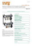
Model V45 Manual
Parts, Safety, Operation
& Maintenance
Form No. M1017-POMS
Revision 6
November 2001
Page 1
Model V45
Quick Reference
Quick Reference Parts
Qty.
DESCRIPTION
Item
Part Number Ref #
630
640
700
790
800
880
930
830
840
850
870
86383809
86382454
86422714
86588605
86474897
86509932
86576303
86422763
86362837
86378353
86385937
82747
82325
93598
N/A
94464
96567
97052
93548
76975
81137
83172
1
1
1
1
1
1
2
4
2
2
2
Strike piston
Cylinder
Spacer
Front guide
Upper chuck bushing
Lower chuck bushing
Tool retaining pin
Lock
Spring
Spring guide
Snap ring
Piston de frappe
Cylindre
Entretoise
Guide avant
Douille supérieure
Douille inférieure
Axe de retenue
Verrou
Ressort
Guide ressort
Jonc
490
500
510
520
950
960
86231644
86238466
86352481
86355500
86594785
86477163
7294
12817
73008
74256
N/A
94613
1
2
1
1
4
4
Fittings for auto greaser
Knee piece axle
Equal lip seal
Tight seal
Knee piece 3/8" NPTF
Side rod bolt
Side rod nut
Axe de genouillère
Joint à lèvres égales
Joint d'étanchéité
Genouillère 3/8" N
Vis d'assemblage
Ecrou
1071
1072
1080
86510146
86510112
86385572
96584
96582
83109
1
8
1
1070A 86510286
1072A 86510310
1080A 86385606
96597
96601
83112
1
8
1
Standard/Soundproof Cradle
110/140
86582152
N/A
120/150
86592490
N/A
20
86576444
97064
30
86307493
51743
40
86486909
95041
50
86506961
96432
60/90
86473048
94346
70/100
86473030
94345
80/110
86576436
97063
90/120
86307493
51743
100/130
86510005
96574
1150
Page 2
86492246
86492238
86481066
86392537
86265048
86241403
95295
95294
94712
84672
26428
14826
Upper suspension
Support disk
Screw, UNF 1 1/8”
Shock absorber
Upper soft
Support disk
Screw, UNF 1 1/8”
Shock absorber
Lower suspension
2
2
16
32
2
2
4
4
14
56
14
1
1
1
1
1
1
Disque d'appui
Vis CHc UNF 1 1/8”
Amorlisseur
Disque d'appui
Vis CHc UNF 1 1/8”
Amortisseur
Absorber
Bar
Wear plate bolts
Washer "two mounted at a time"
Guiding slipper
Guiding slipper
Plastic plug
Plastic plug
Screw UNF 1”
Washer "two mounted at a time"
Fixing cap nut
Moil point
Chisel
Seal kit
H.P. Diaphragm
Inflating screw
Inflating ring
Amortisseur
Barrette
Rondelle "montees par deux"
Patin de guidage
Patin de guidage
Bouchon plastique
Bouchon plastique
Vis UNF 1 "
Rondelle "montees par deux"
Ecrou H
Broche pic
Broche burin
Pochette rechange
H.P. Membrane d'accumulateur
Vis de gonflage
Bague BS
Model V45
Quick Reference
Quick Reference Torques
Part Number Ref #
DESCRIPTION
Assembly Side Rods
86594785
N/A
86477163
94613
Side rod bolt
Nut
Bracket Cap Bolts
86576436
97063
Fixing cap bolts
480 ft-lbs.
Wear plate Bolts
86576444
97064
Wear plate bolts
650 ft-lbs.
84667
81958
26428
90181
H.P. accumulator
Accumulator bolts
Inflation screw
Accumulator fixing bolts
725 psi charge pressure
370 ft-lbs.
16 ft-lbs.
660 ft-lbs.
Pull the nuts to 290 ft-lbs and release.
Pull the nuts to 150 ft-lbs in a crisscross
pattern. Align the notches. Next, pull five
more flats: Two flats, two flats and one flat
in a crisscross pattern. Go 1/4” past notch
and release to remove pretwist in rod.
Accumulator
86392487
86381340
86265048
86413457
Page 3
Model V45
Table of Contents
Forward
Avant Propos
5
Safety
Securite
S1
Ten Commandments
Dix Commandements
O1
Overall Dimensions
Encombrement
O2
Technical Specifications
Caracteristiques Techniques
O3
Mounting
Montage
O6
Tool Mounting
Montage de Outil
O8
Operation & Adjustment
Utilisation & Reglage
O10
Maintenance
Entretien
O13
Underwater Operations
Sous - Marine les Fonctionnements
O15
Tool Guide
Guide Outil
O16
Parts List
Pieces Detachees
P3
Accessories
Accessoires
P10
Trouble Shooting
Incidents Techniques
M1
Grease Station
Centrale de Graissage
G1
Page 4
Model V45
Forward
FOREWORD
AVANT PROPOS
The contents of this manual are considered to be
proprietary and confidential to TRAMAC and should
not be reproduced without prior written permission
from TRAMAC.
Le contents de ce manuel est considéré comme
appartenant à TRAMAC et comme confidentiel, il ne
doit pas être reproduit sans I'autorisation écrite
préalable de la société TRAMAC
Nothing contained in this document is intended to
extend any promise, warranty or representation,
expressed or implied regarding the TRAMAC products described herein. Any such warranties or other
terms and conditions of sale of products shall be in
accordance with the standard terms and conditions
of sale of such products, which are available upon
request.
Aucun élément du contenu de ce document n’est
entendu comme représentant aucune promesse,
garantie, ni représentation, ni explicates, ni
implicites, eut égard aux produits TRAMAC qui y
sont décrits. Toute garanties de cette nature ou tout
autres termes et conditions de vente des produits,
doivent être conformes aux termes et conditions
standard de vente de la société TRAMAC, termes
et conditions que l'on pourra obtenir sur demande.
This manual contains instructions and technical
data to cover all routine operations and scheduled
maintenance tasks by operation and maintenance
staff. Major overhauls are outside the scope of this
manual and should be referred to an authorized
TRAMAC service department.
The design specification of this machine has been
certified as complying with E.C. directives. Any
modification to any part is absolutely prohibited and
will result in the CE certification and marking being
rendered invalid.
TRAMAC reserves the right to make changes and
improvements to products without notice and without incurring any obligation to make such changes
or add such improvements to products sold previously.
Ce manuel contient des instructions et des données
qui couvrent toutes les opérations et les tdches de
maintenance régulière à effectuer par le personnel
d'exploitation et de maintenance. Les révisions
générales sortent du cadre de ce manuel et doivent
être renvoyées à un service d'entretien agréé TRAMAC.
Les spécifications de cet appareil ont été homologuées comme étant conformes aux directives de
la CEE. Toute modification dune pièce quelconque
est absolument interdite et auralt pour conséquence
l'invalidation de I'homologation CE.
La société TRAMAC se réserve le droit d'apporter
des modifications ou d'ajouter des perfectionnements aux produits sans préavis et sans encourir
en quoi que ce soit l'obligation d'apporter de telles
modifications ni d'ajouter de tels perfectionnements
aux produits vendus antérieurement.
Page 5
Model V45
Safety
WARNING!
ATTENTION!
WARNING! - Pressurized component or system.
ATTENTION! - Composant ou
systéme sous pression
WARNING! - Pressurized vessel
(accumulator).
WARNING! - Consult the operation and
maintenance manual before
beginning any maintenance.
ATTENTION! - Consulter le
manuel d'utilisation et d'entretien avant d'entreprendre toute
interventions.
ATTENTION! - Récipient sous
pression (accumulateur)
Lifting point.
Point de levage.
WARNING! - For operating temperature below
0º C, consult the operation and maintenance
manual.
0º C
ATTENTION! - Pour l'utilisation en dessous de
0º C, consulter le manuel d'utilisation et
d'entretien.
WARNING!
- Risk of flying chips of rock
- Keep clear, wear a helmet and
safety glasses.
ATTENTION!
- Risques de projections
- Rester à distance, porter un
casque et des lunettes de sécurité.
Page S1
Model V45
Safety
SAFETY
SECURITE
WARNINGS
ATTENTION
"Warnings" call attention to instructions which must
be followed precisely to avoid injury or death.
L'indication "ATTENTION" précise que les instructions doivent être suivies absolument pour éviter
tout accident grave.
CAUTION
PRECAUTIONS
"Caution" calls attention to instructions which must
be followed precisely to avoid damaging the product, process or its surroundings.
L'indication "PRECAUTION" précise que les
instructions doivent être suivies absolument pour
éviter d'endommager le produit, la procédure ou
son environnement.
NOTES
NOTES
Notes are used for supplementary information.
L'indication "NOTE" donne des compléments
d'information.
SAFETY PRECAUTIONS
PRECAUTION POUR LA SECURITE
All mechanical equipment can be dangerous when
used without care or if it is in bad condition.
Tous les appareils mécaniques peuvent être dangereux s'ils sont utilisés sans précautions ou s’ils
sont en mauvais état d'entretien.
Ensure that the operator reads and understands the
decals and consults the manuals before maintenance or operation.
Vérifier que l'opérateur lise et comprenne les étiquettes, consulte les manuels avant toute opération
et maintenance.
Ensure that the operation and maintenance manuals remain at operator's disposal.
Assurer vous que le manuel d'exploitation et de
maintenance reste à la disposition de l'utilisateur.
Ensure that maintenance personnel are adequately
competent and have read the maintenance
manuals.
Assurer vous que les personnels sont formés dune
manière adéquate, qu'ils sont compétents et qu'ils
ont lu les manuels de maintenance.
Safety is not only a matter of warnings. Every time
the operator is working with the breaker, the
operator must be able to foresee any risks and
know how to avoid them.
La sécurité n'étant pas uniquement une affaire d'instructions, chaque fois que l'opérateur travaille avec
un brise roche, il doit penser aux risques qui peuvent survenir en cours de travail et prévoir les
moyens de les éviter.
Never undertake a new job or maintenance
operation without being sure you and other people
in the environment will be safe.
Ne jamals commencer un travail ou une opération
de maintenance sans être certain que vous et les
personnes alentours resteront en sécurité.
Page S2
Model V45
Safety
GENERAL INFORMATION
INFORMATIONS GENERALES
A rock breaker is an accessory for mini-excavators,
backhoes or other excavators according to the
model.
Un brise roche est un accessoire adaptable aux
mini-pelles, tracto-pelles ou pelles hydrauliques
selon le modéle.
The operator must have the necessary knowledge
and must be allowed to operate such carriers.
L'opérateur doit avoir acquis les connaissances
nécessaires et doit être autorisé à conduire de tels
engins porteurs,
The operator must know the safety instructions concerning the carrier and comply with them.
Il doit s'informer des consignes de sécurité
propres à l’engin porteur et les respecter.
In addition to the usual safety equipment, such as
helmet and safety shoes, the operator will, if need
be, have available:
- Safety glasses, industrial gloves, dust mask and
ear protector.
En plus de l'équipement de sécurité habituel
(casque, chaussures de sécurité), l'opérateur devra,
si la nature des travaux l'impose, se munir
d'équipements tels que:
- Lunettes et gants de protection, masque anti poussières, casque anti - bruit, etc.
Ample, loose clothing, watches or bracelets can in
some circumstances be dangerous.
Les vêtements amples, flottants, les bracelets montre et autres sont à proscrire car dangereux en certaines circonstances.
The operator will not absorb any alcoholic drinks or
medicines liable to generate sleepiness.
L'opérateur ne doit pas absorber de boisson
alcoolisée ni de médicament provoquant la somnolence pendant le travail.
It is imperative to be informed and comply with all
local laws and regulations concerning the breakers
and their use.
Il est par allieurs impératif de prendre connaissance
et de respecter les règlements locaux concernant
les brise roches et leur utilisation sur chantier.
MOUNTING ON CARRIER
MONTAGE SUR PORTEUR
Each model of breaker is suited to a specific carrier.
Chaque modèle de brise roche est adapté à un
type d'engin porteur.
The operator must be informed of the technical
instructions given by the manufacturer, such as
Carrier minimum weight, working pressure, flow
rate, hoses, dimensions and connection to carrier's
hydraulic circuit.
L'opérateur dolt prendre connaissance des prescriptions d'utilisation fournies par le constructeur du
porteur, telles que:
- Poids minimum du porteur, pression d'utilisation,
débit, dimensionnement des flexibles et raccordement au circuit hydraulique du porteur.
Failure to follow these instructions could result in
permanent damage to the hydraulic hammer!
Le non respect de cos prescriptions peut endommager gravement le brise roche!
Page S3
Model V45
Safety
When someone helps to install the breaker, make
sure any hand signals will be well understood.
Lorsque un aide participe au montage du brise
roche, s'assurer que les instructions données par
gestes soient blen comprises.
Unexpected boom movements, when installing the
breaker, could result in hand injury:
- Be sure the carrier is immobile and stable.
- Keep your hands clear when moving the boom
end between fixing plates.
- Do not use your fingers to "feel" pin alignment.
Un mouvement inattendu du bras de pelle lors du
montage du marteau, peut être la cause d'accident
aux mains:
- S'assurer que le porteur est immobile et stable.
- Ne pas laisser les mains à proximité lors de la
descente de l'extrémité du bras entre les plaques
de fixation.
- Ne pas véritier I'alignement des passages d'axes
avec les doigts.
When connecting the breaker hoses to the carrier
circuit, be sure the circuit is not under pressure
(check that the hydraulic tank is not pressurized) or
at high temperature.
Lors du raccordement du brise roche au circuit
hydraulique du porteur, s'assurer que le circuit nest
pas sous pression (penser au réservoir pressurisé)
ou à température élevée.
The carrier engine must be stopped.
Le moteur de l'engin porteur dolt être arrêté.
Check that HP and LP return hoses are well
connected.
Veillez à ce que les flexibles d'alimentation et de
retour soient correctement branchés.
Take all necessary steps to prevent oil leakages
when connecting the breaker.
Prendre toutes les mesures nécessaires pour éviter
au maximum les pertes d'huiles lors du branchement du brise roche.
HYDRAULIC FLUIDS
FLUIDE HYDRAULIQUE
Hydraulic fluids and lubricants can be dangerous to
health if not used properly.
Les huiles hydrauliques et lubrifiants peuvent être
dangereux pour la santé s’ils sont utilisés incorrectement.
Avoid ingestion, skin contact and inhalation.
Ne pas avaler, mettre en contact avec la peau,
ni Inhaler les émanations.
Safety data sheets for oil and lubricants should be
obtained from the lubricant supplier.
Les fiches de paramètres de sécurité pour les
huiles et lubriflants doivent être obtenues auprès du
fournisseur.
Should hydraulic oil come into contact with eyes,
rinse them abundantly and consult a doctor.
Si de I'huile hydraulique entre en contact avec les
yeux, rincer les abondamment et consulter un
médecin.
Page S4
Model V45
Safety
Should hydraulic oil come into contact with skin,
wash it off immediately.
Nettoyer immédiatement la peau si de I'huile entre
en contact avec celle-ci.
Fine jets of hydraulic fluids at high pressure can
penetrate the skin causing serious injury.
- Be sure the circuit is not under pressure prior to
any intervention.
- Do not use your hand to check for hydraulic fluid
leakages.
- If hydraulic fluid penetrates the skin, get medical
help immediately.
Les jets d'huile hydraulique sous pression peuvent
pénétrer la peau et provoquer de graves blessures.
- Ne jamais intervener sur un circuit hydraulique
sous pression.
- Ne jamais utiliser la main pour chercher une fuite.
- Si de I'hulle hydraulique pénètre sous la peau,
consulter immédiatement un médecin.
HYDRAULIC ACCUMULATOR
ACCUMULATEUR HYDRAULIQUE
Rock breakers incorporate one or two hydraulic
accumulators containing nitrogen under pressure.
Les brises roches comprennent 1 ou 2 accumulateurs qui contiennent de I'azote sous pression.
Never attempt to open the accumulator covers.
Ne jamais démonter les couvercies d'accumulateurs.
If an accumulator needs to be repaired, contact
your TRAMAC distributor.
Si une intervention est nécessaire sur un accumulateur, consulter votre distributeur TRAMAC le plus
proche.
OPERATION
UTILISATION
If the carrier is in a work area where there are risks
of falling objects or rocks, the cabin must be
equipped with an approved FOPS protection.
S'il y a un risque de chutes d'objets ou de blocs
dans la zone de travail, la cabine de l'engin porteur
doit être équipée d'un système de protection homologué "FOPS'.
Prior to starting work, the operator will make sure
there are no buried electricity, gas or water pipes or
lines.
Avant le démarrage de travaux l'opérateur doir s'informer, de tous passages de conduites d'é1ectricité,
gaz, eau ou autres présentant un danger, dans sa
zone d'intervention.
The operator must take every step to illuminate or
light up his working area and permanently take care
of ground stability.
L'opérateur doit prendre si nécessaire toutes pré cautions, pour signaler ou éclairer sa zone de travail et s'assurer en permanence de la stabilité du
terrain sur lequel l'engin porteur doit évoluer.
The rock breaker will be used on a clear working
area oriented in such a way, that inevitable rock
chips produced by the contact of the tool with the
ground are not dangerous for the operator or any
bystanders.
Le brise roche doit être utilisé sur une aire de travail
dégagée avec une orientation telle que les inévitables éclats de roche, produits par le contact de
l'outil avec le terrain, soient sans danger pour le
voisinage et l'opérateur.
Page S5
Model V45
Safety
Stand clear from a breaker in operation.
Ne pas rester à proximité du brise roche en
fonctionnoment.
It is highly recommended to have a protection grid
in front of the excavator and in all places where
special care and safety are necessary.
Il est vivement recommandé de prévoir une grille de
protection devant le poste de conduite de l'engin
porteur et tous les endrolts indispensables à la
sécurité de l'environnement immédiat du chantier.
Depending on the job done with the breaker, a large
quantity of dust could be produced.
- Avoid inhalation.
Use water spraying to drop dust.
Pendant l'utilisation du brise roche, principalement
en démolition, une quantité importante de
poussibres peut être produite.
- Ne pas inhaler.
Utillser de l'eau pour abattre les poussières.
Do not use the breaker for any other application
than what it is intended for: Splitting blocks,
digging trenches, demolition and excavations.
Ne pas se servir du brise roche hydraulique
autrement que pour les applications prévues casse
de blocs, travaux de tranchées, fouilles, démolitions.
Never use the breaker as a lever.
Ne pas utiliser le marteau comme levier.
Never use the breaker to lift loads.
Ne pas utiliser le marteau pour soulever des
charges.
Using a rock breaker without tool retaining pins is
forbidden. Do not use any other tools than those
recommended by the manufacturer.
L'emploi d'un brise roche hydraulique sans
claveftes de retenue d'outil est interdit. Ne pas
utiliser d'autres outils que ceux prévus par le
constructeur.
After a certain working time the rock breaker
temperature could be high. Therefore avoid all
contact with any parts until it has completely cooled
down and the pressure relieved in the hydraulic
circuit.
La température du brise roche après le travail peut
être élevée: Eviter tout contact avec les pièces du
brise roche, attendre le refroidissement complet de
ces dernières et la décompression totale des
circuits hydrauliques.
Should the tool be changed, wait for cooling and
use proper gloves to protect your hands.
En cas de changement d' outil, attendre que la
broche soit refroidie et se protéger les mains avant
toute intervention.
CAUTION: The vibrations of the breaker exceed
8.2 ft/sec².
ATTENTION: Les vibrations sur I'apparell
dépassent 2,5 m/s².
Do not touch the rock breaker while it is in operation. Do not leave any object on the breaker.
Ne pas toucher le brise roche en fonctionnement, ni
laisser aucun objet sur le brise roche.
Page S6
Model V45
Safety
MAINTENANCE AND REPAIRING
MAINTENANCE ET REPARATION
All components, accessories, pipes and connectors
added to the rock breaker should be:
Tous les composants, accessoires, tuyauteries et
connecteurs ajoutés au brise roche doivent être:
- Of good quality, procured from a reputable
manufacturer and, wherever possible, be of a type
approved by TRAMAC.
- De bonne qualité, produits par un fabricant de
bonne réputation et d'un type agréé par TRAMAC
toutes les fois que cela s'avère possible.
- Compatible with the breaker maximal working
pressure.
- Compatible avec la pression de travail
maximale autorisée du brise roche.
- Accompanied by instructions for safe installation,
operation and maintenance.
- Accompagnés d'instructions pour pouvoir effectuer
l'installation, l'exploitation et la maintenance sans
danger.
When replacing HP and return hoses, use only
hoses compatible with the maximum working pressure equipped with crimped end fittings.
En cas de remplacement des flexibles d'alim
entation et retour n'utiliser que des flexibles
compatibles avec la pression d'utilisation maximum,
équipés d'embouts sertis.
The use of spare parts other than those included in
the TRAMAC approved parts list may create
hazardous conditions over which TRAMAC has no
control. Therefore, TRAMAC cannot be held
responsible for equipment on which non-approved
spare parts are installed.
L'utilisation de pièces de réparation autres que
celles qui sont incluses dans la liste des pièces qui
sont approuvées par TRAMAC, peut engendrer des
conditions dangereuses sur lesquelles la société
TRAMAC n'a aucun contrôle, par conséquent, la
société TRAMAC ne peut être tenue comme
responsable des équipements sur lesquels il est
monté des pièces de réparation non homologuées.
Page S7
Model V45 Ten Commandments
1
Don’t ever modify the hydraulic
installation set by the dealer.
6
Ne jamais pousser I'accélérateur
jusqu'à dépasser la limite indiquée
au moment des essais de mise en
route.
2
Avoid any violent movement when
the breaker is operating.
7
Applied pressure is perpendicular
to the material to be broken and
always follows the tool.
Imprimer au brise roche la bonne
poussée, toulours perpendiculairement à la face du matériau à
démolir.
4
8
9
Do not leave the breaker in the
same spot for long periods of time
(Short bursts = Production = Long
tool life).
Never use the tool as a lever or to
lift heavy loads.
Ne jamais se servir de l'outil du
brise roche comme s'il s'agissait
d'un levier ou d'un crochet de
levage.
Lubricate the tool every two
hours, using only a molybdenum
bisulphide grease. If a lubricating
station is available, make sure it
is full and check the proper operation of the pump before each
shift.
Replace the tool bushing when
the wear limits are reached.
Remplacer la douille d'usure
lorsque celle-ci atteint la limite
d'usure.
Continuously check for loose
nuts, bolts and fittings and immediately replace loose or broken
items.
Arrêter immédiatement le brise
roche lorsqu'un tirant
d'assemblage est desserré ou
cassé.
Ne pas insister plus de 15 secondes sur le même point, lorsque le
matériau est particuliérement dur
et tenace.
5
Ne pas faire frapper le brise
roche à vide, c'est à dire sans
appul suffisant sur le matériau à
démolir.
Lubrifier l'outil toutes les deux
heures de travail environ, en utilisant une graisse au bisulfure de
molybdéne. S'il y a une centrale
de graissage, veiller à son remplissage en début de poste de
travail et vérifier son bon fonctionnement.
Eviter toute manoeuvre brutale du
bras, alors que le brise roche est
en phase de frappe.
3
Avoid blank firing at all times.
10
Stop the breaker immediately
when the blows per minute
decrease below normal operating
parameters or the hoses vibrate
excessively.
Arrêter immédiatement le brise
roche lorsque les flexibles vibrent
de facon excessive.
Page O1
Model V45
Dimensions
18 0
1 50
1 50
20
110
38 0
Operating Weight
Poids Total
5767 Lbs
2616 kg
Dimensions in Millimeters
Les Cotes Sont Données en Millimétres
Page O2
11 0
20
14 X Ø 27
Model V45
Technical
TECHNICAL SPECIFICATIONS
CARACTERISTIQUES TECHNIQUES TRAMAC
Carrier recommended weight
Adaptation sur pelles de poids conseiIIé:
27.5 to 41 Tons
Recommended oil flow
Dèbit d'huile recommandé
48/70gpm
180/265 lpm
Minimum pressure at excavator
pressure relief valve
Pression minimale de déclenchement
du clapet de sécurité de la pelle
3045 psi
210 bar
Admissible counter pressure
Contre pression admissible
85 psi
6 bar
Ø of the HP hose (inside)
Ø de la tuyauterie haute pression
(intérieur)
1.25 in
30 mm
Ø of the LP hose (inside)
Ø de la tuyauterie basse pression
(intérieur)
1.25 in.
30 mm
Weight (without adaptation kit, or tool)
Poids (sans kit mécanique. ni outil)
5125 lbs
2325 kg
Approximate weight in working order
Poids moyen en ordre de marche
5490 lbs
2490 kg
Height with standard moil point
Hauteur avec outil pic standard
101 in.
2565 mm
Overall width
Largeur hors tout
25.2 in.
640 mm
Striking rate
Cadence de frappe
510 to 1160 bpm
Adjusted pressure on breaker
Pression réglée sur le marteau
2400 psi
165 bar
Protection against idle running
Protection contre marche à vide
Yes
Oui
Tool diameter
Ø corps d'outil
5.91 in.
150 mm
IMPORTANT:
The maximum authorized oil
temperature is 176º F at breaker and
158º F in the excavator tank.
IMPORTANT:
La température d'huile maximale
autorisée esi 80º C au marteau et 70º
C au réservoir de la pelle.
Rock breakers are designed to
function with mineral oil with a
viscosity of 32 cst at 104º F.
Les brises- roches sont étudiés pour
tonctionner avec de I'huile minérale
dune viscosité de 32 cst à 40º C.
For use with other fluids such as
engine oil or synthetic fluids, consult
your TRAMAC distributor.
Pour utilisation avec d'autres fluides,
huiles moteur ou synthétiques,
consulter votre distributeur TRAMAC.
Page O3
Model V45
Technical
IMPORTANT
IMPORTANT
Prior to any mounting, the operator must check that
the carrier characteristics correspond to the
required specifications, mainly:
- Weight, flow and setting of relief valve(s) mounted
on breaker line. (Refer to technical specifications
sheet).
Avant tout montage, l'opérateur dolt s'assurer que
le porteur devant être équipé, correspond aux spécifications données principalement:
- Poids, débit et pression de tarage du(des)
clapet(s) de décharge situé(s) sur la ligne brise
roche (Voir feuille spécifications techniques).
Prior to any mounting, a flow and pressure test of
the breaker circuit is imperative.
Un contrôle du débit et de la pression du circuit
brise roche est Indispensable.
The operator will make sure that the hydraulic
installation is acceptable as given and it cannot
allow the inverse feeding of the breaker by the
"return line".
Il doit vérifier que l'installation hydraulique est conforme au schéma de principe fourni et qu'elle ne
permet pas I'alimentation inverse du marteau par le
circuit "retour".
Note: The breaker pressure line (HP line) is located
on the right side of the breaker.
Some carriers might have inverted piping (pressure
line on the left side of the carrier boom).
Note: La ligne d'alimentation (HP) est située coté
droit du brise roche.
Certains porteurs peuvent avoir des circuits inversés ( HP à gauche du bras).
Clearly identify HP pressure and return lines on
carrier boom.
Identifier clairement les circuits HP et BP du bras.
If necessary, cross over the breaker hoses to allow
proper connection.
Si nécessaire, croiser les flexibles de raccordement
du brise roche pour permettre un branchement
correct.
Page O4
Model V45
Technical
Normal working
Marche normale
Fig. 1
Mechanically impossible (stop)
Rendu mécanicanique impossible (butée)
Normal working
Marche normale
Fig. 2
Possible
Possible
Precautions to be taken when connecting the
breaker
Précautions à prendre lors du raccordement
Feeding the rock breaker by the "breaker" LP line,
(which is theoretically possible when the carrier is
fitted with an extra spool with 3 positions) is forbidden; otherwise the rock breaker may be
damaged.
L'alimentation du brise roche par le circuit retour
"marteau" théoriquement possible lorsque le porteur
est équipé d'un distributeur supplémentaire 3 positions, doit absolument être évit6é sous peine
d'endommager le brise roche.
It is therefore essential to
Pour cola, il faut
Take necessary steps to avoid activating the spool
in the wrong position: From P to return circuit of
rock breaker.
- For instance, adaptation of a stop under the control pedal (fig. 1) or mounting of a non-return valve
on rock breaker LP line between the breaker and
the spool (fig. 2).
Prendre les mesures nécessaires pour empêcher
de commander le distributeur dans la mauvaise
position: Passage de P vers circuit retour du brise
roche.
- Montage dune butée sous la pédale de
commande (fig. 1), par example, ou bien montage
d'un clapet anti-retour sur la ligne retour du brise
roche, entre marteau et distributeur (fig. 2).
Page O5
Model V45
Page O6
Mounting
Model V45
Mounting
MOUNTING ON EXCAVATOR
MONTAGE SUR PELLE PREEOUIPEE
Review the general safety instructions.
Revoir les Instructions g6n6rales de socurit6, entre
autres, chapitre: Montage sur porteur.
- Move the dipper stick end between the
corresponding sides of the fixing cap.
- Descendre le balancier entre les flancs.
- Insert the pin (mark. 1) and secure it.
- Engager l'axe (rep. 1) et l'immobiliser.
- Move the linkage between the corresponding
sides of the fixing cap.
- Descendre la biellette entre les flancs correspondants.
- Insert the pin (mark. 2) and secure it.
- Engager I'axe (rep. 2) et l'immobiliser.
- Swing the breaker to each end position and make
sure that there is no interference with any parts of
the boom end.
- Connect the breaker hoses (mark. 3) onto pipe
line at the boom (mind the proper connection).
- Swing the breaker to each end position.
Hoses must not be caught, tight or rub against the
carrier boom in any position.
Do not use fingers to "feel" pin alignment!
- Vérifier le débaftement du marteau et l'absence
d'intertérences en positions extrêmes.
- Brancher les flexibles de raccordement (rep. 3) du
marteau (Veillez au raccordement).
- Vérifier le débaftement du marteau:
Les flexibles ne doivent pas être tendus, pineés ou
frofter contre le bras dans n'importe quelle position.
Ne pas vérifier I'alignement des
passages d'axes avec les doigts!
Page O7
Model V45
Fig. A
Tool Mounting
Fig. B
Fig. C
Fig. D
Fig. E
Page O8
Fig. F
Model V45
Tool Mounting
TOOL MOUNTING
MONTAGE DE L'OUTIL
On a brand new breaker, remove the plastic
protection cover at the bottom of the front guide.
Dans le cas d'un brise roche neuf, enlever le bouchon de protection.
Lift the breaker and position it horizontally.
Lever le brise roche et I'amener à l'horizontal.
Use a screwdriver to push in the lock and keep it
pushed in.
Using a different screwdriver, tear off the plastic
plug and push the retainer and the second plastic
plug out.
A I'aide d'un tournevis repousser le verrou, le tenir
repousser. A I'aide d'un second tournevis, percer le
bouchon de protection, repousser la clavette et le
bouchon de protection supérieur.
Remove the plastic plug and the retainer.
Remove the second retainer.
Hand grease the tool shank, the bushings and the
retainers.
Using a lifting device sized according to the weight
of the tool, lift the tool keeping it horizontal.
Insert the tool into the front guide. Make sure that
the flat edges are well positioned in order to insert
the tool retainers.
Enlever le bouchon et la clavette.
Démonter la deuxième clavette
Graisser l'emmanchement de l'outil, les douilles et
les clavettes.
En utilisant un moyen de levage approprié au poids
des outils, lever l'outil en le maintenant horizontal.
Engager l'outil dans le guide avant. Veillez à l'ori entation des plats de l'outil par rapport au trou des
clavettes.
Ne pas vérifier I'alignement avec le doigt!
Do not use fingers to feel the alignment!
Use a screwdriver to push in the lock and keep it
pushed in.
Insert the retainer by hand. Push it to the end with a
screwdriver and the lock will release itself.
Do not use fingers to push the retainer to
the end!
Insert the second retainers.
Mount the plastic plugs.
A I'aide d'un tournevis repousser le verrou, et le
maintenir repoussé
Engager la clavette à la main, la repousser à fond à
I'aide d'un tournevis: Le verrou ressort autom
atiquement.
Ne pas repousser la clavette avec le doigt!
Monter la deuxième clavette.
Monter les bouchons de protection.
DEMONTAGE DE L'OUTIL
TOOL REMOVING
Remove the tool retainers.
Remove the tool.
Mind the tool temperature!
Should the breaker be stored without the tool
mounted, remount the tool retainers and the plastic
plugs.
Démonter les clavettes.
Extraire l'outil.
Attention à la température!
Si le marteau doit être stocké sans outil,
remonter les clavettes et les bouchons.
Page O9
Model V45
Review the general safety instructions.
Before operating the breaker, train yourself to
check:
- The position
The rock breaker must be perpendicular to the
material face at all times.
- Down pressure
To allow the breaker energy to be transmitted to the
material and break it, the tool must be firmly
pressed against the material while hammering.
Down pressure is adjusted by pulling down the
carrier boom and, if required, correcting the breaker
position. Keep the breaker perpendicular to the
material face by operating dipper stick or bucket
controls.
- Down pressure must be correct
If the down pressure is insufficient, the breaker
energy will be partly dissipated into the tool, the
breaker itself and into the carrier boom, instead of
being transmitted to the material. This generates
abnormal vibrations and induces blank strikes.
If, on the other hand, the down pressure is so high
as to lift the carrier at the moment of the breakage
of the material, the carrier will drop suddenly.
This will create dangerous and destructive shocks
for the tool, tool retainers, breaker thrusts, carrier
booms and other parts.
The carrier boom cylinders can be
damaged if they reach the end of their
stroke.
- Avoid blank strikes
Prior to hammering, the tool must be pressed
against the material face.
Blank strikes (tool not properly in contact with the
material) lead to fast wear of the tool retainer and
are the origin of tool breakages.
When blank striking, the breaker sounds high
pitched and metallic.
Page O10
Operation
Revolr les Instructions générales de sécurité principalement chapitre "utilisation".
Avant d'utiliser le brise roche pour la premiére fois,
habituez vous à contrôler
- La position
Le brise roche doit toujours être perpendiculaire à
la surface du matériau à casser.
- La poussée
Pour que l’énergie du marteau soit transmise au
matériau et provoque sa rupture, il faut que l'outil
soit maintenu fermement en appui contre le
matériau pendant toute la durée de frappe. La
poussée se règle en abaissant le bras du porteur,
et, au besoin pour corriger la position du brise
roche et le maintenir perpendiculaire à la surface à
démolir en manoeuvrant les commandes de godet
ou de balancier.
- Il faut que la pousséo soit correcte
Si la poussée est insuffisante, l’énergie du brise
roche au lieu d'être transmise au matériau se
dissipera en partie dans l'outil, dans le brise roche
et dans le bras du porteur, créant des vibrations
anormales et provoquant des frappes à vides.
Si par contre la poussée est trop forte, au point de
soulever le porteur, lors de la rupture du matériau,
l'excavateur retombera brusquement en avant.
Cela provoquera des chocs dangereux et
destructeurs pour l'outil, les claveftes, les butées du
brise roche, le bras et autres parties du porteur.
Les vérins de bras du porieur ne doivent pas
être en butée avant ou arriàre, lis n'y
résisteraient pas.
- Ne pas faire frapper le marteau à vide
Avant de faire frapper le marteau, l'outil doit être en
appui contre la surface à casser.
Les frappes à vide (outil insuffisamment appuyé)
provoquent la destruction rapide des clavettes de
retenues et sont la cause de casses d'outils.
Lorsque le brise roche frappe à vide, les coups ont
un son aigu, métallique.
Model V45
When In use, keep the breaker perpendicular
If the breaker is not perpendicular, the tool may slip
off and get stuck between guiding bushings.
Severe friction created between tool and bushings
leads to seizing which will result in tool breakages,
bushing breakages or the lower bushing sliding off.
Energy dissipated into the side plates or into the
cradle of the breaker leads to welding breakage.
Never operate the breaker at the same place for
more than 15 seconds.
If the material has not been broken at this time,
reposition the breaker in another spot.
Operating the breaker too long at the same place
may heat up the tool. This may cause the point may
dull (mushrooming) and the shank may seize.
When breaking boulders, do not start from the center. Production is higher when breaking slices,
beginning at the most favorable faces.
Do not use the tool as a lever
- To finish splitting the rock.
- To move boulders.
High forces applied onto the breaker may be the
origin of:
- Cracks in the cradle or side plate welds.
- Destruction of lower bushing by crushing it.
- Tool breakage.
Operation
Pendant le travail maintenir le brise roche
perpendiculaire
Si le brise roche n’est pas perpendiculaire, l'outil
glisse sous l'effet de la poussée et coince entre les
douilles de guidage.
Les frottements importants créés entre outil et
douilles provoquent des grippages conduisant à la
casse de l'outil, la destruction des douilles, voir
l'extraction de la douille inférieure.
L'énergie dissipée dans les plaques latérales ou le
caisson du marleau, provoque la rupture des
soudures.
Ne pas faire frapper le brise roche au même endrolt
plus de 15 secondes.
Si la roche n'a pas cassée pendant cette période,
repositionner le marteau à un autre emplacement.
Faire fonctionner le marteau trop longtemps à la
même place peut provoquer un échauffement
important de l'outil:
- L'extrémité peut être refoulée (champignonnage),
l'emmanchement peut gripper.
Lors de la casse de blocs, il est préférable de ne
pas les aftaquer au centre. Le rendement est bien
meilleur en procédant par degré et en attaquant
d'abord les faces les plus favorables.
Ne pas utillsor l'outil comme levier
- Pour finir de casser le matériau.
- Pour déplacer les blocs.
Les forces importantes appliquées au marteau sont
à l'origine:
- De fissuration des soudures du berceau ou des
plaques latérales.
- De la destruction de la douille inférieure par
écrasement.
- De la rupture de l'outil.
Page O11
Model V45
Operation
Do not use the breaker under water
Ne pas utiliser le marteau sous l'eau
For underwater operation (even for a short time), it
is essential to pressurize the breaker front part to
prevent water from entering inside the breaker.
Dans le cas d'un travail sous l'eau (même pour une
courte durée), il est nécessaire de pressuriser la
partie avant du marteau, pour éviter que l'eau ne
pénètre à l'intérieur.
See page O13.
Consulter page O13.
The breaker must be pressurized prior to being
plunged into water and remain so while it is under
water.
Le marteau doit être pressurisé avant d'être
immergé et jusqu'à ce qu'ii soit retiré de l'eau.
Note: Pressurization is also essential every time
there is a possibility for debris to enter the front part
(scaling, for example).
Note : La pressurisation est aussi indispensable
chaque fois que des débris peuvent pénétrer dans
le marteau (purgeage, par example).
If the weather is cold, do not start working without preheating the breaker
Par temps froid, ne pas commencer le travail
sans avoir préchauffé le marteau
Start up the carrier and preheat oil.
Démarrer le porteur et faire préchauffer I'huile.
Raise the breaker from the ground so that the tool
is hung up. Feed the breaker with reduced flow (idle
the carrier engine) for 5 minutes.
Lever le brise roche pour que l'outil ne soit pas en
appui sur le sol, alimenter le marteau avec un débit
réduit (moteur du porteur au ralenti) pendant cinq
minutes.
Commencer le travail en augmentant
progressivement le débit.
Start work, increasing the flow gradually.
Grease the tool shank
Graisser l'emmanchement de l'outil
If the breaker is not equipped with an automatic
lubricating station, grease the tool shank every 2
hours (5 to 10 shots with a hand grease pump).
Si le marteau nest pas équipé dune central de
graissage automatique, graisser l'outil toute 2
heures de travail environ (5 ou 10 coups de pompe
à graisse).
Use molybdenum bisulphide grease
Utillser de la graisse au bisulfure de molybdène
Page O12
Model V45
Maintenance
Daily
Toutes les jours
Weekly
Toutes les semaines
Page O13
Model V45
Maintenance
EVERY 2 HOURS
TOUTES LES 2 HEURES D'UTILISATION
Grease the tool shank.
Graisser l'emmanchement de l'outil.
DAILY
TOUSLES JOURS
Check the breaker attachment at the boom end.
Vérifier la fixation du marteau en bout de bras.
Make sure that a side rod is not broken.
Vérifier qu'un tirant d'assemblage ne soit pas cassé.
WEEKLY
CHAQUE SEMAINE
Check tightening of side fixing cap bolts.
Contrôler le serrage des boulons de fixation des
plaques latérales.
Check tightenning of wear plate screws.
Contrôler le serrage des palques de guidage dans
berceau.
Remove the tool.
Démonter l'outil.
Check the tool shank and striking face condition.
Vérifier l’état de l'emmanchement et de la face de
frappe.
Replace the tool if deeply scratched.
Remplacer l’outil s'il présente des grippages importants.
Check the tool retainer condition.
Vérifier l’état de la clavette de retenue.
Replace if it shows important marks.
La remplacer si elle présente des traces de choc
importants.
Check the lower bushing wear.
Contrôler l'usure de la douille inférieure.
Call your TRAMAC distributor if wear limit is
reached.
Demander lintervention d'un technician
TRAMAC pour la remplacer quand la limits de
l'usure est atteinte.
Check the grease level of the automatic greaser if
installed.
Vérifier le niveau de graise dans la centrale
automatique si montée.
Page O14
Model V45
Operation
The TRAMAC Model V45 in the standard version
must not be used for underwater work, even for
very short periods of time. If the chamber
between the piston and the tool fills with water
when the piston strikes, the water will not be
evacuated fast enough and a considerable
pressure rise will then occur and destroy the piston seal (with a risk of piston seizure).
Compressor Pressure: Pressure from the compressor must be at least 22 psi above the water pressure
at the working depth. Water pressure equals 14.5 psi for every 30 feet of depth. Through the first 30 feet,
36.5 psi of air pressure is required.
Tool Life: TRAMAC working tools are made from a special steel far superior to any tool steel commercially
available. Unlike other tools on the market, our steel is hardened all the way through - no thin shell of hard
steel which wears quickly. When the tools lose their edge, either at the tip or on the sides, it is possible to
sharpen them without repeating heat treatment, using one of the following methods:
A) With a milling or planning machine for chisels and spades, or with a lathe for the moils and blunt tools.
These operations must be completed using an adequate type of hard metal tool.
B) By sharpening: This operation must be performed using a coolant to prevent the tool from overheating.
As a general rule, never let the tool cool quickly or suddenly, even when it is used with the breaker.
Caution
Dipping the tool into water when it has been heated in the course of work or leaving it in the snow in the
winter, will result in a drenching effect on the tip or cutting bit and increase the risk of breakage.
Tools are covered by TRAMAC against metal defects (very uncommon). It is not unusual that some
operations (working at angles or blank firing) lead to tool breakage, including inside the chuck housing.
The use of after market tools will void your warranty for any claim related to parts in contact with the tool
(including the main piston).
Page O15
Model V45
Tool Guide
How a demolition tool cracks rock and concrete
When the hammer piston strikes the top of a demolition tool, it sends a compressive stress wave
down to the working end of the tool. Provided that the demolition tool is in contact with the rock or
concrete which requires breaking, it is this compressive stress wave which fractures the rock.
Then, immediately following the compressive wave, a tensile stress wave is formed due to the
hammer piston lifting from the top of the demolition tool.
The cycle of compressive and tensile stresses flowing down the tool is repeated for each hammer
blow. Obviously, anything that interferes with the strength of the compressive stress wave during
service, for example "blank firing" or bending of the demolition tool due to leverage, will result in
loss of breaker efficiency of up to 80% and possible failure of the tool itself.
Correct operating conditions
The continuous cycle of compressive and tensile stresses in the demolition tool, even under correct
operating conditions, creates fatigue stress in the tool which can lead to the fatigue failure of the
tool before it is worn out. Anything that interferes with the cycle of compressive and tensile stresses
will also increase the level of fatigue stress being applied to the demolition tool and, thus, increase
the risk of early fatigue failure of the tool.
The main cause of increased fatigue stress in a demolition tool is any form of side pressure during
service which creates bending. Thus, utilizing the tool as a lever, using an incorrect driving angle or
attempting to break ground using the pull of the excavator, are all detrimental to the life of a demolition tool and should be avoided.
Caution
The hydraulic power available in the machine far exceeds the strength of a demolition tool if
it is used incorrectly and can "snap the tool like a pencil".
Demolition tool fatigue failure
Demolition tool fatigue failure will occur in approximately 4 inches from either side of the chuck
front face or through the retainer pin flat. Another slightly less common failure area can fall approximately 8 inches from the working end, subject to the nature of use. The fracture face itself will normally exhibit semi-circular polished area with the remainder being of rougher appearance. The polished semi-circular area is the fatigue area and generally starts from a damage mark or other
stress initiated on the outside of the demolition tool and spreads inward.
The fatigue area slowly widens until the stresses being applied to the demolition tool cause sudden
failure of the remaining section. Generally, the size of the fatigue area indicates the level of stress
applied to the tool, i.e., the smaller the fatigue area, the higher the stress level. However, it must be
borne in mind that once initiation of a fatigue crack has taken place, it requires a lower stress level
to cause it to grow.
Page O16
Model V45 Tool Guide
Causes of increased fatigue stress in a demolition tool
A. Free running (or blank firing)
Free running occurs when the hammer piston strikes the top of the demolition tool when the working end is not in proper contact with the rock or concrete to be broken. This includes jobs where
the tool slides off the working area and also when breakthrough of thin concrete slabs or boulders
occurs.
B. Cold:
Low temperatures cause a demolition tool to be more susceptible to fatigue failure. Tools should be
warmed before use.
C. Mechanical and thermal damage:
Any form of damage to the surface of a demolition tool renders it more liable to suffer fatigue failure. Thus, all care must be exercised to prevent scratches, gouges or weld marks occurring due to
accidental damage and galling caused by contact between the tool and the chuck bushing through
the lack of lubrication or excessive bending.
D. Lubrication:
Care must be taken to avoid metal-to-metal contact that, as a result of galling, could cause deep
damage marks which, in turn, may lead to the formation of fatigue cracks and eventually failure of
the demolition tool. Make sure that the shank of the demolition tool is well lubricated before inserting it into the hammer.
E. Corrosion:
A rusty demolition tool is more likely to suffer fatigue failure. Keep tools well greased and sheltered
from the weather when not in use.
Typical failures
TRAMAC demolition tools are manufactured from first class materials and then heat treated to produce a fatigue and wear resistant tool. Thus, when the tool has apparently failed to give a satisfactory service life, a brief visual inspection can often give a quick indication of the failure cause.
Wear is dictated by the conditions of the material being broken. In general, however, the following
guidelines apply:
Blank tools worn more than 1/3 of their diameter, or moils and chisels worn back more than
2 inches from the working end, are classed as reasonable life.
Page O17
Model V45 Tool Guide
TRAMAC demolition tool guide
A
B
C
D
Ref
Tool type
Application
A
B
C
D
E
F
Moil point
Chisel
In-line chisel
Blunt
In-line asphalt cutter
Spade Frost
Low abrasive, homogenous material
Plastic or heterogeneous material
Plastic or heterogeneous material
Crumbly rock
Asphalt cutter and trenching
Asphalt and trenching
Page O18
E
F
Model V45 Tool Guide
BREAKAGE CHART
Failure due to blank firing or
excessive wear of bushings
and/or chuck housing.
NO WARRANTY
Failure due to
- operation with worn out
retaining pins
- blank firing
- twisting tool
NO WARRANTY
Fatigue breakage with typical
fatigue wrinkles due to steel
defe ct.
100 % WARRANTY
Typical failure caused by
misalignment between
down pressure, hammer, and
tool (prying, levering, etc).
NO WARRANTY
Breakage due to improper
contact between the tool's
tip and rock or concrete.
NO WARRANTY
Mushrooming or fast wearing
caused by operating too long
on the same spot.
NO WARRANTY
Page O19
Model V45
This Page Left Blank Intentionally
Cette Page est Laissée Blanche Intentionnellement
Page P1
MODEL V45
PARTS MANUAL
Form No. M1017-P
Revision 7
November 2001
Page P2
Model V45
Page P3
Parts List
Model V45
Item
Part Number Ref #
1
10
20
86494978
86384278
86373123
95484
82872
79744
40
50
60
70
80
90
100
110
120
130
140
86502507
86373115
86371846
86362704
86389954
86352481
86373123
86352481
86355906
86392115
86349990
96014
79743
79432
76943
84031
73008
79744
73008
74397
84578
71834
DESCRIPTION
DESCRIPTION
1
1
1
ACCUMULATOR
Accumulator
Nylon ring
O-ring
ACCUMULATEUR
Accumulateur
Bague nylon
Joint torique
1
8
1
1
3
3
1
5
3
4
2
BACK HEAD
Back head incl:
(Helicoil thread UNF 1 1/8”
(Lining
(Rush
(Plug
(O-ring
O-ring
Tight seal
Tight seal
O-ring
Tight seal
TETE ARRIERE
Tête arrière comp:
(Filet hélicoïl UNF 1 1/8”
(Chemise de tiroir
(Jonc
(Bouchon
(Joint torique
Joint torique
Joint d'étanchéité
Joint d'étanchéité
Joint torique
Joint d'étanchéité
1
1
1
1
1
1
1
1
1
1
1
1
Regulation
Plug
O-ring
Centering piece including:
(Ring
Strike regulator slide
Plug
O-ring
Valve plug
O-ring
Valve body
Valve
Valve lining
Régulation
Bouchon
Joint torique
Cimblot comprenant:
(Bague
Tiroir régulateur course
Bouchon
Joint torique
Bouchon de clapet
Joint torique
Corps de clapet
Clapet
Chemise de clapet
1
1
15
1
1
1
1
2
1
1
2
4
Swivels
LP
Threaded plug
O-ring
Shim
Pin
Spring
Slide
Knee piece 1 1/4 S6
O-ring
Collar SAE
O-ring
Half clamp
Screw UNF 1/2”
Raccords Tourants
BP
Bouchon filets
Joint torique
Rondelle de calage
Axe
Ressort
Tiroir
Genouillère 1 1/4 S6
Joint torique
Collet SAE
Joint torique
Demi-bride
Vis CHc UNF 1/2”
Qty.
**
•
•
•
•
•
•
•
•
•
•
•
•
•
•
•
•
**
150
160
170
180
190
200
210
220
230
240
250
260
270
280
290
300
310
320
330
340
350
360
370
380
86349867
86349875
86356128
86356136
86371838
86384260
86349875
86583838
86349875
86380904
86380920
86380912
86412301
86349875
86366432
86362738
86255825
86371853
86390721
86223179
86340957
86284312
86332244
95502456
71815
71816
74533
74535
79431
82871
71816
N/A
71816
81786
81788
81787
89887
71816
78117
76948
21838
79434
84222
9775
67211
39732
63538
38352
Parts List
Included in Seal Kit
Accumulator Breakdown - See page P12
Page P4
Model V45
Page P5
Parts List
Model V45
Item
Part Number Ref #
Parts List
Qty.
DESCRIPTION
DESCRIPTION
Raccords Tourants
HP
Bouchon fileté
Joint torique
Joint de tige
Tiroir
Genouillère 1 1/4”
Joint torique
Collet SAE
Joint torique
Demi-bride
Vis CHc UNF 1/2”
390
400
410
420
430
440
450
460
470
480
86381001
86349875
86381035
86381019
86390721
86223179
86340957
86284312
86332244
95502456
81815
71816
81818
81816
84222
9775
67211
39732
63538
38352
1
1
1
1
1
2
1
1
2
4
Swivels
HP
Threaded plug
O-ring
Lip seal
Slide
Swivel
O-ring
Collar SAE
O-ring
Half clamp
Screw UNF 1/2”
490
500
510
520
86231644
86238466
86352481
86355500
7294
12817
73008
74256
1
2
1
1
Lubrication
Knee piece axle
Equal lip seal
Tight seal
Knee piece 3/8" NPTF
Graissage
Axe de genouillère
Joint à lèvres égales
Joint d'étanchéité
Genouillère 3/8" NPTF
540
550
560
570
580
590
600
610
620
630
86384955
86384963
86406451
86384971
86278561
86350006
86383833
86480783
86383817
86383809
83013
83014
88581
83018
35409
71847
82750
92583
82748
82747
1
1
1
1
1
1
1
1
1
1
DISTRIBUTION
Distribution box
Distributor
Complete plunger
Overpressure valve
O-ring
Pin
Thrust piston guide
Piston seal
Thrust piston
Strike piston
DISTRIBUTION
Boite de distribution
Distributeur
Plongeur complet
Clapet de surpression
Joint torique
Goupille
Culasse
Joint de piston
Piston de poussée
Piston de frappe
•
640
650
660
670
680
690
86382454
86373156
86590502
86223740
86362712
86373149
82325
79748
N/A
3718
76946
79746
1
1
1
1
1
1
CYLINDER
Cylinder
Rod seal
Complete valve incl:
(O-ring
Pin
O-ring
PARTIE CYLINDRE
Cylindre
Joint de tige
Clapet complet comp:
(Joint torique
Axe lisse
Joint torique
•
Included in Seal Kit
•
•
•
•
•
•
•
•
•
•
Page P6
Model V45
Page P7
Parts List
Model V45
Item
•
•
•
Part Number Ref #
Qty.
DESCRIPTION
Parts List
DESCRIPTION
700
710
720
730
740
750
760
770
86422714
86373149
86384245
86362712
86350048
86285343
86353547
86579034
93598
79746
82869
76946
71863
40530
73477
N/A
1
1
2
1
1
1
1
1
SPACER
Spacer
O-ring
Unequal lip seal
Pin
Ball seat
Ball
Spring
Shank thrust
780
790
800
810
820
830
840
850
860
870
880
890
901
910
920
930
86588613
86588605
86474897
86475167
86228962
86422763
86362837
86378353
86422813
86385937
86509932
86509940
86565231
86585254
86362712
86576303
N/A
N/A
94464
94475
5330
93548
76975
81137
93499
83172
96567
96568
96748
N/A
76946
97052
1
1
1
1
1
4
2
2
2
2
1
1
1
1
1
2
FRONT GUIDE
Comp. front guide incl:
(Front guide
(Upper chuck bushing
(Pin
(O-ring
(Lock
(Spring
(Spring guide
(Elastic pin
(Snap ring
(Lower chuck bushing
(Ring
(Scraper seal
(Snap ring
Pin
Pin
GUIDE AVANT
Guide avant complet comp:
(Guide avant
(Douille supérieure
(Axe
(Joint torique
(Verrou
(Ressort
(Guide ressort
(Goupille élastique
(Jonc
(Douille inférieure
(Bague
(Joint racleur
(Jonc
Axe lisse
Axe
4
4
ASSEMBLING
Assembling bolt
Nut
ASSEMBLAGE
Vis d'assemblage
Ecrou
1
8
1
SUSPENSION
Upper HD
Support disk
Screw, UNF 1 1/8”
Shock absorber
SUSPENSION
Supérieure HD
Disque d'appui
Vis CHc UNF 1 1/8”
Amortisseur
96597
96601
83112
1
8
1
Option: Upper subtle
Support disk
Screw, UNF 1 1/8”
Shock absorber
Variante: Supérieure souple
Disque d'appui
Vis CHc UNF 1 1/8”
Amortisseur
N/A
N/A
2
2
Lower
Absorber
Bar
lnférieure
Amortisseur
Barrette
950
960
1071
1072
1080
86594785
86477163
86510146
86510112
86385572
1070A 86510286
1072A 86510310
1080A 86385606
N/A
94613
96584
96582
83109
PARTIE ENTRETOISE
Entretoise
Joint torique
Joint à lèvres inégales
Axe lisse
Siège de bille
Bille
Ressort
Butée d'emmanchement
SEE PAGE 10:
110
120
•
86582152
86592490
Included in Seal Kit
Page P8
Model V45
Model V45
Weight of kit = 2 lbs.
Poids du kit = 0.9 kgs.
* Remove Plug
* Enlever le Bouchon
6
5
2
Air Inlet
3
Air Inlet Sleeve 3/4"
Manchette en 3/4"
Excavator Side
Côte Pelle
4
HP
* Lubrication inlet
* Orifice de la bride de graissage
Page P9
1
Cradle
* Air inlet
* Orifice de la bride de pressurisation
Back head
Tête arrière
Model V45
Item Part Number Ref #
Qty.
DESCRIPTION
Parts List
DESCRIPTION
10
20
30
40
50
60
70
80
90
100
86582251
86576444
86307493
86486909
86506961
86473048
86473030
86576436
86307493
86510005
N/A
97064
51743
95041
96432
94346
94345
97063
51743
96574
1
16
32
2
2
4
4
14
56
14
STANDARD CRADLE
BERCEAU STANDARD
Cradle including
Berceau comprenant
(Screw UNF 1”
(Vis UNF 1"
(Washer "two mounted at a time" (Rondelle "montees par deux"
(Guiding slipper
(Patin de guidage
(Guiding slipper
(Patin de guidage
Plastic plug
Bouchon plastique
Plastic plug
Bouchon plastique
Screw UNF 1”
Vis UNF 1"
Washer "two mounted at a time" Rondelle "montees par deux"
Nut
Ecrou H
1150
86492246
86492238
96492253
95295
95294
95296
1
1
1
TOOLS
Moil point
Chisel
Blunt tool
OUTILS
Broche pic
Broche burin
Broche pilon
86372505
86352481
86231651
86251832
86238466
86237195
86302650
79619
73008
7295
19716
12817
11752
50000
1
1
1
1
2
1
1
Transformation Kit
Pressurization kit incl:
Tight seal
Knee piece
Knee piece axle
Equal lip seal
90º bent sleeve
Adapter 3/4"
Kit de Transformation
Kit de pressurisation comp:
Joint d'étanchéité
Genouillère
Axe de genouillère
Joint à lèvres égales
Manchon coudé 90º
Mamelon 3/4" Gaz
86481066
94712
1
1
2
8
7
4
4
2
5
4
1
1
1
2
1
1
1
1
2
2
1
ACCESSORIES
Seal kit incl:
Nylon ring
O'ring
Helicoil thread UNF 1 1/8”
Tight seal
Tight seal
O-ring
Tight seal
O-ring
O-ring
O-ring
Lip seal
O-ring
Equal lip seal
O-ring
Piston joint
Lip seal
O-ring
O-ring
Lip seal
O-ring
ACCESSOIRES
Pochette rechange comp:
Bague nylon
Joint torique
Filet hélicoïl UNF 1 1/8”
Joint d'étanchéité
Joint d'étanchéité
Joint torique
Joint d'étanchéité
Joint torique
Joint torique
Joint torique
Joint à lèvres
Joint torique
Joint à lèvres égales
Joint torique
Joint de piston
Joint de tige
Joint torique
Joint torique
Joint à lèvres
Joint torique
1
2
3
4
5
6
10
20-100
50
90-110-510
120
130
140
160-210-230-280-400
340-440
380
420
480
500
580
610
650
670
690-710
720
820
Page P10
Model V45
Sound Proof Option
Item Part Number Ref #
Qty.
DESCRIPTION
10
20
30
40
50
60
70
80
90
100
110
120
130
140
150
1
16
32
2
2
1
1
1
2
4
14
56
14
2
2
SOUND PROOF CRADLE BERCEAU MS
Cradle including:
Berceau comprenant
(Screw UNF 1”
(Vis H UNF 1”
(Washer "two mounted at a time" (Rondelle "montees par deux"
(Guiding slipper
(Patin de guidage
(Guiding slipper
(Patin de guidage
Soundproofing kit
Kit d’insonorisation
Ring
Bague
Snap ring
Jonc
Plastic plug
Bouchon plastique
Plastic plug
Bouchon plastique
Screw UNF 1”
Vis H UNF 1"
Washer "two mounted at a time" Rondelle "montees par deux"
Nut
Ecrou H
Absorber
Amortisseur
Bar
Barrette
Page P11
86507829
86576444
86307493
86486909
86506961
86589447
86583788
86585445
86473048
86473030
86576436
86307493
86510005
86582152
86592490
96499
97064
51743
95041
96432
N/A
N/A
N/A
94346
94345
97063
51743
96574
N/A
N/A
DESCRIPTION
Model V45
Accumulator
V45 Accumulator HP/ HP Accumulateur
Item
10
20
30
40
Part Number Ref #
86494978
86241403
86265048
86381340
86392537
95484
14826
26428
81958
84672
Tightening torque
Couple de serrage
= 370 ft-lbs
= 500 Nm
Nitrogen pressure
Pression de gonflage
= 725 psi
= 50 bar
Qty. DESCRIPTION
DESCRIPTION
1
1
1
16
1
Accumulateur comprenant:
Bague BS
Vie de gonflage
Vis CHc UNF 7/8”
Membrane d’accumulateur
Accumulator including:
Ring
Inflation screw
Screw CHc UNF 7/8”
Diaphragm
Page P12
Model V45
Trouble Shooting
TROUBLE SHOOTING … REMEDIES
PANNES POSSIBLES … REMÉDES
A - Oil leakage on hammer.
A - Fulte d'hulle au niveau du marteau.
Damaged or worn seals.
Call your TRAMAC distributor.
Joints d'étanchéité endommagés ou usés. Consultez votre distributeur TRAMAC le plus proche.
B - The breaker loses power; high vibrations in
breaker hoses.
The accumulator is deflated or diaphragm
punctured. Check the oil temperature.
If oil is too hot, ask a technician to check the
breaker circuit relief valve setting.
Call your TRAMAC distributor.
C - The hammer operates normally, then slows
down and stops. A few minutes later the hammer
will start again then stop again.
Hydraulic oil is too hot.
Excavator circuit must be checked for heat source.
If necessary, reduce the breaker operating pressure.
B - Le marteau manque de puissance, les flexibles
de raccordement battent.
L'accumulateur est dégonflé, la membrane de I'accumulateur est percée. Vérifier la température de
I'huile. En cas d'échauffement important, faire vérifier par un technicien, le réglage des clapets de
décharge du circuit de pelle. Consultez votre
distributeur TRAMAC le plus proche.
C - Le marteau fonctionne normalement puis la
cadence ralentit et le marteau s'arrêite. Quelque
temps après le marteau redémarre puis s'arrête.
L'huile hydraulique est trop chaude.
Le porteur doit être vérifié pour trouver l'origine de
l'échauffement. Si nécessaire réduire la pression de
frappe du marteau.
D - Un tirant d'assemblage est cassé.
D - One side rod bolt has broken.
Stop working immediately and call your TRAMAC
distributor.
Arrdter le travail immédiatement.
Consultez votre distributeur TRAMAC le plus
proche.
E - Après adaptation au porteur, le marteau tape
quelques coups puis s'arrête.
E - After connection to carrier, the breaker operates
for few blows then stops.
The return hose is plugged. Check the quick
coupling seat (if installed).
Recommendation: Check oil temperature and
settings of carrier relief valves. If relief valve is not
adjusted properly, oil may heat up quicker due to
the high total power of rock breaker. This will cause
the rock breaker to perform poorly.
Page M1
Le flexible retour est bouché, vérifier le coupleur (si
montée).
Recommandation: Le brise roche ayant une puissance globale élevée, veiller au bon refroidissement
de I'huile. Un mauvals réglage du clapet de surpression du porteur peut être la cause d'un échauffement important de I'huile entrainant un mauvais
fonctionnement du brise roche.
Model V45
Trouble Shooting
TECHNICAL PROBLEMS
Before looking for a hammer problem, look for a problem in the installation like bad quick couplers or a
plugged filter [see page M3 for how to check the installation].
Make sure that the hammer has not been hooked up backwards.
Make sure that the hammer has the proper tool.
Make sure that the down pressure has been applied.
Make sure that no valve(s) are closed.
For any other problem refer to the Trouble Shooting page M1. If you cannot identify the problem, BEFORE
calling your TRAMAC dealer, collect the following information. A complete diagnosis cannot be done without
it.
A.
B.
C.
D.
Flow rate in high pressure line running to the hammer at operating temperature and operating pressure.
Value of high pressure at hammer inlet when hammer is operating (use a 0-3000 psi gauge).
Value of back pressure in return line (use a 0-300 psi gauge).
Setting of relief valve in the system. For more details, please refer to page M3.
Low Pressure Gauge 0-160 Psi
Return and Supply Lines (Same Size as Breaker)
Flow Meter
Flow Scale
Oil Temperature Gauge
Pressure Gauge
Needle Valve
Page M2
Model V45
Trouble Shooting
How to check hydraulic circuit and installation
Mount a flow meter in place of the hammer. Also, mount a low pressure (0-300 psi) gauge on the outlet of
the flow meter in order to test the back pressure in the return circuit.
With the flow meter in place, activate the circuit and bring the machine up to operating temperature. Do not
test the machine cold.
If the control valve is equipped with solenoid, switch on the solenoid before starting the engine to avoid
damage to the flow meter. Do not switch on or off the solenoid when the engine is running. Adjust the flow
output to match the requirements of the breaker (48 to 70 gpm).
After the flow has been adjusted, load the flow meter to the hammer operating pressure 2400 psi value plus
600 psi. If necessary, readjust the flow to keep the hammer flow value constant for pressure varying between
1000 psi and hammer operating pressure value (2400 psi) plus 600 psi.
Relief valve problems
If you cannot reach the proper oil flow at the hammer operating pressure value plus 600 psi, you may have a
bad system relief setting or a bad hammer control valve.
To check system relief valve, see excavator manual for proper relief setting. Build pressure with the flow
meter to determine relief cracking pressure (usually 50 to 200 psi below relief setting). Reset relief if needed.
There should be 400 to 500 psi between hammer regulated pressure value and system cracking pressure or
heat may develop.
Pump problems
If you cannot produce proper oil flow against pressure varying from 1000 psi to hammer operating pressure
plus 600 psi, the pump could be bad or there is excessive leakage in the circuit.
Hammer control valve problems
If relief valve and pump are good, open and close valve three or four times. The valve spool may be sticking
or back pressure is developing on return line.
With the flow adjusted and the flow meter loaded to hammer operating pressure value plus 600 psi, take
note of the low pressure gauge reading.
The return pressure should be less than 85 psi. If the back pressure is more than 85 psi, the restriction
causing this higher pressure must be found and eliminated.
After the flow meter test is completed, disconnect the flow meter and connect the hoses to the hammer.
Mount a high pressure gauge (0-3000 psi) on the hammer HP line and take the machine outside. Run the
hammer on a heavy 3 inch by 40 inch by 40 inch steel plate on hard ground and take note of the pressure
reading. Call your TRAMAC dealer if pressure adjustments are needed.
Page M3
Model 45 Grease Station
GREASE STATION
MANUAL
Form No. M1028-PO
Revision 0
Greaser
November 1999
Page G1
Model 45
This Page Left Blank Intentionally
Cette Page est Laissée Blanche Intentionnellement
Page G2
Model 45 Grease Station
Page G3
Model 45 Grease Station
Page G4
Model 45 Grease Station
Item
1
2
3
4
5
6
7
8
9
10
11
12
13
14
15
16
17
18
19
20
21
22
25
27
28
29
29
30
31
32
33
34
35
36
37
38
39
40
41
42
43
44
45
46
Part Number Ref #
Qty.
82720L
LCN247674
LCN247676
LCN247675
LCN247679
1
1
1
1
1
2
1
1
1
1
2
1
1
3
3
1
1
2
1
1
4
1
1
1
1
1
1
1
1
1
1
1
1
1
1
1
1
1
1
1
1
1
1
1
1
LCN246424
LCN246425
LCN246427
LCN246426
LCN246422
LCN246423
LCN5050
LCN246435
LCN246436
LCN246421
LCN249567
LCN242125
LCN5045
LCN246428
LCN247671
LCN247664
LCN247677
LCN247678
LCN219141382
DESCRIPTION
DESCRIPTION
Lubricating Station
Reservoir
Hose
Stirring paddle
Washer
Bearing ring, part of kit LCN246434
Bearing, part of kit LCN246434
O-ring
Intermediate plate
Shim, part of kit LCN246434
Snap ring, part of kit LCN246434
Inner ring, part of kit LCN246434
Eccentric cam
Screw, part of kits LCN246435 & LCN246436
Washer, part of kits LCN246435 & LCN246436
O-ring, part of kits LCN246435 & LCN246436 & LCN246437
Pump housing
Closure plug
Socket with cord, part of kit LCN246429
Flat packing part of kits LCN246429, LCN246440, LCN246441, LCN246431
Screw, part of kits LCN246440 & LCN246441
Plug, part of kit LCN246440
Sealing plug
Grease fitting
Woodruff key, part of kits LCN246435 & LCN246436
Radial seal, part of kits LCN246435 & LCN246436
12V DC motor kit
24V DC motor kit
Housing cover
Hose not sold
Plug, part of kit LCN246441
Socke, part of kit LCN246431
Check valve, part of kit LCN600268762
Pump element, part of kit LCN600268762
Gasket, part of kit LCN600268762
Pressure relief assy
Plug for motor, part of kits LCN246435 & LCN246436
Grease cap
Grease fitting
Adapter for relief assy
Lid
Fixed paddle
O-ring
Adapter
Gasket, part of kit LCN600268762
Page G5
Model 45 Grease Station
Part Number Qty.
DESCRIPTION
Item
5045
5050
242125
246321
246420
246421
246422
246423
246424
246425
246426
246427
246428
246429
Grease fitting
Grease fitting
Grease cap
Pressure relief assembly
Printed circuit bord
Housing cover
Closure plug
Sealing plug
O-ring
Intermediate plate
Pump housing
Eccentric cam
Adapter for relief assembly
Power kord kit contains:
Socket with cord
Flat packing
Optional manual lube cord set contanins:
Flat packing
Socket with cord
Bearing and seal kit contains:
Washer
Bearing ring
Bearing
Shim
Snap ring
Inner ring
12V DC Motor kit contains:
Screw
Washer
O-ring
Woodruff key
Radial seal
12V DC motor
Plug for motor
24V DC motor kit conatains:
Screw
Washer
O-ring
Woodruff key
Radial seal
24V DC motor
Plug for motor
Housing seal kit contains:
O-ring
Radial seal
Power plug kit contains:
Flat packing
Screws
Plug
Optional manual lube plug set contains:
Flat packing
Screws
Plug
Fixed paddle
Lid
Reservoir
Stirring paddle
Hose
O-ring
Adapter
Washer
O-ring
Pump element assembly contains:
Check valve
Pump element
Gasket
40
25
39
37
26
30
17
22
7
8
6
12
41
1
1
1
1
1
1
1
1
2
1
1
1
1
1
1
246431
1
1
246434
1
2
1
1
2
1
246435
3
3
3
1
1
1
1
246436
3
3
3
1
1
1
1
246437
3
1
246440
1
4
1
246441
247664
247671
247673
247675
247676
247677
247678
247679
219141382
600268762
1
4
1
1
1
1
1
1
1
1
1
1
1
1
1
Page G6
18
19
19
33
4
5
6
9
10
11
13
14
15
27
28
29
38
13
14
15
27
28
29
38
15
28
19
20
21
19
20
32
43
42
1
3
2
44
45
4
46
34
35
36
Model 45 Grease Station
Page G7