1
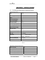
CUT 40 OWNER’S MANUAL Plasma Cutting Plasma Gouging Plasma Arc Cutting Power Source Machine Number: _________________________________ Where Purchase: _________________________________ Date of purchased: _________________________________ Table of Contents SECTION 1 SAFETY PRECAUTIONS ................................................................................... 1 SECTION 1 CONSIGNES DE SÉCURITÉ .................................................................................. 1 1-1. Symbol Usage ...................................................................................................... 1 Symboles utilisés .................................................................................................................. 1 1-2. Arc welding Hazards .......................................................................................... 1 Dangers relatifs au soudage à l’arc .................................................................................. 1 1-3. Safety Standards Normes de sécurité .................................................... 6 1-4. EMF Information EMF Information .............................................................. 6 SECTION 2 INSTALLATIONS .................................................................................................... 7 2-1. Cut 40 plasma cutting machine and gun specifications .......................... 7 2-2. Connection diagram ........................................................................................... 9 2-3. Install procedure ............................................................................................... 10 2-4. Electric service guide ...................................................................................... 11 SECTION 3 OPERATION ....................................................................................................... 12 3-1 Front/Back panel Layout ................................................................................. 12 3-2 Recommend Cutting parameter .................................................................... 15 SECTION 4 TROUBLE SHOOTING ..................................................................................... 16 5-1. Maintenance ....................................................................................................... 19 5-2. Safety precaution .............................................................................................. 20 SECTION 6 SECTION 7 SECTION 8 SECTION 9 ELECTRICAL DIAGRAM.................................................................................. 21 PARTS LIST ........................................................................................................ 23 WARRANTY POLICY ........................................................................................ 31 AUTHORIZED SERVICE CENTER ................................................................. 32 SECTION 1 SAFETY PRECAUTIONS SECTION 1 CONSIGNES DE SÉCURITÉ 1-1. Symbol Usage Symboles utilisés Means Warning! Watch Out! There are possible hazards with this procedure! The possible hazards are shown in the adjoining symbols. This group of symbols means Warning! Watch Out possible ELECTRIC SHOCK, MOVING PARTS, and HOT PARTS hazards. Consult symbols and related instructions below for necessary actions to avoid the hazards Symbole graphique d’avertissement ! Attention ! Cette procedure comporte des risques possibles ! Les dangers éventuels sont représentés par les symboles graphiques joints. Ce groupe de symboles signifie Avertissement! Attention! Risques d’ÉLECTROCUTION, ORGANES MOBILES et PARTIES CHAUDES. Consulter les symboles et les instructions afferents ci-dessous concernant les mesures à prendre pour supprimer les dangers. Marks a special safety message. Indique un message de sécurité particulier Means “Note”; not safety related. Signifie NOTE ; n’est pas relatif à la sécurité. 1-2. Arc welding Hazards Dangers relatifs au soudage à l’arc ELECTRIC SHOCK can kill. UNE DÉCHARGE ÉLECTRIQUE entraîner la mort. The symbols shown below are used throughout this manual to call attention to and identify possible hazards. When you see the symbol, watch out, and follow the related instructions to avoid the hazard. Only qualified persons should service, test, maintain, and re- pair this unit. y y During servicing, keep everybody, especially children, away y Les symboles représentés ci-dessous sont utilisés dans ce manuelpour attirer l’attention et identifier les dangers possibles. Enprésence de l’un de ces symboles, prendre garde et suivre lesinstructions afférentes pour éviter tout risque. Les instructions enmatière de sécurité indiquées ci-dessous ne constituent qu’un sommaire des instructions de sécurité plus complètes fournies dans les normes de sécurité énumérées dans la Section 2-5. Lire et observer toutes les normes de sécurité. Seul un personnel qualifié est autorisé à installer, faire fonctionner, entretenir et réparer cet appareil. Pendant le fonctionnement, maintenir à distance toutes les personnes, notamment les enfants de l’appareil. CUT40 OWNER’S MANUAL y y y y Do not touch live electrical parts. Wear dry, hole-free insulating gloves and body protection. Insulate yourself from work and ground using dry insulating mats or covers big enough to prevent any physical contact with the work or ground. Do not use AC output in damp areas, if movement is confined, or if there is a danger of falling. Use AC output ONLY if required for the welding process. If AC output is required, use remote output control if present on unit. Additional safety precautions are required when any of the following electrically hazardous conditions are present: in damp locations or while wearing wet clothing; on metal structures such as floors, gratings, or scaffolds; when in cramped positions such as sitting, kneeling, or lying; or when there is a high risk of unavoidable or accidental contact with the workpiece or ground. For these conditions, use the following equipment in order presented: 1) a semiautomatic DC constant voltage (wire) welder, 2) a DC manual (stick) welder, or 3) an AC welder with reduced open-circuit Manual no: WM070303 Page1 y y y y y y y y y y y y y y y y y voltage. In most situations, use of a DC, constant voltage wire welder is recommended. And, do not work alone! Disconnect input power or stop engine before installing or servicing this equipment. Lockout/tagout input power according to OSHA 29 CFR 1910.147 (see Safety Standards). Properly install and ground this equipment according to its Owner’s Manual and national, state, and local codes. Always verify the supply ground − check and be sure that input power cord ground wire is properly connected to ground terminal in disconnect box or that cord plug is connected to a properly grounded receptacle outlet. When making input connections, attach proper grounding conductor first − double-check connections. Frequently inspect input power cord for damage or bare wiring − replace cord immediately if damaged − bare wiring can kill. Turn off all equipment when not in use. Do not use worn, damaged, undersized, or poorly spliced cables. Do not drape cables over your body. If earth grounding of the workpiece is required, ground it directly with a separate cable. Do not touch electrode if you are in contact with the work, ground, or another electrode from a different machine. Do not touch electrode holders connected to two welding machines at the same time since double open-circuit voltage will be present. Use only well-maintained equipment. Repair or replace damaged parts at once. Maintain unit according to manual. Wear a safety harness if working above floor level. Keep all panels and covers securely in place. Clamp work cable with good metal-to-metal contact to workpiece or worktable as near the weld as practical. Insulate work clamp when not connected to workpiece to prevent contact with any metal object. Do not connect more than one electrode or work cable to any single weld output terminal. SIGNIFICANT DC VOLTAGE exists after removal of input power on inverters. y y y y y y y y y y y y y y Turn Off inverter, disconnect input power, and discharge input capacitors according to instructions in Maintenance Section before touching any parts. y Ne pas toucher aux pièces électriques sous tension. Porter des gants isolants et des vêtements de protection secs et sans trous. S’isoler de la pièce à couper et du sol en y CUT40 OWNER’S MANUAL y y y utilisant des housses ou des tapis assez grands afin d’éviter tout contact physique avec la pièce à couper ou le sol. Ne pas se servir de source électrique à courant électrique dans les zones humides, dans les endroits confinés ou là où on risque de tomber. Se servir d’une source électrique à courant électrique UNIQUEMENT si le procédé de soudage le demande. Si l’utilisation d’une source électrique à courant électrique s’avère nécessaire, se servir de la fonction de télécommande si l’appareil en est équipé. D’autres consignes de sécurité sont nécessaires dans les conditions suivantes : risques électriques dans un environnement humide ou si l’on porte des vêtements mouillés ; sur des structures métalliques telles que sols, grilles ou échafaudages ; en position coincée comme assise, à genoux ou couchée ; ou s’il y a un risque élevé de contact inévitable ou accidentel avec la pièce à souder ou le sol. Dans ces conditions, utiliser les équipements suivants, dans l’ordre indiqué : 1) un poste à souder DC à tension constante (à fil), 2) un poste à souder DC manuel (électrode) ou 3) un poste à souder AC à tension à vide réduite. Dans la plupart des situations, l’utilisation d’un poste à souder DC à fil à tension constante est recommandée. En outre, ne pas travailler seul ! Couper l’alimentation ou arrêter le moteur avant de procéder à l’installation, à la réparation ou à l’entretien de l’appareil. Déverrouiller l’alimentation selon la norme OSHA 29 CFR 1910.147 (voir normes de sécurité). Installer le poste correctement et le mettre à la terre convenablement selon les consignes du manuel de l’opérateur et les normes nationales, provinciales et locales. Toujours vérifier la terre du cordon d’alimentation. Vérifier et s’assurer que le fil de terre du cordon d’alimentation est bien raccordé à la borne de terre du sectionneur ou que la fiche du cordon est raccordée à une prise correctement mise à la terre. En effectuant les raccordements d’entrée, fixer d’abord le conducteur de mise à la terre approprié et contre-vérifier les connexions. Vérifier fréquemment le cordon d’alimentation afin de s’assurer qu’il n’est pas altéré ou à nu, le remplacer immédiatement s’il l’est. Un fil à nu peut entraîner la mort. L’équipement doit être hors tension lorsqu’il n’est pas utilisé. Ne pas utiliser des câbles usés, endommagés, de grosseur insuffisante ou mal épissés. Ne pas enrouler les câbles autour du corps. Si la pièce soudée doit être mise à la terre, le faire directement avec un câble distinct. Ne pas toucher l’électrode quand on est en contact avec la pièce, la terre ou une électrode provenant d’une autre machine. Ne pas toucher des porte électrodes connectés à deux machines en même Manual no: WM070303 Page2 temps à cause de la présence d’une tension à vide doublée. N’utiliser qu’un matériel en bon état. Réparer ou remplacer sur-lechamp les pièces endommagées. Entretenir l’appareil conformément à ce manuel. Porter un harnais de sécurité si l’on doit travailler au-dessus du sol. S’assurer que tous les panneaux et couvercles sont correctement en place. Fixer le câble de retour de façon à obtenir un bon contact métal-métal avec la pièce à souder ou la table de travail, le plus près possible de la soudure. Isoler la pince de masse quand pas mis à la pièce pour éviter le contact avec tout objet métallique. Ne pas raccorder plus d’une électrode ou plus d’un câble de masse à une même borne de sortie de soudage. y y y y y y y Ne pas surcharger l’installation électrique − s’assurer que l’alimentation est correctement dimensionnée et protégée avant de mettre l’appareil en service. FLYING METAL can injure eyes. DES PARTICULES VOLANTES peuvent blesser les yeux. y y y Il reste une TENSION DC NON NÉGLIGEABLE dans les sources de soudage onduleur quand on a coupe l’alimentation. y Arrêter les convertisseurs, débrancher le courant électrique et décharger les condensateurs d’alimentation selon les instructions indiquées dans la partie Entretien avant de toucher les pièces. y y y y y Do not touches hot parts bare handed. y Allow cooling period before working on welding gun or torch y Ne pas toucher des parties chaudes à mains nues. y Prévoir une période de refroidissement avant d’utiliser le pistolet ou la torche. Put on grounded wrist strap BEFORE handling boards or parts. Use proper static-proof bags and boxes to store, move, or ship PC boards. Établir la connexion avec la arrette de terre avant de manipuler des cartes ou des pièces. Utiliser des pochettes et des boîtes antistatiques pour stocker, déplacer ou expédier des cartes PC. MAGNETIC FIELDS can affect pacemakers. LES CHAMPS MAGNÉTIQUES peuvent affecter les stimulateurs cardiaques. FIRE OR EXPLOSION hazard. Risque D’INCENDIE OU D’EXPLOSION. y y y Do not place unit on, over, or near combustible surfaces. Do not service unit near flammables Do not overload building wiring − be sure power supply system is properly sized, rated, and protected to handle this unit. Le soudage, l’écaillement, le passage de la pièce à la brosse en fil de fer, et le meulage génèrent des étincelles et des particules métalliques volantes. Pendant la période de refroidissement des soudures, elles risquent de projeter du laitier. Porter des lunettes de sécurité avec écrans latéraux ou un écran facial. HOT PARTS can cause severe burns. DES PIÈCES CHAUDES peuvent provoquer des brûlures graves. STATIC (ESD) can damage PC boards. LES CHARGES ÉLECTROSTATIQUES peuvent endommager les circuits imprimés. y Wear safety glasses with side shields or face shield during servicing. Be careful not to short metal tools, parts, or wires together during testing and servicing. y y Pacemaker wearers keep away. Wearers should consult their doctor before going near arc welding, gouging, or spot welding operations. y Porteurs de stimulateur cardiaque, rester à distance. Les porteurs d’un stimulateur cardiaque doivent d’abord consulter leur médecin avant de s’approcher des opérations de soudage à l’arc, de gougeage ou de soudage par points. y Ne pas placer l’appareil sur, au-dessus ou à proximité de surfaces inflammables. y Ne pas installer l’appareil à proximité de produits inflammables. y CUT40 OWNER’S MANUAL Manual no: WM070303 Page3 CYLINDERS can explode if damaged. LES BOUTEILLES peuvent exploser si elles sont endommagées. Shielding gas cylinders contain gas under high pressure. If damaged, a cylinder can explode. Since gas cylinders are normally part of the welding process, be sure to treat them carefully. y Protect compressed gas cylinders from excessive heat, mechanical shocks, physical damage, slag, open flames, sparks, and arcs. y Install cylinders in an upright position by securing to a stationary support or cylinder rack to prevent falling or tipping. y Keep cylinders away from any welding or other electrical circuits. y Never drape a welding torch over a gas cylinder. y Never allow a welding electrode to touch any cylinder. y Never weld on a pressurized cylinder − explosion will result. y Use only correct shielding gas cylinders, regulators, hoses, and fittings designed for the specific application; maintain them and associated parts in good condition. y Turn face away from valve outlet when opening cylinder valve. y Keep protective cap in place over valve except when cylinder is in use or connected for use. y Use the right equipment, correct procedures, and sufficient number of persons to lift and move cylinders. y Read and follow instructions on compressed gas cylinders, associated equipment, and Compressed Gas Association (CGA) publication P-1 listed in Safety Standards. Des bouteilles de gaz protecteur contiennent du gaz sous haute pression. Si une bouteille est endommagée, elle peut exploser. Du fait que les bouteilles de gaz font normalement artie du procédé de soudage, les manipuler avec précaution. y Protéger les bouteilles de gaz comprimé d’une chaleur excessive, des chocs mécaniques, des dommages physiques, du laitier, des flammes ouvertes, des étincelles et des arcs. y Placer les bouteilles debout en les fixant dans un support stationnaire ou dans un porte-bouteilles pour les empêcher de tomber ou de se renverser. y Tenir les bouteilles éloignées des circuits de soudage ou autres circuits électriques. y Ne jamais placer une torche de soudage sur une bouteille à gaz. y Une électrode de soudage ne doit jamais entrer en contact avec une bouteille. y Ne jamais souder une bouteille pressurisée − risque d’explosion. y Utiliser seulement des bouteilles de gaz protecteur, régulateurs, tuyaux et raccords convenables pour cette application spécifique ; les maintenir ainsi que les éléments associés en bon état. y Détourner votre visage du détendeur-régulateur lorsque vous ouvrez la CUT40 OWNER’S MANUAL soupape de la bouteille. y Le couvercle du détendeur doit toujours être en place, sauf lorsque la bouteille est utilisée ou qu’elle est reliée pour usage ultérieur. y Utiliser les équipements corrects, les bonnes procédures et suffisamment de personnes pour soulever et déplacer les bouteilles. y Lire et suivre les instructions sur les bouteilles de gaz comprimé, l’équipement connexe et le dépliant P-1 de la CGA (Compressed Gas Association) mentionné dans les principales normes de sécurité. FALLING UNIT cause injury. LA CHUTE L’APPAREIL blesser. y y y y y y can DE peut Use lifting eye to lift unit only, NOT running gear, gas cylinders, or any other accessories. Use equipment of adequate capacity to lift and support unit. If using lift forks to move unit, be sure forks are long enough to extend beyond opposite side of unit Utiliser l’anneau de levage uniquement pour soulever l’appareil, NON PAS les chariots, les bouteilles de gaz ou tout autre accessoire. Utiliser un équipement de levage de capacité suffisante pour lever l’appareil. En utilisant des fourches de levage pour déplacer l’unité, s’assurer que les fourches sont suffisamment longues pour dépasser du côté opposé de l’appareil. MOVING PARTS can cause injury. DES ORGANES MOBILES peuvent provoquer des blessures. y y y y y y y y Keep away from moving parts such as fans. Keep all doors, panels, covers, and guards closed and securely in place. Have only qualified persons remove doors, panels, covers, or guards for maintenance as necessary. Reinstall doors, panels, covers, or guards when maintenance is finished and before reconnecting input power. S’abstenir de toucher des organes mobiles tells que des ventilateurs. Maintenir fermés et verrouillés les portes, panneaux, recouvrements et dispositifs de protection. Seules des personnes qualifiées sont autorisées à enlever les portes, panneaux, recouvrements ou dispositifs de protection pour l’entretien. Remettre les portes, panneaux, recouvrements ou dispositifs de protection quand l’entretien est terminé et avant de rebrancher l’alimentation électrique. Manual no: WM070303 Page4 MOVING PARTS can cause injury. DES ORGANES MOBILES peuvent provoquer des blessures. y y Keep away from moving parts Keep away from pinch points such as drive rolls y y Ne pas s’approcher des organes mobiles. Ne pas s’approcher des points de coincement tels que des rouleaux de commande. OVER USE can cause OVERHEATING. L’EMPLOI EXCESSIF peut SURCHAUFFER L’ÉQUIPEMENT. Allow cooling period; follow rated duty cycle. Reduce current or reduce duty cycle before starting to weld again. Do not block or filter airflow to unit interference problem resulting from the installation. If notified by the FCC about interference, stop using the equipment at once. Have the installation regularly checked and maintained. Keep high-frequency source doors and panels tightly shut, keep spark gaps at correct setting, and use grounding and shielding to minimize the possibility of interference. y y y Le rayonnement haute fréquence (HF) peut provoquer des interférences avec les équipements de radio-navigation et de communication, les services de sécurité et les ordinateurs. Demander seulement à des personnes qualifiées familiarisées avec des équipements électroniques de faire fonctionner l’installation. L’utilisateur est tenu de faire corriger rapidement par un electrician qualifié les interférences résultant de l’installation. Si le FCC signale des interférences, arrêter immédiatement l’appareil. Effectuer régulièrement le contrôle et l’entretien de l’installation. y y y y y y Prévoir une période de refroidissement ; respecter le cycle opératoire nominal. Réduire le courant ou le facteur de marche avant de poursuivre le soudage. Ne pas obstruer les passages d’air du poste. H.F. RADIATION can cause interference. LE SOUDAGE À L’ARC risque de provoquer des interférences. y y y High-frequency (H.F.) can interfere with radio navigation, safety services, computers, and communications equipment. Have only qualified persons familiar with electronic equipment perform this installation. The user is responsible for having a qualified electrician promptly correct any CUT40 OWNER’S MANUAL Maintenir soigneusement fermés les portes et les panneaux des sources de haute fréquence, maintenir les éclateurs à une distance correcte et utiliser une terre et un blindage pour réduire les interférences éventuelles. READ INSTRUCTIONS. LIRE LES INSTRUCTIONS. Consult the Owner’s Manual for welding safety precautions. Use only genuine replacement parts Lire le manuel d’utilisation avant d’utiliser ou d’intervenir sur l’appareil. Utiliser uniquement des pièces de rechange. Manual no: WM070303 Page5 1-3. Safety Standards Normes de sécurité Safety in Welding, Cutting, and Allied Processes, ANSI Standard Z49.1, from Global Engineering Documents (phone: 1-877-413-5184, website: www.global.ihs.com). Code for Safety in Welding and Cutting, CSA Standard W117.2, from Canadian Standards Association, Standards Sales, 178 Rexdale Boulevard, Rexdale, Ontario, Canada M9W 1R3 (phone: 800−463−6727 or in Toronto 416−747−4044, website: www.csa−international.org). Safety in Welding, Cutting, and Allied Processes, ANSI Standard Z49.1, de Global Engineering Documents (téléphone : 1-877-413-5184, site Internet : www.global.ihs.com). Code for Safety in Welding and Cutting, CSA Standard W117.2, de Canadian Standards Association, Standards Sales, 178 Rexdale Boulevard, Rexdale, Ontario, Canada M9W 1R3 (téléphone : 800-463-6727 ou à Toronto 416-747-4044, site Internet : www.csa-international.org). 1-4. EMF Information EMF Information Considerations About Welding And The Effects Of Low Frequency Electric And Magnetic Fields 1. Keep cables close together by twisting or taping them. Welding current, as it flows through welding cables, will cause electro- magnetic fields. There has been and still is some concern about such fields. However, after examining more than 500 studies spanning 17 years of research, a special blue ribbon committee of the National Research Council concluded that: “The body of evidence, in the committee’s judgment, has not demonstrated that exposure to power- frequency electric and magnetic fields is a human-health hazard.” However, studies are still going forth and evidence continues to be examined. Until the final conclusions of the research are reached, you may wish to minimize your exposure to electromagnetic fields when welding or cutting. 2. Arrange cables to one side and away from the operator. To reduce magnetic fields in the workplace, use the following procedures: Considérations sur le soudage et les effets de basse fréquence et des champs magnétiques et électriques. Le courant de soudage, pendant son passage dans les câbles de soudage, causera des champs électromagnétiques. Il y a eu et il y a encore un certain souci à propos de tels champs. Cependant, après avoir examine plus de 500 études qui ont été faites pendant une période de recherché de 17 ans, un comité spécial ruban bleu du National Research Council a conclu : « L’accumulation de preuves, suivant le jugement du comité, n’a pas démontré que l’exposition aux champs magnétiques et champs électriques à haute fréquence représente un risque à la santé humaine ». Toutefois, des études sont toujours en cours et les preuves continuent à être examinées. En attendant que les conclusions finales de la recherché soient établies, il vous serait souhaitable de réduire votre exposition aux champs électromagnétiques pendant le soudage ou le coupage. 3. Do not coil or drape cables around your body. 4. Keep welding power source and cables as far away from operator as practical. 5. Connect work clamp to work piece as close to the weld as possible. About Pacemakers: Pacemaker wearers consult your doctor first. If cleared by your doctor, then following the above procedures is recommended en les enveloppant. 2. Disposer les câbles d’un côté et à distance de l’opérateur. 3. Ne pas courber pas et ne pas entourer pas les câbles autour de votre corps. 4. Garder le poste de soudage et les câbles le plus loin possible de vous. 5. Connecter la pince sur la pièce aussi près que possible de la soudure. En ce qui concer ne les sti mulateurs cardiaques Les porteurs de stimulateur cardiaque doivent consulter leur médecin avant de souder ou d’approcher des opérations de soudage. Si le médecin approuve, il est recommandé de suivre les procédures precedents Pour réduire les champs magnétiques sur le poste de travail, appliquer les procédures suivantes : 1. Maintenir les câbles ensemble en les tordant ou CUT40 OWNER’S MANUAL Manual no: WM070303 Page6 SECTION 2 INSTALLATIONS 2-1. Cut 40 plasma cutting machine and gun specifications CUT 40 Cutting machine Type CUT40 Power supply 208/230V/60Hz Phase 1 Rated input power(Kva) 4.5 Open circuit voltage(v) 300 Amperage range(A) 25-40 Rated working voltage(V) 90-96 Rated Duty cycle (%) 60 Rated working current(A) 40 Gas Delay time(s) 0-15 Compress air Pressure(psi) 35.6-64(0.25-0.45MPA) Gas Type Air or Nitrogen Gas Quality Air: Clean, dry, oil free Nitrogen: 99.995% pure Dimension(HxWxD)(CM) 52×26×49 Weight(KG) 25 Table 2.1 CB50 Plasma cutting gun Specifications Rated currency(A) 50 Rated Duty cycle (%) 60% at 50A, 100% at 40A Cool style Air cooled Maximum Air pressure(Bar) 5 (5 kg/cm2) Air comsumption(l/min) 165 CUT40 OWNER’S MANUAL Manual no: WM070303 Page7 Cable length(M) 6 Connection Centre connection Detailed gun specification please see separate gun manual Table 2.2 CAUTION WORKING LONGER THAN RATED DUTY CYCLE CAN DAMAGE GUN AND VOID WARRANTY. CUT40 OWNER’S MANUAL Manual no: WM070303 Page8 2-2. Connection diagram Connect to air supply Cutting gun Power cord Earth clamp, connect to work piece Figure 2.1 CUT40 OWNER’S MANUAL Manual no: WM070303 Page9 2-3. Install procedure 2-3.1. Welding machine should be installed in a stable position and with good ventilation. Avoid direct sun outdoors. Avoid transport in invert or side position. Figure 2.2 Connect Plasma torch 2-3.2. Connect CB50 plasma gun. Attach the male connector (torch side) to the female one (machine side). Make sure that the positioning pin aligns with the corresponding notch, then use enclosed tool (D) to disengage the anti-rotation device by pressing it on proper hole (C). To disconnect torch also need press enclosed tool to the hole. Finally, remove the tool and continue to fasten the ring until hear clicking. 2-3.3. Connect machine with 208/230V single phase power supplies. CAUTION SHOCK HAZARD: ALWAYS TURN OFF THE POWER, UNPLUG THE CORD AND WAIT 5 MINUTES BEFORE REMOVE AND POWER SUPPLY COVER. IF THE POWER SUPPLY IS DIRECTLY CONNECTED TO A LINE DISCONNECTION, PLACE SWITCH IN THE OFF POSITION. IN THE US, USE A “LOCK-OUT/TAG-OUT” PROCEDURE UNTIL THE SERVICE OR MAINTENANCE WORK IS COMPLETE. IN THE OTHER COUNTRIES, FOLLOW APPROPRIATE LOCAL OR NATIONAL SAFETY PROCEDURE. 2-3.4. Be sure machine is well grounded. 2-3.5. Connect torch, earth cable, wire, regulator, cylinder according to connection diagram. Refer to torch’s manual for the torch lead connection. 2-3.6. Gas supply can be either air or Nitrogen. A high pressure regulator must be used on either type of gas and must be capable of delivering 155 l/min at a pressure of 5 kg/cm2 (4.9 bars) to the filter. 2-3.7. Use a 3/8 inch (9.5mm) ID inert gas hose to connect the gas supply (air or nitrogen) to the power supply filter. To connect the hose, install a 1/4 NPT nipple to the filer as show in Figure 2.1. Apply liquid pipe sealant to the threads to ensure a leak-free installation. Never use Teflon tape when installing the nipple or adapters. Bits of tape can break off and enter the air line and harm the pressure regulator, pressure switch and valve. 2-3.8. Use a three-stage coalescing filtration system as shown in Fig 2.2 when site conditions introduce moisture, oil or other contaminants into the air line. CUT40 OWNER’S MANUAL Manual no: WM070303 Page10 Water/particle filter oil filter oil vapour filter From air Supply Figure 2.2 Three stage coalescing filtration system 2-4. Electric service guide CAUTION WARNING: THIS WELDING MACHINE MUST BE CONNECTED TO POWER SOURCE IN ACCORDANCE WITH APPLICABLE ELECTRICAL CODES AVERTISSEMENT: LE RACCORDEMENT DE CETTE MACHINE DE SOUDAGE Á L’ALIMENTATION DOIT ÉTRE CONFORME AUX CODES D’ ÉLECTRICITÉ PERTINENTS Input voltage(V) 208 230 Frequency(Hz) 60 Input Amperes at rated output(A) 30 28 Circuit breaker, time delay 35 35 Normal operation 45 45 Min input conductor size in AWG 10 10 Max Recommended input conductor Length(M) 23 31 Min Grounding conductor Size in AWG 10 10 Max recommended standard fuse Rating in Amperes Table 2.1 CUT40 OWNER’S MANUAL Manual no: WM070303 Page11 SECTION 3 OPERATION C AUTION BEFORE OPERATING THIS MACHINE, READ THE SAFETY SECTION OF THIS MANUAL THOROUGHLY 3-1 Front/Back panel Layout 1 2 4 3 5 Figure 3.1 CUT40 OWNER’S MANUAL Manual no: WM070303 Page12 6 10 7 8 11 9 Figure 3.2 1. Current meter(digital) 2. Power indicator 3. Over-heat protection indicator 4. Work indicator 5. welding current adjust knob 6. Fuse CUT40 OWNER’S MANUAL 7. Input Power cord Compress air inlet 8. Power switch 9. Fan 10. Air filter 11. Gas Inlet Manual no: WM070303 Page13 3-1.1 Check the connection of work piece, earth cable, welding torch, gas cylinder, regulator and hose, make sure they are firm and reliable. Do not attach earth cable to the portion that will fall away. Figure 3.2 Correct way to attach earth clamp Figure 3.3 3-1.2 Verify that the input gas supply pressure is set to 5kg /cm2 (5 Bar). 3-1.3 Pull the regulator cap out, gradually turn regulator cap to adjust gas pressure to 3.5-4.5 kg/cm2 (3.5-4.5 Bar) and push the regulator cap back in. 3-1.4 Switch on the power source. The power light (red) should illuminate. Adjust the cutting current and after cutting delay time knob to desired setting. 3-1.5 Place the tip of the torch at the edge of the work piece makes sure the tip is vertical to the work piece. When piercing, the tip should have a angle away from yourself, after arc starts, slowly rotate the torch to upright position. This is to blow the melted metal away and is particularly important when cutting thicker material. Make sure that the torch is pointed away from you and the people near you to avoid any danger from sparks and hot metal. Push the safety trigger at the side of the torch first, then press the switch to start cutting. C AUTION CUT-40 CUTTING MACHINES ARE CONTACT-START, THE PLASMA ARC IGNITED IMMEDIATELY AFTER START SWITCH CLOSED. ALWAYS HOLD THE HAND TORCH AWAY FROM YOUR BODY AS A PRECAUTION AGAINST ACCIDENTAL TORCH FIRING. BE AWARE OF THIS HAZARD. FAILURE TO DO SO CAN RESULT IN SERIOUS BODILY INJURY. 3-1.6 After arc starts, hold the torch nozzle at vertical position and watch the arc as it cut along the line. By lightly dragging the shield on the workpiece, you can maintain a steady cut. For straight-line cutting, use any straight edge as a guide. 3-1.7 Evenly move the torch in the desired direction, at a speed which will ensure good cut quality. Pulling the torch through the cut is easier than push it. 3-1.8 When cutting, make sure that the sparks are coming out of the bottom of the metal. If they are spraying on top of the workpiece, you are moving the torch too fast, or you do not have sufficient power to fully penetrate the workpiece. 3-1.9 When the cut is finished, release the torch switch to extinguish the arc. 3-1.10 After finish operation, turn off the gas valve. In the end, turn off welding power source and wall switch. CUT40 OWNER’S MANUAL Manual no: WM070303 Page14 3-2 Recommend Cutting parameter The settings listed below are just for initial commission of the machine. The parameters can be refined in actual cutting. Material Mild steel Aluminum Stainless steel Thickness (inches) (mm) Current (amps) 26 GA 0.5 20 270 6850 16 GA 1.5 40 400 10150 1 /8 3.2 40 190 4950 1 /4 6.4 40 65 1680 3 /8 10 40 25 640 5 /8 16 40 9 250 0.020 1 20 160 4150 16GA 1.5 40 430 10900 1 /8 3.2 40 170 4450 1 /4 6.4 40 60 1620 3 /8 10 40 20 510 5 /8 16 40 8 200 26 GA. 0.5 20 230 5970 16 GA. 1.5 40 400 10150 1 /8 3.2 40 160 4060 1 /4 6.4 40 50 1320 3 /8 10 40 20 510 5 /8 16 40 7 180 (ipm) Maximum travel speed (mm/min.) Table 3.1 CUT40 OWNER’S MANUAL Manual no: WM070303 Page15 SECTION 4 TROUBLE SHOOTING No. Problem Cause Solution 1 Power Indication lamp is not illuminate after Loose contact at input lead Check contact situation Lamp malfunction, poor Check contact situation. contact Replace lamp Main switch malfunction Check switch, replace if switch on the main switch necessary 2 Electric leak at the case Power cord leak Insulate power cord Transformer contact with Insulate transformer case 3 Power Indication lamp is on, but arc does not extinguish after release the torch switch Not grounding properly Check and redo the grounding The switch shortcut Replace switch The switch contact Re-insulate terminal terminal shortcut 4 Cooling fan stops to Power indication Cooling fan circuit rotate after machine lamp on malfunction has worked a Check fan circuit Cool fan failure period Power indication Check fan, replace if necessary See No. 1 lamp off 5 6 Machine does not response after push the Trigger shortcut or control start trigger cable broken Replace/re-connect Control transformer failure Replace There are high frequency but arc fail to The torch cable open Re-connect ignite or does not ignite properly circuit Control circuit board failure Check and repair the circiut board The HF spark gap too CUT40 OWNER’S MANUAL Manual no: WM070303 Adjust gap to 2 mm Page16 narrow Poor contact at earth lead Check and re-connect and gun cable Loose or poor connection Check the connetion with the main power supply link Water in the air Drain water or Change filter compressor or filter 7 Work piece thickness Poor penetration during cutting Use higher capacity cutter excess the capacity of the machine Cutting speed is too fast Slow down Torch tilt to much Adjust angle to verical Air pressure is too low or Adjust the pressure too high 8 The arc extinguish suddenly during welding Consumables are worn Change consumables Line voltage is too low Use Voltage stabilizer The cutting speed is too Adjust the speed slow Electrode too far away Reduce the torch or put torch from work piece surface on the workpiece The Nozzle or electrode Replace are faulty 9 Power supply switch jump Control transformer short Check and replace circuit Solenoid valve short circuit Check and replace Cooling fan short circuit Check and replace Work excess the rated Use under rated duty circle duty circle CUT40 OWNER’S MANUAL Manual no: WM070303 Page17 Input voltage is too high 10 Use proper voltage The power light illuminated, the Overheat One of the internal Leave Power supply on to allow light stay illuminated and the torch will not thermostat switches has the fan to cool the machine. fire opened due to over Then shut the power supply heating down and restart. Clean the internal air filter. 11 Torch sputters and hisses The gas filter at the rear of Drain the filter bowl and clean the machine contains the filter. See MAINTENANCE excessive moisture SECTION. Table 4.2 If you are unable to fix the problem with your plasma cutting machine by following this basic troubleshooting guide or if you need further assistance: 1. Call your distributor. He will be able to help you, or refer you to an authorized repair facility. 2. Call the company office, which listed in the back of this manual. CUT40 OWNER’S MANUAL Manual no: WM070303 Page18 SECTION 5 MAINTENANCE 5-1. Maintenance Periodic maintenance is necessary for keeping the machine work properly. CAUTION DISCONNECT POWER INPUT AND SWITCH OFF THE MAIN POWER SWITCH BEFORE START OF MAINTENANCE. Cap Filter element Pressure meter Gas supply hose Filter Bowl Figure 5.1 Regular Check and Inspection Bowl Draining and Filter Element Cleaning • Check and change broken electrode and nozzle to avoid damage to the torch and machine. Moisture in the torch can cause the torch to sputter and hiss. If moisture is present, purge the gas lines. If moisture builds up in the bowl of the filter, drain the bowl and clean the filter element: • Check the function of all switches. • Check if the fan rotates properly and if there is air venting out from back of the machine • Pay Attention to the abnormal vibration, noise, smell and gas leakage during operation • Check if the cutting cables are over heated? • Check if the cable connections are over heated? • Shut off the gas supply and disconnect the gas supply hose from the filter assembly before proceeding. • Remove the cap at the bottom of the filter bowl and turn the knurled drain valve to the right to release water from the bowl. • Unscrew the filter bowl. • Unscrew the filter element. • Check If the cable is connected firmly and properly, if it is broken and cause bad insulation? • Clean the filter element with alcohol, and then blow it out with air. Clean the bowl with household soap only. • Check the cover grounded properly • Replace the filter element and filter bowl. • Reconnect the gas supply hose. Table 5.1 CUT40 OWNER’S MANUAL Manual no: WM070303 Page19 5-2. Safety precaution 5-2.1. Operator must be equipped with mask, gloves and tie the sleeves and collar properly. There should be an arc shield around welding field to protect others from arc shock. 5-2.2. Do not weld near flammable, explosive materials or gases. 5-2.3. Gas cylinder must be located at a safe and steady place to avoid injury others. 5-2.4. Keep finger, hair and clothing away from the rotating fan. 5-2.5. The power source must be grounded when welding. 5-2.6. Welding machine should not work in a flammable and toxic environment, avoid moisture, rain, and do not directly expose to sun. 5-2.7. Periodically maintain the machine and clean the dust inside. CUT40 OWNER’S MANUAL Manual no: WM070303 Page20 SECTION 6 ELECTRICAL DIAGRAM + 114 - 115 Air Swich A BR1 SK1 B C O Fan 18V/1A 101 18V/1A 102 18V/1A 103 220 0 380 415 Transformer 15V/1A 113 15V/1A 112 10V/0.3A 111 10V/0.3A 110 110V/1A 109 107 36V/3A 108 0V 18V/0.5A 106 18V/0.5A 105 18V/0.5A 104 3A 3A11 3A12 4A13 1A7 2 1 1 2 3 1A8 1A CURRENT METER 138 137 1A11 6 1 5 2 140 4 3139 115 114 102 103 101 111 110 2 1 1 2 3 4 5 6 7 8 9 3 2 1 5 4 3 2 1 1 2 3 REMOTE 1A10 POWER 104 105 106 116 5 4 3 2 1 1A2 1A3 1A4 118 116 Thermostat CUTTING CURRENT Figure 6.1 CUT40 OWNER’S MANUAL Manual no: WM070303 Page21 124 123 122 121 120 119 118 117 117 4 3 2 1 4 3 2 1 1 2 3 2 1 O.C 1A6 + 134 133 O 132 G 131 138 T1 125 126 2.2K PILOT ARC 137 G O + INDUCTOR 130 129 128 127 4A4 2A5 5A1 4 3 2 1 4A 4A3 109 118 119 120 121 1 2 2 1 1 2 131 3 132 4 133 5 134 2 126 1 125 1 2 3 4 4A7 107 108 1 2 3 4 50W/150 4A6 1 2 3 117 2A 2A4 1 2 Gas pressure switch 5 4 3 2 1 136 2A7 107 108 1 2 3 4 5 2A3 Solenoid valve 107 gas check 2A6 I 4 3 2 1 104 O cutting 2A1 2A5 2A2 1 2 3 4 3 2 1 1 2 3 107 108 work 135 4T Solenoid valve 116 I 112 O 140 139 torch switch 2T Figure 6.2 CUT40 OWNER’S MANUAL Manual no: WM070303 Page22 SECTION 7 1 2 7 PARTS LIST 9 8 16 15 6 10 11 4 3 5 12 14 Figure 7.1 CUT40 OWNER’S MANUAL Manual no: WM070303 Page23 13 17 28 18 19 27 20 26 21 22 23 25 24 Figure 7.2 CUT40 OWNER’S MANUAL Manual no: WM070303 Page24 29 30 11 45 44 43 31 42 32 41 33 40 36 34 35 37 38 Figure 7.3 CUT40 OWNER’S MANUAL Manual no: WM070303 Page25 39 Item Order No. Description Note Quantity 1 Y09020016 Digital meter XL5135(AC9/DC)V-3 1 2 Y04060004 LED Indication light(red) ф5/RED 1 3 Y16010563 CUT-40 Front Panel JKJ-C258-A0(AH2351) 1 4 Y07060010 Centre torch connector FY-0022 1 5 Y07060004 Quick Connector 35-70cm 1 6 Y01430007 Cutting current Knob RN 110Z Red and black 1 Y01430007 Cutting current adjust potentiometer WH118/4.7K/2W 1 7 Y04060006 LED Indication light(yellow) Φ5/ Yellow 1 8 Y04060005 LED Indication light(green) Φ5/ Green 1 9 Y18020007 FUSE holder 6*30 1 10 Y25050301 Power cord PG-21 1 11 Y08030003 Air circuit breaker power switch DE47-60A/2P 1 12 Y22010003 FAN 12038 DC24V/0.31A 1 13 Y26100009 Air connector Imperial thread 1 14 Y16020278 BACK PANNEL 1 15 Y21060001 Air Filter and Gauge JKJ-C257-A1(AH2351)( SY-C2082-A0) AFR-2000 1 16 Y26050164 Protection case WJJ-C055-A0(AH2351) 1 17 Y27010107 Control transformer INV.LG-KB-01-A2 1 18 Y16050103 Middle separation plate HCP-60 JKJ-C235-A2 1 19 Y23010157 Heat sink HCP-60 SRQ-C054-A1 1 20 Y04040006 Diode module DWM90*2-06N 2 21 B03010113 inductance INV.NB-350-A1 1 22 Y08080027 Air pressure relay LF3kgf/cm^20 1 23 Y21010030 Solenoid valve ZCT-2.5-AC36V 1 24 B01022008 Capacitor PCB CUT-XS-A2 1 25 Y10020006 Hall sensor BLY2-50IOV2L 2 26 B01032001 Rectifier PCB JLBH-A1 1 27 B01073002 HF PCB 2009-02-12 1 28 B01062010 Drive PCB LG-WH-A0 1 29 B01042022 Control PCB HCP-60 1 30 B01062004 Drive PCB NB-350JZ-QD 1 31 Y01181500 Concrete resistance 50W-150R 1 32 Y02010075 CBB Capacitor MKPH-R-5uF/1200V 1 33 B03020028 Ignition coil INV.CUT-40-YH-A0 1 34 B03040063 Main transformer INV.CUT-40-ZB-A0 1 35 Y02010017 CBB Capacitor 106/1250V 2 36 B03010138 Reactor INV.HCP-60-DG-A0 1 37 Y04070021 Rectifier bridge MDQ-50A/1200V 1 38 Y02060064 Capacitor 2200uF/400V 1 CUT40 OWNER’S MANUAL Manual no: WM070303 Page26 39 Y02010083 Capacitor MFD-01-100uF/800VDC 1 40 Y05040026 IGBT Module BSM75GB60DLC 2 41 Y02010091 Capacitor 1 42 B02030265 Bar connector MKPH-SO(2*0.027uF/D C1200V LJJ-C065-A0 2 43 B01082017 Coupling PCB IGBT-OH-A0 1 44 Y23010158 Radiator SRQ-C055-A1 1 45 Y27010119 Control transformer INV.LG-KB-02-A2 1 Table 7.1 CUT40 OWNER’S MANUAL Manual no: WM070303 Page27 Figure 7.4 CUT40 OWNER’S MANUAL Manual no: WM070303 Page28 CB50 Plasma torch consumable list: Item Description Order No. 1 Nozzle outside CB50. 07PC0003 2 Electrode CB50. 07PR0016 3 TIP 1.0MM CB50 07PD0015-10 4 Swirl ring CB50 07PE0007 Table 7.2 CUT40 OWNER’S MANUAL Manual no: WM070303 Page29 NOTES WELDKING™ CUT40 CUT40 OWNER’S MANUAL Manual no: WM070303 Page30 SECTION 8 WARRANTY POLICY Malo Welding Products Ltd., Warranty Policy Effective August 1st, 2004, revision at April 1st, 2011 LIMITED WARRANTY - Subject to the terms and conditions below, Malo Welding Products Ltd.(WELDKING™ ) endeavors to provide high quality products and product support to its customers and therefore backs up all of its new products purchased from Malo Welding Products Ltd.(WELDKING™ ) or any authorized Malo Welding Products Ltd.(WELDKING™ ) distributor/service center after the effective date of this limited warranty and is free of defects in material and workmanship at the time it is shipped. THERE ARE NO WARRANTIES WHICH EXTEND BEYOND THE FACE OF THE MALO WELDING PRODUCTS LTD.(WELDKING™ ) WARRANTY. MALO WELDING PRODUCTS LTD.(WELDKING™ ) DISCLAIMS ALL OTHER WARRANTIES, EXPRESS OR IMPLIED, REGARDING THE PRODUCTS, INCLUDING ANY IMPLIED WARRANTIES OF MERCHANTABILITY, FITNESS FOR A PARTICULAR PURPOSE OR NONINFRINGEMENT. IN THE UNITED STATES, SOME STATES DO NOT ALLOW THE EXCLUSION OF THE IMPLIED WARRANTIES, SO THE ABOVE EXCLUSION MAY NOT APPLY TO YOU. Malo Welding Products Ltd.(WELDKING™ ) shall honor warranty claims on warranted equipment listed below in the event of such a failure within the warranty time periods. All warranty time periods start on the date that the equipment was delivered to the original retail purchaser, or one year after the equipment is sent to a North American distributor. (1) 3 Years - Parts and Labor Power Sources Wire Feeders (2) 90 Days - Parts (No Labor) Guns Remote Controls Accessory Kits Replacement Parts (No labor) Malo Welding Products Ltd.(WELDKING™ )'s limited Warranty shall not apply to: (1) Consumable components; such as contact tips, cutting nozzles, contactors, brushes, slip rings, relays or parts that fail due to normal wear. (2) All limited warranties are void for, and Malo Welding Products Ltd.(WeldKing™ ) does not warrant in any way, any product that evidences misapplication, improper installation, abuse, lack of maintenance, negligence in use or care, abnormal use, alteration of design, use of incompatible or corrosive chemicals, and/or servicing, installation of parts, or repairs by anyone other than Malo Welding Products Ltd.(WELDKING™ ) or a Malo Welding Products Ltd.(WELDKING™ ) authorized distributor or service center. Malo Welding Products Ltd.(WELDKING™ ) may make changes in products it manufactures and markets at any time; these changes are made without obligation to change, retrofit, or upgrade any product previously sold or manufactured. COMMERCIAL/INDUSTRIAL USE AND PERSONS TRAINED AND EXPERIENCED IN THE USE AND MAINTENANCE OF WELDING/PLASMA CUTTING EQUIPMENT. In the event of a warranty claim covered by this warranty, the exclusive remedies shall be, at Malo Welding Products Ltd.(WELDKING™ )'s option: (1) repair; or (2) replacement; or, where authorized in writing by Malo Welding Products Ltd.(WELDKING™ ), in appropriate cases, (3) the reasonable cost of repair or replacement at an authorized service station; or (4) payment of or credit for the purchase price (less reasonable depreciation based upon actual use) upon return of the goods at customer's risk and expense. No compensation or reimbursement for transportation costs of any kind will be allowed. LIMITATION OF DAMAGES: THE REMEDY OF REPLACEMENT OR REPAIR OF ANY DEFECTIVE GOODS SHALL BE THE EXCLUSIVE REMEDY UNDER ANY WARRANTY MADE BY MALO WELDING PRODUCTS LTD.(WELDKING™ ), WHETHER EXPRESS OR IMPLIED. IN NO EVENT SHALL MALO WELDING PRODUCTS LTD.(WELDKING™ ) BE LIABLE FOR ANY INCIDENTAL OR CONSEQUENTIAL DAMAGES, PROPERTY DAMAGES, OR PERSONAL INJURIES. ANY EXPRESS WARRANTY NOT PROVIDED HEREIN AND ANY IMPLIED WARRANTY, GUARANTY OR REPRESENTATION AS TO PERFORMANCE, AND ANY REMEDY FOR BREACH OF CONTRACT TORT OR ANY OTHER LEGAL THEORY WHICH, BUT FOR THIS PROVISION, MIGHT ARISE BY IMPLICATION, OPERATION OF LAW, CUSTOM OF TRADE OR COURSE OF DEALING, INCLUDING ANY IMPLIED WARRANTY OF MERCHANTABILITY OR FITNESS FOR PARTICULAR PURPOSE, WITH RESPECT TO ANY AND ALL EQUIPMENT FURNISHED BY MALO WELDING PRODUCTS LTD.(WELDKING™ ), IS EXCLUDED AND DISCLAIMED BY MALO WELDING PRODUCTS LTD.(WELDKING™ ). If any provision or portion of this limited warranty policy is found to be unenforceable, then the remaining provisions and portions shall remain valid and enforceable. If any provision or portion of this limited warranty policy is found to be limited by law, then that provision or portion shall be construed to make it effective within the bounds of law. To obtain warranty service you must active your product(s)'s warranty online at weldking.com or mail the product registration card included in the package to Malo Welding Products Ltd.(WELDKING™ ) right after the purchase. When there is a warranty issue, return the defective welding machine or plasma cutting machine along with proof of purchase to any WeldKing™ Authorized Warranty Depot. For the location of the nearest WeldKing™ Authorized Warranty depot or for service information in the United States or Canada, please telephone toll free: 1-866-686-5088 or visit www. weldking.com (USA & Canada).available, but may vary from province to province MALO WELDING PRODUCTS LTD.(WELDKING™ )'S PRODUCTS ARE FOR CUT40 OWNER’S MANUAL Manual no: WM070303 Page31 SECTION 9 AUTHORIZED SERVICE CENTER Please go to our website www.weldking.com to fill the warranty registration form. Malo Welding Products Ltd. will not distribute of disclose customer's private information to any third party and will not sent promotion material to the customer. Find your nearest warranty center at: http://www.weldking.com/servicelocations.aspx CUT40 OWNER’S MANUAL Manual no: WM070303 Page32 MALO WELDING PRODUCTS LTD. 3275, 14th ave, Unit A, Markham, Ontario, Canada, L3R 0H3 Tel: 1 866 686 5088 Fax: 1 866 686 5090 www.malowelding.com Printed May 7, 2013