1
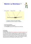
3M™ Ground Pro
Ground Integrity Meter
Model CTM051
User’s Guide
October 2014
78-9100-8544-4
Contents (Table des matières)
1.0
SAFETY INFORMATION (RENSEIGNEMENTS SUR LA SÉCURITÉ) .... 4
2.0
Environmental Conditions (Conditions environnementales) .......................... 12
3.0
Package Contents (Contenu de l’emballage) ................................................... 13
4.0
General Product Specifications (Spécifications générales du produit) ........... 13
5.0
Controls and Indicators (Contrôles et indicateurs) .......................................... 14
6.0
Parts Description (Description des pièces) ...................................................... 15
7.0
General (Alimentation) .................................................................................... 16
Power (Générale) .............................................................................................. 16
Installing the Battery (Installation de la pile) .................................................. 16
Low-Battery Indicator (Indicateur de pile faible) ............................................ 16
Turning Unit On and Off (Mise en marche et arrêt de l’unité) ....................... 17
Automatic Power Off (Arrêt automatique) ...................................................... 17
Checking the Battery Voltage (Vérification de la tension de la pile) .............. 18
8.0
Impedance Measurements (Impédancemétrie) ................................................ 18
Scaling (Mise à l’échelle)................................................................................. 18
Auto-Zeroing Test Leads (Essais de mise à zéro automatique) ...................... 19
9.0
Voltage On Ground Measurements (Tension des mesures au sol) .................. 20
AC Voltages (Tension alternative) ................................................................... 20
DC Voltage (Tension continue) ........................................................................ 20
Overload (Surcharge) ....................................................................................... 20
Using Reference with Voltage Measurements
(Utilisation de références avec les mesures de tension) .................................. 21
10.0 EMI Measurements (Mesures d’interférences électromagnétiques) ............... 22
Auto scale (Mise à l’échelle automatique) ...................................................... 22
Using Reference with EMI (Utilisation de références avec les mesures
d’interférence électromagnétique) ................................................................... 23
Hold Function (Fonction maintien) ................................................................. 24
11.0 Maintenance (Maintenance) ............................................................................. 25
12.0 Regulatory Information (Information réglementaire)...................................... 26
Warranty; Limited Remedy; Limited Liability.
(Garantie; Limite de recours; Limite de responsabilité)............................................ 29
1
Intended Use:
The 3M Ground Pro Ground Integrity Meter measures several important parameters
of grounding: ground impedance and high-frequency noise (EMI) on a ground.
This device is not intended to be used to measure mains voltage.
It is necessary to use proper equipment to check for stray voltage from mains prior to
using the Ground Integrity Meter to measure ground.
Ground connectivity is measured in accordance with ANSI 6.1. It is measured as
impedance in a way that is immune to parasitic signals on a ground. In addition to
monitoring the ground connection, the Ground Pro measures high frequency noise
(EMI) on the ground that is often present in a factory environment. Such interference
causes problems with the operation of equipment.
The device must be used as specified in this user guide in an indoor commercial/
industrial environment, and has not been evaluated for other uses or locations. If
the equipment is used in a manner not specified by the manufacturer, the protection
provided by the equipment may be impaired.
2
3M™ Ground Pro Ground Integrity
Meter Model CTM051
Safety Information
Please read, understand, and follow all safety information contained in these
instructions prior to the use of this device. Retain these instructions for future reference.
EXPLANATION OF SIGNAL WORD CONSEQUENCES
WARNING:
Indicates a potentially hazardous situation, which – if not avoided – could result in death
or serious injury and/or property damage.
CAUTION:
Indicates a potentially hazardous situation, which – if not avoided – may result in minor
or moderate injury and/or property damage.
NOTICE:
Indicates a potentially hazardous situation, which – if not avoided – may result in
property damage.
Summary of device labels containing safety information
WARNING:
To reduce the risks associated with hazardous voltage:
Do not replace battery while device is in use. Battery compartment is only intended to
be open with the device powered off.
Do not operate if the battery door is not in place.
WARNING:
Do not use on three-phase equipment.
WARNING
To reduce the risks associated with fire and explosion:
- Do not use in Hazardous Locations.
To reduce the risks associated with hazardous voltage and fire:
- Do not use this device outdoors or in wet or humid environments.
- Do not use this device outside of the operating conditions listed in this user manual.
To reduce the risks associated with hazardous voltage:
- Do not replace battery while device is in use. Battery compartment is only intended to be open with the
device powered off.
- Do not operate if the battery door is not in place.
- Do not use meter to test three-phase equipment.
- Do not use to measure mains voltage Disconnect circuit power and discharge all high-voltage capacitors
before testing resistance, continuity, diodes, or capacitance.
- Always use proper terminals and device settings.
- Check the test leads for continuity before use. Do not use if the readings are high or noisy.
- Do not use the meter or test leads if damaged or are not operating properly.
- Do not modify or attempt to service the meter or leads; there are no user serviceable parts. Return to 3M for service.
- Do not use the Meter or test leads outside of the operating conditions listed in this user guide.
- Keep fingers behind the finger guards on the leads.
- All personel using this device shall be certified or properly trained.
2
CAUTION:
To reduce the risks associated with environmental contamination:
Dispose of meter and all components in accordance with all applicable local and government regulations
NOTICE:
To reduce the risks associated with property damage:
- Before use, check that the meter is functioning correctly.
- Remove battery before long-term storage.
EXPLICATION DES CONSEQUENCES MOT SIGNAL
WARNING:
Indique une situation dangereuse, qui, si elle n’est pas évitée, pourrait provoquer la mort
ou des blessures graves.
CAUTION:
Indique une situation dangereuse, qui, si elle n’est pas évitée, pourrait provoquer des
blessures mineures ou modérées, ou des dégâts matériels.
NOTICE:
Indique une situation qui, si elle n’est pas évitée, pourrait provoquer des dégâts matériels.
SOMMAIRE DES LABELS DE L’APPAREIL CONTENANT DE
L’INFORMATION DE SÉCURITÉ
WARNING:
Pour réduire les risques associés aux tensions dangereuses :
- Ne pas remplacer la pile lorsque l’appareil est en cours d’utilisation. Le compartiment
de la pile doit uniquement être ouvert lorsque l’appareil est éteint.
- Ne pas utiliser l’appareil si le couvercle du porte-pile n’est pas en place.
WARNING:
Ne pas utiliser sur un équipement triphasé.
WARNING
Réduire les risques liés aux feux et aux explosions:
- Ne pas utiliser dans des emplacements dangereux.
Réduire les risques liés aux tensions et feux dangereux:
- Ne pas utiliser cet appareil à l’extérieur ou dans des environnements humides ou mouillées.
- Ne pas utiliser cet appareil en dehors des conditions d’exploitation répertoriés dans le manuel d’utilisation.
Réduire les risques liés à une tension dangereuse:
- Ne pas remplacer la pile lorsque l’appareil est en cours d’utilisation. Le compartiment de la pile doit
uniquement être ouvert lorsque l’appareil est éteint.
- Ne pas utiliser l’appareil si le couvercle du porte-pile n’est pas en place.
- Ne pas utiliser le multimètre pour tester les équipements triphasés.
- Ne pas appliquer plus que la tension nominale, indiquée sur compteur .
- L’alimentation du circuit de déconnexion et décharger tous les condensateurs à haute tension avant de
tester la résistance, la continuité, les diodes ou la capacité.
3
WARNING (cont.)
Réduire les risques liés à une tension dangereuse:
- Utiliser toujours les bornes et les paramètres de l’appareil.
- Vérifiez les cordons de la continuité avant l’utilisation. Ne pas utiliser si les lectures sont élevées ou
bruyantes.
- Ne pas utiliser l’appareil ou cordons de mesure s’ils sont endommagés ou ne fonctionnent pas correctement.
- Ne pas modifier ou tenter de réparer l’appareil ou les câbles; il n’y a aucune pièce réparable par l’utilisateur.
Retour à 3M pour le service.
- Ne pas utiliser le multimètre ou ses cordons en dehors des conditions d’exploitation répertoriés dans ce guide
d’utilisation.
- Gardez les doigts derrière les protège-doigts sur les pistes.
MISE EN GARDE:
Réduire les risques liés à la contamination de l’environnement:
- Éliminer mètres et tous les composants en conformité avec les réglementations locales et gouvernementales
applicable.
NOTICE:
Réduire les risques liés aux dommages à la propriété:
- Avant utilisation, vérifier que le compteur fonctionne correctement.
- Retirez la batterie avant stockage à long terme.
FCC
This equipment has been tested and found to comply with the limits for a Class B digital device, pursuant
to part 15 of the FCC Rules. These limits are designed to provide reasonable protection against harmful
interference in a residential installation. This equipment generates, uses and can radiate radio frequency energy
and, if not installed and used in accordance with the instructions, may cause harmful interference to radio
communications. However, there is no guarantee that interference will not occur in a particular installation. If
this equipment does cause harmful interference to radio or television reception, which can be determined by
turning the equipment off and on, the user is encouraged to try to correct the interference by one or more of the
following measures:
• Reorient or relocate the receiving antenna.
• Increase the separation between the equipment and receiver.
• Connect the equipment into an outlet on a circuit different from that to which the receiver is connected.
• Consult the dealer or an experienced radio/TV technician for help.
This device complies with Part 15 of the FCC Rules. Operation is subject to the following two conditions: (1) this
device may not cause harmful interference, and (2) this device must accept any interference received, including
interference that may cause undesired operation.
Industry Canada
This Class B digital apparatus complies with Canadian ICES-003.
Cet appareil numérique de la classe B est conforme á la NMB-003 du Canada.
4
Environmental Conditions
This equipment has been tested and found to be safe to operate within these
environmental conditions.
This is not a warranty of equipment performance within these conditions
Indoor use only
Ingress Protection: IPX0
Altitude: Up to 2,000 m
Pollution degree 2
Temperature: Maximum 110°F/43°C Minimum 50°F/10°C
Humidity: Maximum relative humidity 80% for temperatures up to 31°C
decreasing linearly to 50% relative humidity at 40°C
Package Contents
Your 3M™ Ground Pro Ground Integrity Meter should include the following*:
3M™ Ground Pro Ground Integrity Meter
1 pair of probe leads
9V battery included
General Product Specification
Your 3M™ Ground Pro Ground Integrity Meter should include the following*:
Power
Battery 9V Alkaline
Dimensions (approx.)
4.5" x 2.4" x 1.1"
114 mm x 60 mm x 28 mm
Weight (approx.)
223 g
5
The 3M™ Ground Pro Ground Integrity Meter is a comprehensive instrument that
measures the ground connection of your equipment in accordance with ANSI 6.1 and
ANSI/ESDA S.20.20 standards. In addition to measuring ground impedance, it also
measures AC and DC voltage on the ground as well as the presence of high-frequency
noise or electromagnetic interference (EMI) on the ground, alerting you to possible
functionality problems, such as tool lockups, erratic behavior and parametric errors.
Controls and Indicators
P ow er
C
Turns the power on and off. Hold for a few seconds to turn the unit off. Also
resets some parameters.
Switches the unit into impedance measurement mode.
E M I
V
R e f.
H o ld
Switches the unit into high-frequency noise (EMI) measurement mode.
Switches the unit into AC and DC voltage mode.
Sets up the reference for measurements and alarms.
Freezes the display/and shows the maximum measured value.
Adjusts the scale for some parameters and adjusts reference values.
Display backlight on/off
6
Parts Description
Please refer to the rest of this User’s Guide for detailed explanations of each control,
indicator and connection.
Banana Jacks
Keypad
Display
Battery Compartment
(on the back)
7
General
Power
The 3M™ Ground Pro Ground Integrity Meter uses a 9V alkaline battery. Do not use
any other battery. If you are not using your 3M™ Ground Pro Ground Integrity Meter
for an extended period of time, remove the battery from the unit in order to prevent
damage caused by a possible battery leakage.
Installing the Battery
Remove the screw from the battery lid. Slide off the battery lid at the back of the
3M™ Ground Pro Ground Integrity Meter and attach the 9V battery to the battery clip.
Observe the polarity of the battery. Slide in the battery lid and secure it back with
the screw.
8
Low-Battery Indicator
When battery voltage gets low (less than 20% capacity
remains), the low battery indicator on the display
appears. At this point, replace the battery.
Turning Unit On and Off
0
2
4
6
Low-Battery Indication
ON
Press the button. The battery voltage will be displayed for a moment in both P o w e r
C
volts and percentage of the full capacity. If the battery voltage is too low even
to indicate low-voltage status on the display or if the self-diagnostic fails, you will hear
a beep and the unit will shut itself off. If the battery is completely drained, there may
not even be a beep. Please replace the battery. Use proper disposal method per local
regulatory requirements.
OFF
Press the Power/C button for at least two seconds. The 3M™ Ground Pro
Ground Integrity Meter will turn off.
F
Automatic Power Off
In order to save battery life, the 3M™ Ground Pro Ground
Integrity Meter has an automatic power-off (APO) feature
that will turn the unit off after approximately 10 minutes
if no buttons are pressed. You can disable or enable APO
by depressing the F button several times until you get to the screen shown above. You
can then enable or disable APO using the Up and Down arrow buttons. Please keep in
mind that with APO disabled, the battery life will be shorter.
Checking the Battery Voltage
F
Press the F button several times until you get this screen.
The upper display shows the battery voltage, and the
lower display shows the percentage of usable battery
life left.
V
%
0
2
Lin
4
6
9
Impedance Measurements
Press the Ohm button to go to ground impedance
mode. You should see a screen similar to the one
shown on the right. The impedance mode is indicated
by “OH” on the bottom display line.
Scaling
0
2
4
Impedance Screen
The 3M™ Ground Pro Ground Integrity Meter has
four different scales for measuring ground impedance.
Choose the appropriate scale for your measurements using the Up and Down
arrow buttons.
O h m s
X .X X X O h m s
0
2
4
6
X .X X O h m s
X X .X O h m s
XXXO hm s
8
Auto-Zeroing Test Leads
Test leads offer added impedance and may alter
measurement results, especially at a lower scale. In
order to take impedance of test leads into account, short
the ends of the test leads together and press the Function
button (F) until you see the screen shown on Function
button (F) until you see the screen shown on the right.
In a few seconds, this screen will disappear and you
will hear a short beep. The 3M™ Ground Pro Ground
Integrity Meter will return to normal measurement
mode. Now when the test leads are shorted together,
the display should show zero Ohms, even though the
test leads may have some impedance. The correction
factor will be saved in the internal memory.
10
F
0
2
4
6
If the test leads are not shorted properly or become accidentally disconnected during
this process, auto-zero will fail and you should hear a long beep before the display
returns to the impedance measurement screen. In this case you will need to repeat this
process again.
Voltage on Ground Measurements
Do not use to measure mains voltage.
The presence of voltage on a ground is never desirable. The 3M™
Ground Pro Ground Integrity Meter can measure both AC and DC
voltages on a ground.
AC Voltage
Press the V button once. The 3M™ Ground Pro Ground
Integrity Meter will switch to AC voltage measurement
mode and you should see a screen similar to one on the
right. You can adjust the measurement scale using the
Up and Down arrow buttons.
DC Voltage
Press the V button again to switch to DC voltage measurement mode. You
should see a screen similar to the one on the right. As in AC mode, you can
adjust the measurement scale using the Up and Down arrow buttons.
Overload
If voltage on the ground is above the maximum level on a particular scale, you
should see an overload indicator such as the one
on the right. In such a case, go to the next scale
using the Up arrow button.
0
2
4
6
8
10
11
Using Reference with Voltage Measurements
The Reference function helps to set limits at which an audio alarm sounds
to indicate that the measured
impedance is below the
O hm s
specified limit. Unlike a
regular multimeter, the
3M™ Ground Pro Ground
R ef
Integrity Meter allows
Normal
measurements
you to specify an exact
screen
impedance value at which
the instrument will provide
0
2
4
6
8
10
an audio indication. In
Impedance mode, press the
REF
Ref. button. You should see
Impedance
a screen similar to the one
in Ohms
on the right with the REF
Threshold
indicator on. The top line of
4
6
8
10
the display shows the current
impedance value (in this
example it is an open circuit)
and the bottom line shows the reference level. Adjust the reference level by
using the Up and down arrow buttons. Now when the impedance is below
the reference value, you should hear a beep. The reference value is set for
a particular range – you may need to readjust it for a different range. The
reference value will be saved in the internal memory.
12
EMI Measurements
High frequency noise (EMI) on a ground causes equipment malfunction and
damage to sensitive components. The 3M™ Ground Pro Ground Integrity
Meter measures
high-frequency noise
EMI
on a ground in a
AVG
PEAK
wide frequency and
V
dynamic range.
Peak EMI in V
High-frequency
noise is measured
in two different
units — volts and
dBuV. The latter is a
logarithmic measure
of voltage where 0dB
is referenced to 1uV.
0
2
V
4
AVG
0
2
4
Average EMI in V
Relative peak value
PEAK
dB
µV
dB
µV
Peak EMI in dBuV
Average EMI in dBuV
Relative peak value
In order to measure
EMI on a ground, press the EMI button. The screen will show the average
value of the high-frequency signal in Volts on the top display line and the
magnitude of the envelope peak of the signal (i.e. transients or spikes) on
the bottom line. By pressing the EMI button one more time you can switch
to dBuV units, as shown above.
Autoscale
The 3M™ Ground Pro Ground Integrity Meter uses auto scaling in EMI
mode. No scale switching is necessary.
13
Using Reference with EMI
Reference mode is helpful if you wish to
hear an audio alarm whenever the EMI
signal exceeds a certain level. In order to
use this mode, depress the REF button while
in any of the EMI screens. You should see
the REF indicator at the top of the display.
The bottom line of the display will now
show the reference value of the average
signal instead of the peak value of the signal.
Adjust the reference level using the Up and
Down arrow buttons. Now whenever the
average value of the EMI signal exceeds this
reference level, an audio alarm will sound.
EMI
Ref.
AVG
V
0
2
AVG
14
PEAK
Peak value
V
4
REF
AVG
V
Average
value
V
4
Hold Function
Please note that if you power down the
Ground Pro while in any of these modes,
it will collect the maximum value of the
measured parameter for as long as this mode
Normal
measurements
screen
V
4
By pressing the REF button again, you can
adjust the reference level for the peak signal
as shown on the right.
Pressing the Hold button once while in any
measurement mode will cause the 3M™
Ground Pro Ground Integrity Meter to enter
the Hold mode. The display will freeze,
showing the value at the moment the button
was pressed. Pressing the Hold button
a second time the display will show the
maximum value of the signal accumulated
from the moment of pressing the button.
PEAK
Hold
AVG
PEAK
V
0
2
V
4
HOLD
AVG
PEAK
V
0
2
MAX
AVG
PEAK
V
0
2
4
Screen is frozen
V
4
HOLD
Normal
measurements
screen
V
Max. signal values
are shown
is active. Please note that if you power down the 3M™ Ground Pro Ground Integrity
Meter while in any of these modes, it will remain in the same mode when the unit is
powered up again.
Pressing the Hold button one more time puts the Ground Pro back into regular mode.
15
Maintenance
Procedures for Cleaning and Decontamination
Clean using a dry brush or vacuum cleaner around the device. In case of contact
malfunction, clean contacts using a contact cleaner or a brush and tighten all
connections.
Repairs and Servicing
Do not attempt to repair the product yourself. Contact a 3M
sales representative or authorized dealer to request inspection
and repair. There are no user-serviceable parts.
Device Calibration
Contact a 3M sales representative or authorized dealer to
request for product calibration if needed.
16
3M™ Ground Pro Ground Integrity Meter Model
CTM051
Regulatory Information
China RoHS
Electronic Industry Standard of the People’s Republic of China, SJ/T11363-2006,
Requirements for Concentration Limits for Certain Hazardous Substances in
Electronic Information Products
This symbol, per Marking for the Control of Pollution Caused by Electronic Information
Products, SJ/T11364-2006, means that the product or part
does contain a substance, as detailed in the chart below, in
excess of the following maximum concentration values in
any homogeneous material: (a) 0.1% (by weight) for lead,
mercury, hexavalent chromium, polybrominated biphenyls
or polybrominated diphenyl ethers; or (b) 0.01% (by weight)
for cadmium. Unless otherwise stated by 3M in writing, this
information represents 3M’s best knowledge and belief based
upon information provided by third party suppliers to 3M.
This numerical reference should not be construed as a representation regarding the
product’s life or an extension of a product warranty. In the event any product is proven
not to conform with 3M’s Regulatory Information Sheet, then 3M’s entire liability and
buyer’s exclusive remedy, will be at 3M’s option either: (i) replacement of product with
a conforming product, or (ii) refund of the purchase price paid by buyer for each nonconforming product, within a reasonable time after written notification of said nonconformance and return of said product to 3M. 3M shall not under any circumstances
be liable for direct, incidental, special, or consequential damages (including but not
limited to loss of profits, revenue, or business) related to or arising out of this certification,
including, the use, misuse or inability to use the product. Unless stated otherwise in
writing, the foregoing language cannot be waived, modified, or supplemented in any
manner whatsoever.
17
产品中有毒有害物质或元素的名称及含量
Name and Content of Hazardous Substances or Elements
(Nom et contenu des substances ou des éléments dangereux)
有毒有害物质或元素
(Hazardous Substances or Elements)
(Substances ou éléments dangereux)
部件名称
(Part or Component Name)
(Nom de la pièce ou du composant)
铅
(Pb)
汞
镉
(Hg) (Cd)
六价铬
(Cr(VI))
多溴
联苯
多溴二
苯醚
(PBB)
(PBDE)
电容引脚
×
○
○
○
○
○
电位器中的电阻油墨
×
○
○
○
○
○
二极管焊接部
×
○
○
○
○
○
二极管电镀
×
○
○
○
○
○
印刷电路板焊盘/安装孔
×
○
○
○
○
○
电阻引脚
×
○
○
○
○
○
电阻电镀部
×
○
○
○
○
○
连接器
×
○
○
○
○
○
三极管
×
○
○
○
○
○
电感器
×
○
○
○
○
○
电磁干扰滤波器
×
○
○
○
○
○
装置的焊接部
×
○
○
○
○
○
IC焊接部
(Solder in IC)
(Soudure d’un circuit intégré)
×
○
○
○
○
○
(Termination in capacitor) (Terminaison
d’un condensateur)
(Resistor ink in potentiometer)
(Encre du résistor d’un potentiomètre)
(Solder in diode)
(Soudure d’un diode)
(Finish in diode) (Fini d’un diode)
(Terminations in PCBs)
(Terminaisons des PCB)
(Terminations in resistors)
(Terminaisons des résistors)
(Plating in resistors)
(Placage des résistors)
(Connector) (Connecteur)
(Transistor) (Transistor)
(Inductor) (Inducteur)
(EMI filter) (Filtre anti-perturbation
électromagnétique)
(Solder in instrument)
(Soudure d’un instrument)
18
3M™ Ground Pro Ground Integrity Meter Model CTM051
Impedance
Range
Range: 0.000 – 1.999 Ohm, 2% + 0.01 Ohm
Range: 00.00 – 19.99 Ohm, 1% + 0.05 Ohm
Range: 000.0 – 199.9 Ohm, 1% + 0.5 Ohm
Range: 0000 – 1999 Ohm, 1% + 5 Ohm
Automatic auto-zero for test leads
EMI (noise on ground)
Bandwidth
9kHz – 450MHz
Measurement Range
10mV – 5Vpeak
80dBuV –134 dBuV
Measurement Type
Average
Peak
Voltage on Ground
AC (50 – 500 Hz)
0.001 – 10 V RMS
DC
0.001 – 10 V
General
Power
Battery 9V Alkaline
Dimensions (approx.)
4.5” x 2.4” x 1.1”
114 mm x 60 mm x 28 mm
19
有毒有害物质或元素
(Hazardous Substances or Elements)
(Substances ou éléments dangereux)
部件名称
(Part or Component Name)
(Nom de la pièce ou du composant)
铅
(Pb)
汞
镉
(Hg) (Cd)
六价铬
(Cr(VI))
多溴
联苯
多溴二
苯醚
(PBB)
(PBDE)
蜂鸣器焊接部
×
○
○
○
○
○
音频插孔
×
○
○
○
○
○
(Solder in buzzer) (Soudure dans un
bouton-signal)
(Audio jack) (Prise audio)
“○:表示该有毒有害物质在该部件所有均质材料中的含量均在SJ/T11363-2006 标准规
定的限量要求以下。(Indicates that this hazardous substance contained in all of the homogeneous materials for
this part is below the limit requirement in SJ/T11363-2006.) (Indique que cette substance dangereuse contenue dans
tous les matériaux homogènes de cette pièce se situe sous la limite permise conformément aux exigences de la norme
SJ/T11363-2006.)
×:表示该有毒有害物质至少在该部件的某一均质材料中的含量超出SJ/T11363-2006
标准规定的限量要求。(Indicates that this hazardous substance contained in at least one of the homogeneous
materials used for this part is above the limit requirement in SJ/T11363-2006.)” (Indique que cette substance
dangereuse contenue dans au moins un des matériaux homogènes de cette pièce se situe au-dessus de la limite
permise conformément aux exigences de la norme SJ/T11363-2006.)
This is the EU symbol for equipment that is covered under the Waste from Electrical and Electronic Equipment
(WEEE) directive per CENELEC Specification 5041. It indicates that certain products should not be discarded in the
trash, but rather should be recycled. This applies to all electronic pluggable and battery powered products.
Ceci est le symbole de l’UE pour l’équipement assujetti à la directive relative aux déchets d’équipements électriques
et électroniques (DEEE) conformément à la spécification 5041 du CENELEC. Cette directive stipule que certains
produits ne doivent pas être jetés aux ordures, mais doivent plutôt être recyclés. Elle s’applique à tous les appareils
électroniques enfichables et à tous les produits alimentés par une pile.
Important Notice
All statements, technical information, and recommendations related to 3M’s products are based on information believed to be reliable,
but the accuracy or completeness is not guaranteed. Before using this product, you must evaluate it and determine if it is suitable for your
intended application. You assume all risks and liability associated with such use. Any statements related to the product which are not
contained in 3M’s current publications, or any contrary statements contained on your purchase order shall have no force or effect unless
expressly agreed upon, in writing, by an authorized officer of 3M.
Warranty; Limited Remedy; Limited Liability.
This product will be free from defects in material and manufacture for a period of one (1) year from the time of purchase. 3M MAKES
NO OTHER WARRANTIES INCLUDING, BUT NOT LIMITED TO, ANY IMPLIED WARRANTY OF MERCHANTABILITY OR FITNESS FOR A
PARTICULAR PURPOSE.
If this product is defective within the warranty period stated above, your exclusive remedy shall be, at 3M’s option, to replace or repair the
3M product or refund the purchase price of the 3M product. Except where prohibited by law, 3M will not be liable for any indirect,
special, incidental or consequential loss or damage arising from this 3M product, regardless of the legal theory asserted.
Electronics Materials
Solutions Division
Static Control Products
6801 River Place Blvd.
Austin, TX 78726-9000
866-722-3736
www.3Mstatic.com
3M is a trademark of 3M Company.
Please recycle. Printed in U.S.A.
© 3M 2014. All rights reserved.
78-9100-8544-4