1
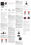
Type BBS-3F
Inline inspection glass full view and standard design
Linienschauglas Vollsicht und Standardausführung
Indicateur de débit en ligne indication totale et modèle standard
Operating Instructions
Bedienungsanleitung
Manuel d‘utilisation
Bürkert Fluid Control Systems
Sales Center
Christian-Bürkert-Str. 13-17
D-74653 Ingelfingen
Tel. + 49 (0) 7940 - 10 91 111
Fax + 49 (0) 7940 - 10 91 448
E-mail: [email protected]
International address
www.burkert.com → Bürkert → Company → Locations
Manuals and data sheets on the Internet: www.burkert.com
Bedienungsanleitungen und Datenblätter im Internet: www.buerkert.de
Instructions de service et fiches techniques sur Internet : www.buerkert.fr
© 2014 Bürkert Werke GmbH
Operating Instructions 1402/00_EU-ML_00810320 / Original DE
www.burkert.com
Type BBS-3F
1. THE OPERATING INSTRUCTIONS
The operating instructions contain important information.
• Read the instructions carefully and follow the safety instructions in
particular.
• Keep the instructions in a location where they are available to every
user.
• The liability and warranty for the product do not apply if the procedures in the instructions are not observed.
1.1. Symbols
→→designates a procedure which you must carry out.
Warning of injuries:
DANGER!
Immediate danger! Serious or fatal injuries.
WARNING!
Possible danger! Serious or fatal injuries.
CAUTION!
Danger! Moderate or minor injuries.
Warning of damage:
NOTE!
2. INTENDED USE
Non-authorized use of the Type BBS-3F inline inspection
glass may be dangerous to people, nearby equipment and the
environment.
• Type BBS-3F has been designed as an inline inspection glass for
pipelines for the flow of fluids in the sterile area.
• Use according to the authorized data, operating conditions, and
conditions of use specified in the contract documents and operating
instructions.
• Correct transportation, storage and installation, as well as careful use and maintenance are essential for reliable and faultless
operation.
• Use the product only as intended.
2.1. Restrictions
If exporting the products, observe any existing restrictions.
2.2. Definitions of terms
The term “product” used in these instructions always refers to the inline
inspection glass Type BBS-3F.
english
2
3. BASIC SAFETY INSTRUCTIONS
4. GENERAL INFORMATION
These safety instructions do not take into account any contingencies and
events which may arise during the installation, operation and maintenance
of the product.
4.1. Contact address
Danger – high pressure and discharge of medium!
• Before loosening the nuts or screws, always turn off the pressure
and relieve the lines.
• Wear protective equipment if media is hazardous.
General hazardous situations
• Do not make any internal or external changes to the product.
• Ensure that the system cannot be activated unintentionally.
• Installation and maintenance work may be carried out only by
authorized technicians with the appropriate tools.
• The product may be operated only when in perfect condition and in
consideration of the operating instructions.
• As far as inspection, maintenance and repairs are concerned,
observe national provisions of the country in which the connection
elements are installed.
• The general rules of technology apply to application planning and
operation of the product.
Germany
Bürkert Fluid Control Systems
Sales Center
Christian-Bürkert-Str. 13-17
D-74653 Ingelfingen
Tel. + 49 (0) 7940 - 10 91 111
Fax + 49 (0) 7940 - 10 91 448
E-mail: [email protected]
International
Contact addresses can be found on the final pages of the printed
operating instructions. And also on the Internet at: www.burkert.com
4.2. Warranty
The warranty is only valid if the product is used as intended in
accordance with the specified application conditions.
4.3. Information on the Internet
The operating instructions and data sheets for Type BBS-3F inline
inspection glass can be found on the Internet at: www.burkert.com
english
5. TECHNICAL DATA
5.1. Conformity
The inline inspection glass Type BBS-3F conforms to the EC directives according to the EC Declaration of Conformity.
5.4. Sealing materials
Seal material
EPDM
FKM
Operating temperature
–40 °C to 90 °C, briefly up to 140 °C
–20 °C to 200 °C
5.2. Standards (if applicable)
Tab. 1: Sealing materials BBS-3F inline inspection glass
The applied standards which are used to demonstrate compliance with
the EC Directives are listed in the EC type test certificate and/or the
EC Declaration of Conformity.
5.5. General technical data
5.3. Identification
Information on material, pipe and connection dimensions can be found
on the stamping on the product. The identification number of the
product can be found on the supplied 3.1 certificate.
Material
Fig. 1:
4
Material
batch number
Nominal connection
diameter with pipe standard
Example of identification of the product
english
comes into contact
Stainless steel 1.4435
with medium
BN2 (316L)
does not comes into Stainless steel 1.4401
Material
contact with medium or equivalent
Glass
Borosilicate glass
O-ring
EPDM/FKM
Pipe dimensions
see identification on product (“Fig. 1”)
Permitted application Depending on sealing material,
temperature
see “Tab. 1”
Ambient temperature –20 °C to +80 °C
Media
Fluids
Operating pressure –1 to +8 bar (depending on the temperature)
3
Type BBS-3F
6. ASSEMBLY
6.1. Welding in the inline inspection glass
NOTE!
WARNING!
Danger – high pressure and discharge of medium!
• When working on the product or the system, always switch off the
pressure and relieve the lines.
• Wear protective equipment if media is hazardous.
Risk of injury from improper assembly!
• Installation must only be carried out by authorized technicians and
with the appropriate tools!
• Secure system from unintentional activation.
Leak due to damaged sealing elements!
• Do not weld in the assembled product. It is essential to remove
the O-ring and glass tube before welding and to protect them from
dust, flying sparks and other influences!
Leak due to damaged sealing contour!
• To ensure the sealing function, protect the sealing contour during
installation, welding and cleaning procedures.
→→Connect the parts positively in a protective gas shield.
When cleaning the weld seam by grinding or acid cleaning, observe
the following before assembling the connection:
•Carefully remove all grinding dust and acid-cleaning residue.
•Do not damage the label.
•There must be no material abrasion on the sealing edges. Material
abrasion will result in sharp-edged sealing contours and a damaged seal.
•Check sealing contour for damage.
We recommend preparing a welding report.
english
6.2. Assembling orbital inline inspection glass
7
6
5
Fig. 2:
4
2
1
4
3
2
5
6 7
Assembling orbital inline inspection glass (with union nut)
6.3. Assembling standard inline inspection glass
5
Fig. 3:
→→Insert both O-rings (2) by hand (do not use any tools or sharp
implements) into the two designated grooves in the inspection
glass holder (1).
→→Carefully push glass (3) into the inspection glass holder. Ensure
that the O-rings are in the correct position.
→→Attach an O-ring (4) and a liner (5) to each side (do not use any
tools or sharp implements) and secure with the union nuts (6).
→→Tighten union nuts and secure with retaining rings (7).
5
4
2
1
2
3
4
5
Assembling standard inline inspection glass
→→Insert both O-rings (2) by hand (do not use any tools or sharp
implements) into the two designated grooves in the inspection
glass holder (1).
→→Carefully push glass (3) into the inspection glass holder. Ensure
that the O-rings are in the correct position.
→→Attach an O-ring (4) and a connecting piece (5) to each side (do
not use any tools or sharp implements).
→→Tighten connecting pieces.
english
6
6.4. Assembling full view inline inspection glass
5
6
Fig. 4:
1
3 4
2
7
4 3
1
5
6
Assembling full view inline inspection glass
→→In each flange (1) insert two O-rings (3 +4) by hand (do not use
any tools or sharp implements).
→→Push glass (7) into one of the two flanges. Ensure that the O-rings
are in the correct position.
→→Also insert spacer bolts (2) into the designated bores, secure with
7. START-UP
WARNING!
Risk of injury from improper operation!
Improper operation may result in injuries as well as damage to the
product and the surrounding area.
• Before start-up, ensure that the operating personnel are familiar
with and completely understand the contents of the operating
instructions.
• Observe the safety instructions and intended use.
• Only adequately trained personnel may start up the equipment/the
product.
• Following assembly, ensure a controlled restart.
• When starting up the equipment, ensure that no unauthorized voltage increases and pressure surges can occur.
washers (5) and nuts (6).
→→Attach second flange, secure with washers and nuts.
→→Tighten nuts.
6.5. Disassembly
Disassembly is in reverse sequence to assembly.
english
7
Type BBS-3F
8. MAINTENANCE
NOTE!
Damage to the sealing elements when cleaning the pipeline
systems.
• Clean the pipeline systems preferably with a cleaning agent which
does not damage the sealing elements.
• Do not clean with wire brushes or machines which cause abrasion
of the surface.
• When using mechanical pipeline monitoring devices, ensure
that they do not damage the sealing elements (also the sealing
contour).
Damaged sealing elements must be replaced!
WARNING!
Danger – high pressure and discharge of medium!
• Before loosening the nuts or screws, always turn off the pressure
and relieve the lines.
• Wear protective equipment if media is hazardous.
• Nuts or screws may be retightened on pressurized lines only by
technicians in consideration of special precautions.
• When shutting down the equipment, ensure that no unauthorized
voltage increases and pressure surges can occur.
• Following maintenance, ensure a controlled restart.
Have the product serviced regularly by technicians! We recommend
a maintenance interval of 6 months.
Inspection and maintenance work includes in particular monitoring and
ensuring the
•leak-tightness,
•identification,
•proper mode of operation of the safety and warning devices.
english
8
9. SPARE PARTS
CAUTION!
Risk of injury and/or damage by the use of incorrect parts!
Incorrect accessories and unsuitable spare parts may cause injuries
and damage the product and the surrounding area.
• Use only original accessories and original spare parts from Bürkert.
The spare part set for the inline inspection glass Type BBS-3F includes:
O-rings, inspection glass
The order numbers for the spare part sets can be found on the corresponding data sheet on the Internet.
10. TRANSPORTATION, STORAGE,
DISPOSAL
NOTE!
Transport damage!
Inadequately protected products may be damaged during
transportation.
• Transport the product in a firmly assembled state, protected against
moisture and dirt, in shock-resistant packaging.
Incorrect storage may damage the product.
• Prevent the temperature from exceeding or dropping below the
permitted storage temperature.
• Store the product in a dry and dust-free location!
• Store O-rings dry and protected from UV radiation and for not
longer than 3 years.
• Storage temperature –40 to +80 °C.
Damage to the environment caused by products contaminated
with media.
• Dispose of the product and packaging in an environmentally friendly
manner!
• Observe applicable disposal and environmental regulations.
english
9
Type BBS-3F
Inline inspection glass full view and standard design
Linienschauglas Vollsicht und Standardausführung
Indicateur de débit en ligne indication totale et modèle standard
Operating Instructions
Bedienungsanleitung
Manuel d‘utilisation
Bürkert Fluid Control Systems
Sales Center
Christian-Bürkert-Str. 13-17
D-74653 Ingelfingen
Tel. + 49 (0) 7940 - 10 91 111
Fax + 49 (0) 7940 - 10 91 448
E-mail: [email protected]
International address
www.burkert.com → Bürkert → Company → Locations
Manuals and data sheets on the Internet: www.burkert.com
Bedienungsanleitungen und Datenblätter im Internet: www.buerkert.de
Instructions de service et fiches techniques sur Internet : www.buerkert.fr
© 2014 Bürkert Werke GmbH
Operating Instructions 1402/00_EU-ML_00810320 / Original DE
www.burkert.com
Typ BBS-3F
1. DIE BEDIENUNGSANLEITUNG
Die Bedienungsanleitung enthält wichtige Informationen.
• Anleitung sorgfältig lesen und besonders die Hinweise zur Sicherheit
beachten.
• Anleitung so aufbewahren, dass sie jedem Benutzer zur Verfügung
steht.
• Haftung und Gewährleistung für das Produkt entfällt, wenn die
Anweisungen der Anleitung nicht beachtet werden.
1.1. Darstellungsmittel
→→markiert einen Arbeitsschritt, den Sie ausführen müssen.
Warnung vor Verletzungen:
GEFAHR!
Unmittelbare Gefahr! Schwere oder tödliche Verletzungen.
WARNUNG!
Mögliche Gefahr! Schwere oder tödliche Verletzungen.
VORSICHT!
Gefahr! Mittelschwere oder leichte Verletzungen.
2. BESTIMMUNGSGEMÄSSER
GEBRAUCH
Bei nicht bestimmungsgemäßem Gebrauch des Typs BBS-3F
Linienschauglas können Gefahren für Personen, Anlagen in der
Umgebung und die Umwelt entstehen.
• Typ BBS-3F ist als Linienschauglas in Rohrleitungen zum Durchfluss von Fluiden im sterilen Bereich konzipiert.
• Für den Einsatz die in den Vertragsdokumenten und der Bedienungsanleitung spezifizierten zulässigen Daten, Betriebs- und Einsatzbedingungen beachten.
• Voraussetzungen für den sicheren und einwandfreien Betrieb sind
sachgemäßer Transport, sachgemäße Lagerung und Installation
sowie sorgfältige Bedienung und Instandhaltung.
• Setzen Sie das Produkt nur bestimmungsgemäß ein.
2.1. Beschränkungen
Bei der Ausfuhr der Produkte gegebenenfalls bestehende Beschränkungen beachten.
2.2. Begriffsdefinition
Warnung vor Sachschäden:
HINWEIS!
Der in dieser Anleitung verwendete Begriff „Produkt“ steht immer für das
Linienschauglas Typ BBS-3F.
deutsch
10
3. GRUNDLEGENDE
SICHERHEITSHINWEISE
4. ALLGEMEINE HINWEISE
Diese Sicherheitshinweise berücksichtigen keine Zufälligkeiten und
Ereignisse, die bei Montage, Betrieb und Wartung des Produkts auftreten
können.
Deutschland
Bürkert Fluid Control Systems
Sales Center
Christian-Bürkert-Str. 13-17
D-74653 Ingelfingen
Tel. + 49 (0) 7940 - 10 91 111
Fax + 49 (0) 7940 - 10 91 448
E-mail: [email protected]
International
Die Kontaktadressen finden Sie auf den letzten Seiten der gedruckten
Bedienungsanleitung. Außerdem im Internet unter: www.burkert.com
Gefahr durch hohen Druck und Mediumsaustritt!
• Vor dem Lösen von Muttern oder Schrauben unbedingt den Druck
abschalten und Leitungen entlasten.
• Bei gefährlichen Medien Schutzausrüstung tragen.
Allgemeine Gefahrensituationen
• Am Produkt keine inneren oder äußeren Veränderungen vornehmen.
• Beachten, dass die Anlage nicht unbeabsichtigt betätigt werden kann.
• Installations- und Instandhaltungsarbeiten dürfen nur von autorisiertem Fachpersonal mit geeignetem Werkzeug ausgeführt werden.
• Das Produkt nur in einwandfreiem Zustand und unter Beachtung der
Bedienungsanleitung betreiben.
• Bei Inspektion, Wartung und Instandsetzung nationale Bestimmungen
des Aufstellungslands beachten.
• Für die Einsatzplanung und den Betrieb des Produkts die allgemeinen Regeln der Technik einhalten.
4.1. Kontaktadresse
4.2. Gewährleistung
Voraussetzung für die Gewährleistung ist der bestimmungsgemäße
Gebrauch des Produkts unter Beachtung der spezifizierten
Einsatzbedingungen.
4.3. Informationen im Internet
Bedienungsanleitungen und Datenblätter zum Typ BBS-3F Linienschauglas finden Sie im Internet unter: www.buerkert.de
deutsch
5. TECHNISCHE DATEN
11
5.4. Dichtungsmaterialien
5.1. Konformität
Das Linienschauglas Typ BBS-3F ist konform zu den EG-Richtlinien
entsprechend der EG-Konformitätserklärung.
Dichtwerkstoff
EPDM
FKM
Betriebstemperatur
–40 °C bis   90 °C, kurzzeitig bis 140 °C
–20 °C bis 200 °C
5.2. Normen (soweit anwendbar)
Tab. 1: Dichtungsmaterialien BBS-3F Linienschauglas
Die angewandten Normen, mit denen die Konformität mit den EG-Richtlinien nachgewiesen wird, sind in der EG-Baumusterprüfbescheinigung
und/oder der EG-Konformitätserklärung nachzulesen.
5.5. Allgemeine technische Daten
5.3. Kennzeichnung
Angaben zu Material, Rohr- und Anschlussmaß sind der Prägung auf
dem Produkt zu entnehmen. Die Identnummer des Produkts entnehmen
Sie bitte dem mitgelieferten 3.1-Zeugnis.
Werkstoff
Bild 1:
12
MaterialAnschlussnennweite
chargennummer mit Rohrnorm
Beispiel für die Kennzeichnung des Produkts
deutsch
Material
mediumberührt
Edelstahl 1.4435 BN2 (316L)
nicht
Edelstahl 1.4401 oder Ähnliches
mediumberührt
Glas
Borosilikatglas
O-Ring
EPDM/FKM
siehe Kennzeichnung auf Produkt („Bild 1“)
je nach Dichtungsmaterial, siehe „Tab. 1“
Rohrmaße
zulässige
Einsatztemperatur
Umgebungs–20 °C bis +80 °C
temperatur
Medien
Fluide
Betriebsdruck
–1 bis +8 bar (in Abhängigkeit von Temperatur)
Typ BBS-3F
6. MONTAGE
6.1. Einschweißen des Linienschauglases
HINWEIS!
WARNUNG!
Gefahr durch hohen Druck und Mediumsaustritt!
• Bei Arbeiten am Produkt oder der Anlage unbedingt den Druck
abschalten und Leitungen entlasten.
• Bei gefährlichen Medien Schutzausrüstung tragen.
Verletzungsgefahr bei unsachgemäßer Montage!
• Die Montage darf nur autorisiertes Fachpersonal mit geeignetem
Werkzeug durchführen!
• Anlage vor unbeabsichtigtem Betätigen sichern.
Undichtheit durch beschädigte Dichtelemente!
• Das Produkt nicht in zusammengebautem Zustand einschweißen.
Vor dem Schweißen unbedingt O-Ring und Glasrohr entfernen und
vor Staub, Funkenflug und anderen Einflüssen schützen!
Undichtheit durch beschädigte Dichtkontur!
• Zur Sicherstellung der Dichtfunktion die Dichtkontur während
Montage, Schweißen und Reinigungsverfahren schützen.
→→Verbindung formschlüssig unter Schutzgas heften.
Bei Schweißnahtreinigung mittels Schleifen oder Beizen vor dem
Zusammenbau der Verbindung beachten:
•Alle Schleifstaub- und Beizereste sorgfältig entfernen.
•Beschriftung nicht beschädigen.
•An den Dichtkanten darf kein Materialabtrag vorgenommen werden.
Materialabtrag führt zu scharfkantigen Dichtkonturen und damit zur
Verletzung der Dichtung.
•Dichtkontur auf Beschädigung kontrollieren.
Wir empfehlen die Erstellung eines Schweißprotokolls.
deutsch
6.2. Montage Linienschauglas orbital
7
6
5
Bild 2:
4
2
1
3
2
4
6.3. Montage Linienschauglas Standard
5
6 7
Montage LSG orbital (mit Überwurfmutter)
5
Bild 3:
→→Beide O-Ringe (2) von Hand (keine Werkzeuge oder scharfen
Hilfsmittel verwenden) in die beiden hierfür vorgesehenen Rillen im
Schauglashalter (1) einlegen.
→→Glas (3) vorsichtig in Schauglashalter schieben. Hierbei auf die
korrekte Lage der O-Ringe achten.
→→Von beiden Seiten je einen O-Ring (4) und einen Bundstutzen (5)
anbringen (keine Werkzeuge oder scharfen Hilfsmittel verwenden)
und durch die Überwurfmuttern (6) sichern.
→→Überwurfmuttern festziehen und mit Sicherungsringen (7) sichern.
4
2
1
2
3
4
5
Montage LSG Standard
→→Beide O-Ringe (2) von Hand (keine Werkzeuge oder scharfen
Hilfsmittel verwenden) in die beiden hierfür vorgesehenen Rillen im
Schauglashalter (1) einlegen.
→→Glas (3) vorsichtig in Schauglashalter schieben. Hierbei auf korrekte
Lage der O-Ringe achten.
→→Von beiden Seiten je einen O-Ring (4) und einen Stutzen (5)
anbringen (keine Werkzeuge oder scharfen Hilfsmittel verwenden).
→→Stutzen festziehen.
deutsch
14
7. INBETRIEBNAHME
6.4. Montage Linienschauglas Vollsicht
6
13
5
Bild 4:
1
3 4
2
7
4 3
1
5
6
Montage LSG Vollsicht
→→In jeden Flansch (1) je zwei O-Ringe (3 +4) von Hand einlegen
(keine Werkzeuge oder scharfen Hilfsmittel verwenden).
→→Glas (7) in einen der beiden Flansche schieben. Hierbei auf die
korrekte Lage der O-Ringe achten.
→→Distanzbolzen (2) ebenfalls in die dafür vorgesehenen Bohrungen
stecken, mit Unterlegscheiben (5) und Muttern (6) sichern.
WARNUNG!
Verletzungsgefahr bei unsachgemäßem Betrieb!
Nicht sachgemäßer Betrieb kann zu Verletzungen sowie Schäden am
Produkt und seiner Umgebung führen.
• Vor der Inbetriebnahme muss gewährleistet sein, dass der Inhalt
der Bedienungsanleitung dem Bedienungspersonal bekannt ist und
vollständig verstanden wurde.
• Die Sicherheitshinweise und der bestimmungsgemäße Gebrauch
müssen beachtet werden.
• Nur ausreichend geschultes Personal darf die Anlage/das Produkt
in Betrieb nehmen.
• Nach der Montage einen kontrollierten Wiederanlauf gewährleisten.
• Anlage so in Betrieb nehmen, dass sich keine unzulässigen Spannungserhöhungen und Druckschläge ergeben können.
→→Zweiten Flansch aufsetzen, mit Unterlegscheiben und Muttern sichern.
→→Muttern festziehen.
6.5. Demontage
Die Demontage erfolgt in umgekehrter Reihenfolge wie die Montage.
deutsch
15
Typ BBS-3F
8. WARTUNG
HINWEIS!
Beschädigung der Dichtelemente beim Reinigen der
Rohrleitungssysteme.
• Zur Reinigung der Rohrleitungssysteme möglichst Reinigungsmittel
verwenden, welche die Dichtelemente nicht beschädigen.
• Zur Reinigung keine Drahtbürsten oder Maschinen benützen, die
einen Oberflächenabtrag zur Folge haben.
• Bei Verwendung mechanischer Rohrleitungs-Kontrollgeräte beachten, dass diese keine Beschädigung der Dichtelemente (auch der
Dichtkontur) verursachen.
Beschädigte Dichtelemente müssen ausgetauscht werden!
WARNUNG!
Gefahr durch hohen Druck und Mediumsaustritt!
• Vor dem Lösen von Muttern oder Schrauben unbedingt den Druck
abschalten und Leitungen entlasten.
• Bei gefährlichen Medien Schutzausrüstung tragen.
• An unter Druck stehenden Leitungen dürfen Muttern oder Schrauben nur von Fachpersonal unter Beachtung besonderer Vorsichtsmaßnahmen nachgezogen werden.
• Anlage so abfahren, dass sich keine unzulässigen Spannungserhöhungen und Druckschläge ergeben können.
• Nach der Wartung einen kontrollierten Wiederanlauf gewährleisten.
Produkt regelmäßig durch fachkundiges Personal warten! Wir empfehlen einen Wartungsintervall von 6 Monaten.
Zu den Inspektions- und Wartungsarbeiten gehören insbesondere die
Überwachung und Sicherstellung der
•Dichtheit,
•Kennzeichnung,
•ordnungsgemäßen Funktionsweise der Sicherheits- und
Warneinrichtungen.
deutsch
16
9. ERSATZTEILE
VORSICHT!
Verletzungsgefahr, Sachschäden durch falsche Teile!
Falsches Zubehör und ungeeignete Ersatzteile können Verletzungen
und Schäden am Produkt und dessen Umgebung verursachen.
• Nur Originalzubehör sowie Original-Ersatzteile der Firma Bürkert
verwenden.
Das Ersatzteilset für das Linienschauglas Typ BBS-3F beinhaltet:
O-Ringe, Schauglas
Die Bestell-Nummern zu den Ersatzteil-Sets entnehmen Sie bitte dem
entsprechenden Datenblatt im Internet.
10. TRANSPORT, LAGERUNG,
ENTSORGUNG
HINWEIS!
Transportschäden!
Unzureichend geschützte Produkte können durch den Transport
beschädigt werden.
• Produkt in fest zusammengesetztem Zustand vor Nässe und
Schmutz geschützt in einer stoßfesten Verpackung transportieren.
Falsche Lagerung kann Schäden am Produkt verursachen.
• Eine Über- bzw. Unterschreitung der zulässigen Lagertemperatur
vermeiden.
• Produkt trocken und staubfrei lagern!
• O-Ringe trocken und vor UV-Strahlung geschützt und nicht länger
als 3 Jahre lagern.
• Lagertemperatur –40 … +80 °C.
Umweltschäden durch von Medien kontaminierte Produkte.
• Produkt und Verpackung umweltgerecht entsorgen!
• Geltende Entsorgungsvorschriften und Umweltbestimmungen
einhalten.
deutsch
17
Type BBS-3F
Inline inspection glass full view and standard design
Linienschauglas Vollsicht und Standardausführung
Indicateur de débit en ligne indication totale et modèle standard
Operating Instructions
Bedienungsanleitung
Manuel d‘utilisation
Bürkert Fluid Control Systems
Sales Center
Christian-Bürkert-Str. 13-17
D-74653 Ingelfingen
Tel. + 49 (0) 7940 - 10 91 111
Fax + 49 (0) 7940 - 10 91 448
E-mail: [email protected]
International address
www.burkert.com → Bürkert → Company → Locations
Manuals and data sheets on the Internet: www.burkert.com
Bedienungsanleitungen und Datenblätter im Internet: www.buerkert.de
Instructions de service et fiches techniques sur Internet : www.buerkert.fr
© 2014 Bürkert Werke GmbH
Operating Instructions 1402/00_EU-ML_00810320 / Original DE
www.burkert.com
Type BBS-3F
2. UTILISATION CONFORME
1. MANUEL D'UTILISATION
Le manuel d'utilisation contient des informations importantes.
• Lire attentivement le manuel d'utilisation et tenir particulièrement
compte des consignes de sécurité.
• Conserver le manuel d'utilisation afin qu'il soit accessible à tous les
utilisateurs.
• La responsabilité et la garantie légale concernant le produit sont
exclues en cas de non-respect du manuel d'utilisation.
1.1. Symboles
→→identifie une opération que vous devez effectuer.
L'utilisation non conforme de l'indicateur de débit en ligne de
Type BBS-3F peut présenter des dangers pour les personnes,
les installations proches et l'environnement.
• Le Type BBS-3F est conçu comme indicateur de débit en ligne
installé dans la tuyauterie pour observer le débit de fluides en
milieu stérile.
• Lors de son utilisation, il convient de respecter les données et
conditions d'utilisation et d'exploitation admissibles spécifiées
dans le manuel d'utilisation et dans les documents contractuels.
• Les conditions pour l'utilisation sûre et parfaite sont un transport,
un stockage et une installation dans les règles ainsi qu'une utilisation et une maintenance parfaites.
• Veillez à ce que l'utilisation du produit soit toujours conforme.
Mise en garde contre les blessures :
DANGER !
Danger imminent ! Blessures graves ou mortelles.
AVERTISSEMENT !
Danger potentiel ! Blessures graves ou mortelles.
ATTENTION !
Danger ! Blessures légères ou de moyenne gravité.
2.1. Limitations
Mise en garde contre les dommages matériels :
REMARQUE !
Le terme « produit » utilisé dans ce manuel désigne toujours l'indicateur
de débit en ligne Type BBS-3F.
Lors de l'exportation des produits, veuillez respecter les limitations éventuelles existantes.
2.2. Définition des termes
français
18
3. CONSIGNES DE SÉCURITÉ
FONDAMENTALES
4. INDICATIONS GÉNÉRALES
Ces consignes de sécurité ne tiennent pas compte des hasards et des
événements pouvant survenir lors du montage, de l'exploitation et de la
maintenance du produit.
Allemagne
Bürkert Fluid Control Systems
Sales Center
Christian-Bürkert-Str. 13-17
D-74653 Ingelfingen
Tél. + 49 (0) 7940 - 10 91 111
Fax + 49 (0) 7940 - 10 91 448
E-mail: [email protected]
International
Les adresses figurent aux dernières pages de la version imprimée du
manuel d'utilisation. Également sur Internet sous : www.burkert.com
Danger dû à la pression élevée et à la sortie de fluide !
•Avant de desserrer les écrous ou les vis, couper impérativement la
pression et purger l'air des conduites.
•En cas d'utilisation de fluides toxiques, porter l'équipement de protection.
Situations dangereuses d’ordre général
•N’apportez pas de modifications internes ou externes au produit.
•L’actionnement par inadvertance de l’installation ne doit pas être possible.
•Les travaux d’installation et de maintenance doivent être effectués
uniquement par des techniciens qualifiés et habilités disposant de
l’outillage approprié.
•Le produit doit être utilisé uniquement en parfait état et en respectant le
manuel d’utilisation.
•Respecter les dispositions nationales en vigueur dans le pays
d’installation lors de l’inspection, de la maintenance et de la réparation.
•Les règles générales de la technique sont d’application pour planifier
l’utilisation et utiliser le produit.
4.1. Adresse
4.2. Garantie légale
La condition pour bénéficier de la garantie légale est l'utilisation
conforme du produit dans le respect des conditions d'utilisation
spécifiées.
4.3. Informations sur Internet
Vous trouverez sur Internet les manuels et fiches techniques relatives à
l'indicateur de débit en ligne Type BBS-3F : www.buerkert.fr
français
5.
CARACTÉRISTIQUES TECHNIQUES
5.1. Conformité
L'indicateur de débit en ligne Type BBS-3F répond aux directives CE
conformément à la déclaration de conformité CE.
19
5.4. Matériaux d'étanchéité
Matériau du joint
EPDM
FKM
Température de service
-40 à 90 °C, brièvement jusqu'à 140 °C
-20 à 200 °C
5.2. Normes (si applicables)
Tab. 1: Matériaux d'étanchéité de l'indicateur de débit en ligne Type BBS-3F
Les normes utilisées attestant de la conformité avec les directives
CE figurent dans l'attestation CE de type et/ou la déclaration de conformité CE.
5.5. Caractéristiques techniques générales
5.3. Identification
Les informations concernant le matériau, la dimension du tube et le
raccordement sont gravées sur le produit. Vous trouverez le numéro
d'identification du produit dans le certificat 3.1 fourni.
Matériau
Fig. 1:
20
Numéro de lot
matériau
Diamètre nominal de raccordement avec norme de tube
Matériau
en contact avec Acier inoxydable 1.4435
le fluide
BN2 (316L)
non en contact
Acier inoxydable 1.4401
avec le fluide
ou similaire
Verre
Verre au borosilicate
Joint torique
EPDM/FKM
Voir identification sur le produit (« Fig. 1 »)
selon le matériau d'étanchéité, voir « Tab. 1 »
Dimensions du tube
Température
d'utilisation admissible
Température ambiante -20 °C à +80 °C
Fluides
Fluides
Pression de service
-1 à +8 bars (en fonction de la température)
Exemple d'identification du produit
français
Type BBS-3F
6. MONTAGE
6.1. Soudage de l'indicateur de débit en ligne
REMARQUE !
AVERTISSEMENT !
Danger dû à la pression élevée et à la sortie de fluide !
• Couper impérativement la pression et dépressuriser les conduites
lors des travaux sur le produit ou l'installation.
• En cas d'utilisation de fluides toxiques, porter l'équipement de
protection.
Risque de blessures dû à un montage non conforme !
• Le montage doit être effectué uniquement par des techniciens qualifiés et habilités disposant de l'outillage approprié !
• Empêcher tout actionnement involontaire de l'installation.
Fuites dues à des éléments d'étanchéité endommagés !
• Ne pas souder le produit lorsqu'il est assemblé. Avant les travaux de
soudage, retirer impérativement le joint torique et le tube en verre,
et les protéger de la poussière, des étincelles et d'autres éléments !
Fuites dues à un contour d'étanchéité endommagé !
• Pour garantir la fonction d'étanchéité, protéger le contour
d'étanchéité pendant le montage, le soudage et le nettoyage.
→→Pointer le raccord sur toute sa surface sous gaz protecteur.
Lors du nettoyage de la soudure par meulage ou décapage, veiller
avant l'assemblage du raccord à :
•Retirer soigneusement tous les résidus de poussière de meulage et
de décapage.
•Ne pas endommager les inscriptions.
•Aucun enlèvement de matière ne doit être effectué au niveau des
bords d'étanchéité. L'enlèvement de matière génère des contours
d'étanchéité à arêtes vives endommageant le joint.
•Contrôler la présence de dommages sur le contour d'étanchéité.
Nous recommandons d'établir un rapport de soudage.
français
6.2. Montage orbital de l'indicateur de débit
en ligne
7
6
5
Fig. 2:
4
2
1
3
2
4
5
6 7
Montage orbital de l'indicateur de débit en ligne (avec écrou-raccord)
→→Insérer les deux joints toriques (2) à la main (ne pas utiliser d'outil
ou d'objet tranchant) dans les deux rainures prévues à cet effet
situées dans le support de l'indicateur (1).
→→Insérer avec précaution le verre (3) dans le support. Veiller à la
position correcte des joints toriques.
→→Poser un joint torique (4) et un raccord à collet (5) des deux côtés
(ne pas utiliser d'outil ou d'objet tranchant) et bloquer à l'aide des
écrous-raccords (6).
→→Serrer les écrous-raccords et bloquer à l'aide des bagues de
sécurité (7).
21
6.3. Montage de l'indicateur de débit en ligne
standard
5
Fig. 3:
4
2
1
2
3
4
5
Montage de l'indicateur de débit en ligne standard
→→Insérer les deux joints toriques (2) à la main (ne pas utiliser d'outil
ou d'objet tranchant) dans les deux rainures prévues à cet effet
situées dans le support de l'indicateur (1).
→→Insérer avec précaution le verre (3) dans le support. Veiller à la
position correcte des joints toriques.
→→Poser un joint torique (4) et un raccord (5) des deux côtés (ne pas
utiliser d'outil ou d'objet tranchant).
→→Serrer les raccords.
français
22
6.4. Montage de l'indicateur de débit en ligne
indication totale
5
6
Fig. 4:
1
3 4
2
7
4 3
5
1
6
Montage de l'indicateur de débit en ligne indication totale
→→Insérer dans chaque bride (1) respectivement deux joints toriques
(3 + 4) à la main (ne pas utiliser d'outil ou d'objet tranchant).
→→Insérer avec précaution le verre (7) dans les deux brides. Veiller à
7. MISE EN SERVICE
AVERTISSEMENT !
Risque de blessures en cas d'utilisation non conforme !
Une utilisation non conforme peut entraîner des blessures et endommager le produit et son environnement.
• Avant la mise en service, il faut s'assurer que le contenu du manuel
d'utilisation est connu et parfaitement compris par les opérateurs.
• Respecter les consignes de sécurité et l'utilisation conforme.
• L'installation/le produit doit être mis(e) en service uniquement par
un personnel suffisamment formé.
• Garantir un redémarrage contrôlé après le montage.
• Mettre l'installation en service en veillant à empêcher les augmentations de tension et les coups de bélier inadmissibles.
la position correcte des joints toriques.
→→Placer également les boulons d'écartement (2) dans les orifices
prévus, bloquer à l'aide des rondelles (5) et des écrous (6).
→→Placer la deuxième bride, bloquer avec les rondelles et écrous.
→→Serrer les écrous.
6.5. Démontage
Le démontage a lieu dans le sens inverse du montage.
français
23
Type BBS-3F
8. MAINTENANCE
REMARQUE !
Endommagement des éléments d'étanchéité lors du nettoyage
des systèmes de tuyauterie.
• Pour nettoyer les systèmes de tuyauterie, utiliser dans la mesure
du possible des produits de nettoyage n'endommageant pas les
éléments d'étanchéité.
• Pour le nettoyage, ne pas utiliser de brosses métalliques ou de
machines attaquant la surface.
• Si vous utilisez des appareils de contrôle mécaniques pour
tuyauteries, veiller à ce que ceux-ci n'endommagent pas les éléments d'étanchéité (ni le contour d'étanchéité).
Les éléments d'étanchéité endommagés doivent être remplacés !
AVERTISSEMENT !
Danger dû à la pression élevée et à la sortie de fluide !
• Avant de desserrer les écrous ou les vis, couper impérativement la
pression et purger l'air des conduites.
• En cas d'utilisation de fluides toxiques, porter l'équipement de
protection.
• Seuls les techniciens qualifiés sont autorisés à resserrer écrous et
vis sur les tuyauteries sous pression en respectant les mesures de
sécurité spécifiques.
• Mettre l'installation hors service en veillant à empêcher les augmentations de tension et les coups de bélier inadmissibles.
• Garantir un redémarrage contrôlé après la maintenance.
Faire effectuer régulièrement l'entretien du produit par un personnel spécialisé ! Nous recommandons de respecter une périodicité
de maintenance de 6 mois.
Font notamment partie des travaux d'inspection et de maintenance, la
surveillance et la garantie de
•l'étanchéité,
•l'identification,
•et le parfait fonctionnement des dispositifs de sécurité et d'avertissement.
français
24
10. TRANSPORT, STOCKAGE,
ÉLIMINATION
9. PIÈCES DE RECHANGE
ATTENTION !
REMARQUE !
Risque de blessures, de dommages matériels dus à de mauvaises pièces !
De mauvais accessoires ou des pièces de rechange inadaptées
peuvent provoquer des blessures et endommager le produit ou son
environnement.
• Utiliser uniquement des accessoires et des pièces de rechange
d'origine de la société Bürkert.
Le kit de pièces de rechange pour l'indicateur de débit en ligne Type
BBS-3F contient :
joints toriques, indicateur
Les numéros d'article des jeux de pièces de rechange sont indiqués
sur la fiche de données correspondante sur Internet.
français
Dommages dus au transport !
Les produits insuffisamment protégés peuvent être endommagés
pendant le transport.
• Transporter le produit, bien assemblé, à l'abri de l'humidité et des
impuretés et dans un emballage résistant aux chocs.
Un mauvais stockage peut endommager le tamis filtrant.
• Éviter le dépassement vers le haut ou le bas de la température de
stockage admissible.
• Stocker le produit au sec et à l'abri des poussières !
• Stocker les joints toriques au sec et à l'abri des UV, la durée de
stockage ne devant pas dépasser 3 ans.
• Température de stockage -40 à +80 °C.
Dommages sur l'environnement causés par des produits contaminées par des fluides.
• Éliminer le produit et l'emballage dans le respect de l'environnement !
• Respecter les prescriptions en matière d'élimination des déchets et
de protection de l'environnement en vigueur.
25