1
Quick Guide
09.2014
QG EVE0101(en)
SRP981 PNEUMATIC POSITIONER
These instructions are to be used as a guide for quick start-up. For more detailed information please refer to
the standard documents “Master Instructions” and “Product Specification Sheet”. These can be found on our
Website www.foxboro-eckardt.com.
1 MOUNTING TO LINEAR ACTUATORS
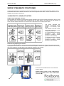
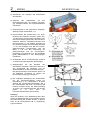
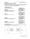
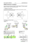
Single-acting diaphragm actuators
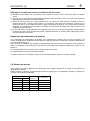
Check whether the actuator is in the safety position required by the process. (Does the actuator open or close
with spring force?) The mounting side is selected from the table below in accordance with the direction of
action and the required direction of movement of the spindle for an increasing input signal.
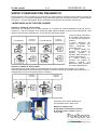
The arrow indicates the
direction of movement of the
spindle at increasing input
signal.
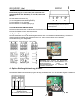
The direction of action of the
input signal can be set on the
changeover plate 13 :
N = Normal direction of action
(increasing
input
signal
produces increasing control
pressure to the actuator)
U = Reverse direction of action
(increasing
input
signal
produces decreasing control
pressure to the actuator)
Double-acting diaphragm actuators
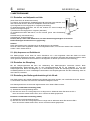
For double-acting positioners the changeover plate 13 always stays in the “N” setting. The assignment of the
input signal to the direction of movement of the actuator spindle is determined by the selection of the mounting
side of the positioner and the piping of the positioner outputs to the actuator:
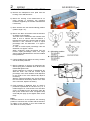
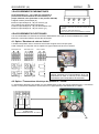
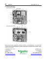
Ensure that the feedback lever 11 is horizontal
at 50 % stroke.
Fasten housing cover in such a way that air
vent of attached device faces downwards
(see Mark ‘M‘).
M
12
11