1
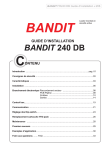
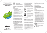
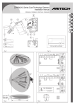
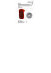
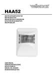
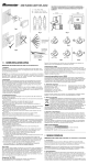
HAA50
INFRARED CEILING-MOUNTED PIR DETECTOR
INFRARODE PIR DETECTOR VOOR PLAFONDMONTAGE
DETECTEUR PIR POUR MONTAGE AU PLAFOND
User Manual
Gebruikershandleiding
Manuel d’utilisation
HAA50 – INFRARED CEILING-MOUNTED PIR DETECTOR
1. Introduction
The HAA50 is a ceiling-mounted PIR detector, designed for use with residential and commercial
security applications. It provides a conical detection pattern. This pattern has a Ø of 36ft (11m)
when the device is mounted on a 12ft- ceiling (3.6m).
The HAA50 is fitted with pulse-counting PIR detection circuitry and employs a pyroelectric
sensor equipped with two elements that produce low-level noise only. These two elements also
provide substantial immunity to false alarm.
2. Detection Pattern
detection LED
pulse counter
selector
LED
on/off
PIR sensor
mounting hole
mounting hole
tamper switch
relay
connection
terminals
wire knockout
3. Mounting Location
•
•
•
•
•
•
Mount the detector on a stable ceiling at a max. height of 12ft (3.6m).
Install the detector in an environment that is shielded from the elements.
Select a mounting location that will allow the beams of the detector to pick up the
movements of possible intruders.
Avoid direct exposure to hot or cold air currents.
The unit should not be aimed at surfaces that are subject to sudden and violent changes in
temperature, such as air conditioning vents, exterior metal walls, windows or the curtains in
front of them, refrigerator or freezer grilles, etc.
Do not place large objects in front of the detector, as this will diminish the area covered by
the detector's beams.
HAA50
1
VELLEMAN
4. Mounting
•
•
•
Open the cover by gently inserting a small screwdriver in the slot between the two halves of
the unit.
Mount the base of the unit at the selected location. Use the two mounting holes to fasten the
unit to the ceiling.
Use the wire knockout at the back of the base to run the wire.
5. Wiring
Connect the wires to the terminal block in the following order :
1) Connect the TAMPER terminals to a normally closed (N.C.)
24h-protection zone of the alarm control panel. The tamper
contact will open when the cover is removed.
2) Connect the ALARM terminals to a normally closed (N.C.)
anti-intrusion zone of the alarm control panel. The relay
contact will open when motion is detected or in the event of
power loss.
3) Connect the 12VDC (+) and (-) terminals to a power source of
8 to 16VDC. Observe the polarity. The buyer is advised to
use a back-up battery.
alarm
12V
tamper
6. Pulse Counter Selector
The user can choose between single-pulse or double-pulse
detection.
v Put the pulse jumper in position "1" for single-pulse detection.
v Put the pulse jumper in position "2" for double-pulse detection.
Double-pulse detection further improves the system’s immunity
against false alarm.
pulses
NOTE : The unit is supplied with the pulse jumper in position "2".
7. Detection LED
1) Use a power source of 12VDC and allow 3 to 5 minutes for the unit to warm up and stabilise
before testing.
2) Walk across the protected area at 1 step per second and observe the LED. If the detector is
in single-pulse mode, the LED will light up whenever you enter or exit one of the protection
beams. If the detector is in double-pulse mode, you may have to take two steps in order to
trigger the detector and activate the LED.
8. LED on/off
After testing the device, the LED can be disabled in order to
prevent unauthorised persons from tracing the coverage pattern.
Put the LED jumper in the "OFF" position to disable the LED.
HAA50
2
VELLEMAN
9. Specifications
Detection Pattern
Operating Voltage
Quiescent Current
Relay Output
Activation Delay
Alarm Output
Tamper Output
LED
Pulse Counter
Mounting Height
: conical pattern, 360°. Detection area with a Ø of 36ft (11m) if the
detector is attached to a 12ft-ceiling (3.6m).
: 8-16VDC
: 15mA nominal at 12VDC
: N.C. (Normally Closed)
: 2 to 3 seconds
: N.C. (fail-safe) dry relay contact of 0.5A / 24VDC, 18Ω-resistor
connected in series with the contact
: N.C. dry contact (Normally Closed) of 0.5A / 24VDC
: indicates detection, can be switched off
: single- or double-pulse detection, detection through alternating polarity
of the signal
: max. 12ft (3.6m)
All specifications are subject to modification without prior notice.
HAA50 – INFRARODE PIR DETECTOR VOOR PLAFONDMONTAGE
1. Inleiding
PIR-detector voor plafondmontage, speciaal ontworpen voor commerciële en residentiële
beveiligingssystemen. De HAA50 gebruikt een kegelvormig detectiepatroon. Dat patroon heeft
een Ø van 11m indien de detector is bevestigd aan een plafond van 3.6m hoog.
De HAA50 maakt gebruik van een PIR detectieschakeling met pulsteller en is uitgerust met een
pyro-elektrische sensor met twee elementen die weinig ruis produceren. Dank zij deze
elementen worden de meeste valse alarmmeldingen vermeden.
2. Detectiepatroon
detectie LED
jumper voor
pulsteller
LED
aan/uit
PIR sensor
montageopening
montageopening
tamper schakelaar
relais
aansluitklemmen
kabeluitsparing
HAA50
3
VELLEMAN
3. Montageplaats
•
•
•
•
•
•
Bevestig de detector aan een stabiel plafond op een max. hoogte van 3.6m.
Installeer de detector in een omgeving die beschermd is tegen de elementen.
Monteer de detector op een plaats van waaruit de stralen elke beweging van mogelijke
indringers kunnen detecteren.
Vermijd rechtstreekse blootstelling aan koude of warme luchtstromen.
Richt de detector niet op oppervlakken of plaatsen die onderhevig zijn aan plotse en hevige
temperatuurswijzigingen, zoals bv. air conditioning installaties, metalen buitenmuren,
vensters of de gordijnen voor deze vensters, roosters van koelkasten en diepvriezers, enz.
Plaats geen grote voorwerpen voor de detector : ze beperken het detectiegebied.
4. Montage
•
•
•
Open de behuizing voorzichtig : stop een schroevendraaier in de gleuf tussen de twee
helften van het toestel.
Gebruik de twee montageopeningen om de basis van de detector op de gekozen plaats aan
het plafond te bevestigen.
Gebruik de kabeluitsparing aan de achterkant van de basis voor de bedrading.
5. Bedrading
Verbind de kabels met de aansluitklemmen in deze volgorde :
1) Verbind de TAMPER aansluitingen met een normaal gesloten
(N.C.) 24u beschermde zone van het controlepaneel van uw
alarm. Het tampercontact gaat open wanneer de behuizing
wordt geopend.
2) Verbind de ALARMaansluitingen met een normaal gesloten
(N.C.) anti-inbraak zone van het controlepaneel van uw
alarm. Het relaiscontact gaat open in geval van stroomverlies
of wanneer beweging wordt gedetecteerd.
3) Verbind de (+) en (-) aansluitingen van 12VDC met een
voedingsbron van 8 tot 16VDC. Respecteer de polariteit. We
raden u aan om een back-up batterij te voorzien.
alarm
12V
tamper
6. Jumper voor pulsteller : 1 of 2 pulsen
U kunt enkelvoudige-puls detectie of dubbele-puls detectie
instellen.
v Plaats de puls jumper op "1" voor enkelvoudige-puls detectie.
v Plaats de puls jumper op "2" voor dubbele-puls detectie.
Dubbele-puls detectie biedt ook extra bescherming tegen valse
alarmmeldingen.
pulsen
OPMERKING : De HAA50 wordt geleverd met de puls jumper in
positie "2".
HAA50
4
VELLEMAN
7. Detectie LED
1) Gebruik een voedingsbron van 12VDC en wacht 3 tot 5 minuten tot het toestel is
opgewarmd en gestabiliseerd voor u het begint te testen.
2) Wandel door het detectiegebied met een snelheid van 1 stap per seconde en kijk naar de
LED. Bij de enkelvoudige-puls mode licht de LED op telkens u de binnen- of buitenrand van
een straal raakt. Bij de dubbele-puls mode is het mogelijk dat u twee stappen moet nemen
om de detector te doen afgaan en de LED te activeren.
8. Led aan/uit
Nadat u het toestel heeft getest, kunt u de LED uitschakelen om
te beletten dat onbevoegde personen het detectiepatroon van
het toestel zouden leren kennen. Plaats de LED jumper in de
"OFF"-stand om de LED uit te schakelen.
9. Specificaties
Detectiepatroon
: kegelvormig patroon, 360°. Detectiegebied met een Ø van 11m
wanneer de detector is bevestigd aan een plafond van 3.6m hoog.
Bedieningsspanning : 8-16VDC
Ruststroom
: 15mA nominaal bij 12VDC
Relaisuitgang
: N.C. (Normaal Gesloten)
Instelvertaging Alarm : 2 à 3 seconden
Alarmuitgang
: N.C. droog relaiscontact (bedrijfszeker) van 0.5A / 24VDC, weerstand
van 18Ω in serie geschakeld met het contact
Tamperuitgang
: N.C. contact (Normaal Gesloten) van 0.5A / 24VDC
LED
: geeft indicatie van detectie en kan worden uitgeschakeld
Pulsteller
: keuze tussen enkelvoudige-puls of dubbele-puls detectie, detectie via
wisselende polariteit van het signaal
Montagehoogte
: max. 3.6m
De specificaties kunnen te allen tijde worden aangepast zonder voorafgaande kennisgeving.
HAA50 – DETECTEUR PIR POUR MONTAGE AU PLAFOND
1. Introduction
Détecteur PIR pour montage au plafond, conçu pour des systèmes de sécurité utilisés dans un
environnement domestique ou commercial. Le HAA50 utilise une zone de détection conique.
Cette zone a un Ø de 11m si le détecteur est attaché à un plafond d'une hauteur de 3.6m.
Le HAA50 emploie un circuit de détection PIR avec compteur d'impulsions et il est équipé d'un
capteur pyroélectrique à deux éléments qui ne produisent qu'un bruissement quasi inaudible.
Ces éléments permettent d'éviter la plupart des alertes intempestives.
HAA50
5
VELLEMAN
2. Mode de détection
cavalier pour
compteur
d’impulsions
LED
on/off
LED de
détection
capteur PIR
trou
trou
commutateur antisabotage (tamper)
relais
évidement
du câble
bornes de
connexion
3. Lieu de montage
•
•
•
•
•
•
Attachez le détecteur à un plafond stable d'une hauteur max. de 3.6m.
Installez le détecteur dans un environnement protégé contre les éléments.
Installez le détecteur à un endroit qui permet aux rayons de l'appareil de détecter chaque
mouvement d'un cambrioleur éventuel.
Evitez toute exposition aux courants d'air chauds ou froids.
Le détecteur ne peut pas être orienté vers des surfaces ou des endroits qui sont sujets à
des changements de température soudains et violents comme, par exemple, les
climatiseurs, des murs extérieurs métalliques, des fenêtres ou leurs rideaux, des grilles de
réfrigérateurs ou de congélateurs, etc.
Déplacez tout objet large qui pourrait diminuer la zone protégée en gênant les rayons.
4. Montage
•
•
•
Ouvrez le boîtier prudemment : insérez un tournevis dans la fente entre les deux parties de
l'appareil.
Fixez l'appareil au plafond à l'endroit choisi au moyen des deux trous.
Utilisez l'évidement du câble au dos de la partie inférieure de l'appareil pour le câblage.
5. Câblage
Connectez les câbles aux bornes de connexion dans l'ordre
suivante :
1) Connectez les connexions TAMPER (anti-sabotage) à une
zone 24h N.C. (normalement fermé) du panneau de
commande de votre alarme.
2) Connectez les connexions d'ALARME à une zone antiintrusion N.C. (normalement fermé) du panneau de commande
HAA50
6
alarme 12V
tamper
VELLEMAN
de votre alarme. Le contact relais s’ouvre en cas de perte de
courant ou lorsque le HAA50 détecte du mouvement.
3) Branchez les connexions (+) et (-) de 12VCC à une source
d'alimentation de 8 à 16VCC. Respectez la polarité. Nous
vous conseillons de prévoir une batterie de sauvegarde.
6. Compteur d'impulsions (cavalier)
Le détecteur s'utilise avec détection à simple ou double impulsion.
v Mettez le cavalier du compteur d'impulsions dans la position
"1" pour détection à simple impulsion.
v Mettez le cavalier du compteur d'impulsions dans la position
"2" pour détection à double impulsion.
impulsions
REMARQUE : Le HAA50 est livré avec le cavalier du compteur
d'impulsions dans la position "2".
7. LED de détection
1) Employez une source d'alimentation de 12VCC. Attendez 3 à 5 minutes pour laisser le
temps à l'appareil de stabiliser et de chauffer.
2) Promenez-vous dans la zone de détection à une vitesse d'un pas par seconde et regardez
la LED. Si le détecteur est en mode de détection à simple impulsion, la LED s'allumera
chaque fois que vous touchez le bord intérieur ou extérieur d'un des rayons. Si le détecteur
est en mode de détection à double impulsion, il est possible qu'il faudra faire deux pas afin
d'activer le détecteur et d'allumer la LED.
8. LED on/off
Après avoir testé l'appareil, vous pouvez désactiver la LED pour
empêcher aux personnes non autorisées d'apprendre la position
des rayons. Mettez le cavalier de la LED dans la position "OFF"
afin de désactiver la LED.
9. Spécifications
Mode de détection
: diffusion conique des rayons (360°). Ø de la zone de détection :
11m si le détecteur est fixé à un plafond d'une hauteur de 3.6m.
Tension d'opération
: 8-16VCC
Courant permanent
: 15mA nominal à 12VCC
Sortie relais
: N.F. (Normalement Fermé)
Temporisation de déclenchement : 2 à 3 secondes
Sortie alarme
: contact relais sec N.F. (fiable) de 0.5A / 24VCC,
résistance de 18Ω connectée en série avec le contact
Sortie anti-sabotage
: contact N.F. (Normalement Fermé) de 0.5A / 24VCC
LED
: s'allume en cas de détection, peut être déconnectée
Compteur d'impulsions
: détection à simple ou à double impulsion, détection via la
polarité alternante du signal
Hauteur de fixation
: max. 3.6m
Les spécifications peuvent être modifiées sans avis préalable.
HAA50
7
VELLEMAN