1
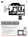
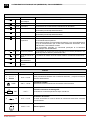
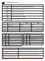
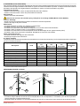
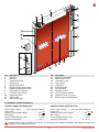
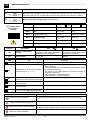
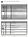
49E
5.1 49E ELECTRONIC CONTROL PANEL - Connections
INPUTS
Command
Function
Description
1
2
N.O Automatic closing
Permanently closing the contact enables automatic closing.
1
3
N.O Opening
With DIP1=ON the closure of the contact activates an opening operation.
Step-by-step
With DIP1=OFF the closure of the contact activates an opening or closing
operation in the following sequence: open-stop-close-open.
Note: if automatic closing is enabled, the stop is not permanent but at a
time that is set by the TC.
1
4
N.O Closing
The closing manoeuvre starts when the contact is closed.
1
6
N.C Reversal safety
device
Opening the safety contact triggers a reversal of the movement (reopening)
during a closing operation.
41
8
N.C Reversal safety
device
Opening the safety contact triggers a reversal of the movement (reopening)
during a closing operation.
1
9
N.C Stop
Opening the safety contact stops the current operation.
1
9
N.O Non-pulse command Permanently opening the safety contact enables the operation by nonpulse command.
In this state, the opening (1-3/1-20) and closing (1-4) controls function only
if held in the pressed position, and the automation stops when the controls
are released.
All safety switches, the step-by-step control and the automatic closing
function are disabled.
1
20
N.O Partial opening
The closing of the contact activates a partial opening operation of the
duration set with the RP trimmer.
Once the automation stops, the partial opening control performs the
opposite operation to the one performed before stoppage.
0
11
N.C Closure limit switch
The opening of the limit switch contact stops the closure operation.
0
12
N.C Opening limit switch
The opening of the limit switch contact stops the opening operation.
0
17
N.O limit switch photocell By-pass photocell
Operation by non-pulse command
Operation by pulse command
17 14 12 11 0 0 0 1 1 2 3 4 6 8 9 20 41
17 14 12 11 0 0 0 1 1 2 3 4 6 8 9 20 41
OUTPUTS
Output
Value
Description
1
0
+
–
24 V = / 0,5 A
Accessories power supply.
Power supply output for external accessories, including automation status
lamp.
0
14
24 V = / 50 W
(2 A)
Flashing light (LAMPH).
Activated during opening and closing operations.
24 V = / 0,5 A
Output activated during the door running.
400 V~ / 4 A
Three-phase motor.
Note: if the direction of rotation of the motor is incorrect for the desired direction
of movement, swap the U - W phases.
- LK +
UWV
M
3~
0DT848 2015-05-27
- 30 -