1
www.axemotion.com
Axemotion Copyright 2007
16
4 ANNEXES
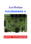
4.1 Description des connecteurs
CN1
INPUT
Pin
1
Function
Input 1
2
3
Input 2
Input 3
4
Input 4
5
Input 5
6
Input 6
7
Input 7
8
Input 8
9
Gnd
CN2
Pin
1
2
3
4
5
6
7
8
9
I/O
Function
Gnd
Output 1
Output 2
Output 3
Output 4
Input 9
Input 10
Input 11
Input 12
X1 USB Type B
CN3
Pin
1
2
3
Ouput
Function
GND
PWM
Relay
CN4 AxMoBus
CN5 Analog Output
Pin Function
1
Gnd
CN6
Pin
1
2
3
4
USB Ext
Function
Gnd
D+
DUSB Vcc
CN7
Pin
1
2
Relay Contact
Function
Contact 1
Contact 2
CN8
Pin
1
2
POWER
Function
PWR PWR+
CN9
1
2
3
4
Motor Z
A
A’
B
B’
CN10
1
2
3
4
CN11
1
2
3
4
Motor Y
A
A’
B
B’
Motor X
A
A’
B
B’