1
Montage- und Anschlussanleitung / AS-i Sicherheitsmonitor
Mounting and wiring Instructions / AS-i Safety Monitor
Instructions de montage et de câblage / Moniteur de sécurité AS-i
ASM E1-R2
ASM E2-R2/R2
1/6
deutsch
Bestimmung und Gebrauch
Der AS-i Sicherheitsmonitor erlaubt bei bestimmungsgemäßer Verwendung den Betrieb von sensorgesteuerten Personenschutzeinrichtungen und weiteren Sicherheitsbauteilen bis einschließlich
Kategorie 4 nach EN 954-1. Werden Sensoren niedrigerer Kategorien angeschlossen, so bestimmt sich die maximal zu erreichende
Kategorie für den entsprechenden Sicherheitspfad nach diesen
Sensoren.
Mounting, commissioning and maintenance of the device may only
be carried out by qualified personnel. Work on electrical installations
may only be carried out by qualified electricians. Settings and changes of the device configuration via PC and asimon configuration
software must only be performed by an authorised safety officer.
The password for changing a device configuration is to be held
under lock and key by the safety officer.
Repairs, in particular the opening of the housing, may only be carried out by the manufacturer or a person authorised by the manufacturer.
Der Sicherheitsmonitor übernimmt auch die für alle nicht handgeführten Maschinen obligatorische NOT-AUS Funktion (Stop-Kategorie 0 oder 1), die dynamische Überwachung der WiederanlaufFunktion und die Schützkontroll-Funktion.
Hinweis
Alle Angaben dieser Bedienungsanleitung, insbesondere Sicherheitshinweise und Inbetriebnahme müssen unbedingt beachtet
werden. Bewahren Sie diese Bedienungsanleitung sorgfältig auf.
Sie sollte immer verfügbar sein.
Beachten Sie die örtlich geltenden gesetzlichen Bestimmungen und
Vorschriften.
Die Montage, Inbetriebnahme und Wartung der Geräte darf nur von
qualifiziertem Fachpersonal durchgeführt werden. Elektrische
Arbeiten dürfen nur von Elektro-Fachkräften durchgeführt werden.
Die Einstellung und Änderung der Gerätekonfiguration per PC und
Konfigurationssoftware asimon darf nur von einem dazu autorisierten
Sicherheitsbeauftragten vorgenommen werden. Das Passwort zum
Ändern einer Gerätekonfiguration ist vom Sicherheitsbeauftragten
verschlossen aufzubewahren.
Reparaturen, insbesondere das Öffnen des Gehäuses, darf nur vom
Hersteller oder einer vom Hersteller autorisierten Person vorgenommen werden.
english
Destination and use
When used as intended, the AS-i safety monitor allows the operation of sensor-controlled systems for the protection of persons and
other protective components up to and including Category 4 acc. to
EN 954-1. If sensors of lower categories are connected, the maximum category achieved for the given safety path is determined by
these sensors.
The safety monitor also performs the mandatory emergency shutdown function for all non-hand-operated machines (Stop Category 0 or
1), the dynamic monitoring of the restart function and the contactor
control function.
Notice
All entries in this operating manual must be heeded, in particular
Safety Notices and Commissioning. Keep this operating manual
in a safe place. It should be accessible at all times.
Observe the locally applicable legal regulations and rules.
français
Destination et usage
S'il est employé conformément aux directives d'utilisation normale,
le moniteur de sécurité AS-i peut être combiné à des dispositifs de
protection de personnes contrôlés par capteurs et à d'autres
composants de sécurité de catégorie allant jusqu'à 4 inclus selon
EN 954-1. Si vous raccordez des capteurs de catégories inférieures,
alors la catégorie maximale de la boucle de sécurité correspondante
sera celle de ces capteurs.
Le moniteur de sécurité prend également en charge la fonction
d'arrêt d'urgence (catégorie d'arrêt 0 ou 1) obligatoire pour toutes
les machines non manuelles, ainsi que la surveillance dynamique de
la fonction de redémarrage et la fonction de contrôle à contacteurs.
Remarque
Toutes les indications contenues dans ce manuel d’utilisation, et en
particulier Recommandations de sécurité et Mise en service doivent
absolument être respectées. Conservez ce manuel d'utilisation avec
soin. Il doit toujours être disponible.
Respectez les décrets et les règlements en vigueur dans la région.
Le montage, la mise en service et la maintenance des appareils doivent toujours être effectués par des experts qualifiés. Les travaux
électriques ne doivent être effectués que par des personnes qualifiées en électrotechnique. La définition et la modification de la configuration de l'appareil avec un ordinateur et le programme de configuration asimon doivent être réalisées uniquement par les personnes autorisées. Le responsable de la sécurité doit conserver le mot
de passe permettant de changer la configuration de l'appareil dans
un endroit fermé.
Les réparations, en particulier l'ouverture de l'appareil, doivent
être réalisées par le fabricant ou une personne autorisée par lui
uniquement.
Montage- und Anschlussanleitung / AS-i Sicherheitsmonitor
Mounting and wiring Instructions / AS-i Safety Monitor
Instructions de montage et de câblage / Moniteur de sécurité AS-i
ASM E1-R2
ASM E2-R2/R2
2/6
deutsch
Montage
Die Montage des AS-i-Sicherheitsmonitors erfolgt auf 35 mm Normschienen nach DIN EN 50022 im Schaltschrank.
Montage
Mounting
Montage
Montagezubehör
Da es sich bei dem AS-i-Sicherheitsmonitor um ein Sicherheitsbauteil handelt, besteht die Möglichkeit den unbefugten Zugriff auf
die Konfigurationsschnittstelle CONFIG und den Taster Service
durch Verplombung zu schützen. Im Lieferumfang des Gerätes finden Sie dazu eine Klarsichtabdeckung mit Sicherungshäkchen,
durch die Sie im montierten Zustand einen Plombendraht bzw.
-faden ziehen können.
D
C
A
Hinweis
Die Klarsichtabdeckung mit Sicherungshäkchen sollten Sie in jedem
Fall anbringen, da sie einen guten Schutz gegen Elektrostatische
Entladungen (ESD) und das Eindringen von Fremdkörpern in die
RJ45-Buchse CONFIG der Konfigurationsschnittstelle des AS-iSicherheitsmonitors bietet.
english
A, B, C, D kodiert
coded
codé
Mounting
The AS-i safety monitor is mounted on 35 mm standard rails acc.
to DIN EN 50022 in the switching cabinet.
Mounting accessories
As the AS-i safety monitor is a safety component, it is possible to
protect the device from unauthorised access by sealing the CONFIG
configuration interface and the Service button. Included in the delivery contents for the device is a transparent cover with safety hook
through which you can pass a lead sealing wire or thread when the
device is in its mounted state.
Notice
The transparent cover with safety hook should always be used as
they provide good protection against electrostatic discharges (ESD)
and the penetration of foreign bodies into the CONFIG RJ45 socket
of the AS-i safety monitor configuration interface.
français
B
b
c
a
Montage
Le moniteur de sécurité AS-i est monté dans l'armoire de commande sur des rails 35 mm standard conformément à la norme
DIN EN 50022.
Accessoires pour le montage
Comme le moniteur de sécurité AS-i est un composant de sécurité,
il est possible de protéger l'accès à l'interface de configuration
CONFIG et à la touche Maintenance par un plombage. Vous trouverez pour cela dans le contenu de la livraison un couvercle transparent avec des crochets de sécurité qui permettent de faire passer un
fil de plombage tout en laissant l'appareil monté.
Remarque
Nous vous recommandons de toujours mettre le couvercle transparent avec les crochets de sécurité en place : il apporte une bonne
protection contre les décharges électrostatiques (ESD) et empêche
la pénétration de corps étrangers dans la prise RJ45 CONFIG de
l'interface de configuration du moniteur de sécurité AS-i.
U=0V
d
Verplombung
Sealing
Plombage
ASM E1-R2
ASM E2-R2/R2
Montage- und Anschlussanleitung / AS-i Sicherheitsmonitor
Mounting and wiring Instructions / AS-i Safety Monitor
Instructions de montage et de câblage / Moniteur de sécurité AS-i
3/6
deutsch
english
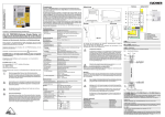
Klemmenbelegung AS-i-Sicherheitsmonitor Typ 1/2
Klemme
Signal / Beschreibung
AS-i+
Anschluss an den AS-i-Bus
AS-i–
Anschluss an den AS-i-Bus
L+
+24 V DC / Versorgungsspannung
M
GND / Bezugserde
FE
Funktionserde
1.Y1
EDM 1 / Eingang Schützkontrolle Kanal 1
1.Y2
Start 1 / Start-Eingang Kanal 1
1.13 / 1.14
Freigabepfad 1 Kanal 1
1.23 / 1.24
Freigabepfad 2 Kanal 1
1.32
Meldeausgang 1 "Safety on" Kanal 1
2.Y1
EDM 2 / Eingang Schützkontrolle Kanal 2
2.Y2
Start 2 / Start-Eingang Kanal 2
2.13 / 2.14
Freigabepfad 1 Kanal 2
2.23 / 2.24
Freigabepfad 2 Kanal 2
2.32
Meldeausgang 2 "Safety on" Kanal 2
Terminal assignment AS-i safety monitor type 1/2
Termi nal
Signal / description
AS-i+
Connection at the AS-i bus
AS-i–
Connection at the AS-i bus
L+
+24 V DC / supply voltage
M
GND / reference ground
FE
Functional earth
1.Y1
EDM 1 / contactor monitoring input, channel 1
1.Y2
Start 1 / start input, channel 1
1.13 / 1.14
Enabling path 1, channel 1
1.23 / 1.24
Enabling path 2, channel 1
1.32
Message output 1 "Safety on" channel 1
2.Y1
EDM 2 / contactor monitoring input, channel 2
2.Y2
Start 2 / start input, channel 2
2.13 / 2.14
Enabling path 1, channel 2
2.23 / 2.24
Enabling path 2, channel 2
2.32
Message output 2 "Safety on", channel 2
Klemmenbelegung
Terminal
assignment
Affectation
des bornes
1.13 1.23 1.Y1
AS-i+ AS-i- 1.Y2
www.schmersal.com
C
ASM E1-R2
AS-i
Service
1
2
3
1 READY
2 ON
3 OFF/FAULT
CONFIG
L+ M 1.32
1.14 1.24 FE
ASM E1-R2
1.13 1.23 1.Y1 2.13 2.23 2.Y1
AS-i+ AS-i- 1.Y2
2.Y2
www.schmersal.com
français
Affectation des bornes du moniteur de sécurité AS-i de type 1/2
Borne
Signal / description
AS-i+
Raccordement au bus AS-i
AS-i–
Raccordement au bus AS-i
L+
+24 V CC / tension d'alimentation
M
GND / terre de référence
FE
Terre de fonction
1.Y1
EDM 1 / Entrée "contrôle à contacteurs" voie 1
1.Y2
Démarrage 1 / Entrée démarrage voie 1
1.13 / 1.14
Sortie de sécurité 1 voie 1
1.23 / 1.24
Sortie de sécurité 2 voie 1
1.32
Sortie de signalisation 1 "Safety on" voie 1
2.Y1
EDM 2 / Entrée "contrôle à contacteurs" voie 2
2.Y2
Démarrage 2 / Entrée démarrage voie 2
2.13 / 2.14
Sortie de sécurité 1 voie 2
2.23 / 2.24
Sortie de sécurité 2 voie 2
2.32
Sortie de signalisation 2 "Safety on" voie 2
C
AS-i
ASM E2-R2/R2
Service
1
2
3
1
2
3
1 READY
2 ON
3 OFF/FAULT
CONFIG
L+
M 1.32
1.14 1.24 FE 2.14 2.24
ASM E2-R2/R2
2.32
ASM E1-R2
ASM E2-R2/R2
Montage- und Anschlussanleitung / AS-i Sicherheitsmonitor
Mounting and wiring Instructions / AS-i Safety Monitor
Instructions de montage et de câblage / Moniteur de sécurité AS-i
4/6
L/+
Anschlussbeispiel
Wiring example
Exemple de raccordement
L/+
M
L
S2
S1
AS-iAS-i+
M1
AS-i+ AS-i-
1Y1
AS-i
Interface
1Y2
2Y1
1.32
2Y2
M2
2.32
1.13
1.23
2.13
2.23
1.14
1.24
2.14
2.24
K1
RJ 45
K3
RS
232
K2
K4
24 V
L+
M
FE
2.14
2.24
L1 L2 L3
K5
L/+
3
AS-i-Busanschluss
AS-i bus connection
Raccordement du
bus AS-i
2-adriges AS-i-Rundkabel
(empfohlen: flexible Starkstromleitung H05VV-F2x1,5 nach DIN VDE 0281)
Two-conductor AS-i round cable
(recommended: flexible power cable H05VV-F2x1.5 acc. to DIN VDE 0281)
Câble rond AS-i à deux fils
(recommandation : ligne courant fort flexible H05VV-F2x1,5 conforme à DIN VDE 0281)
Legende
Legend
Légende
AS-i–
Blau
Blue
Bleu
AS-i+
Braun
Brown
Marron
M
K7
K8
K6
M/N
Gelbes AS-i-Flachkabel
Yellow AS-i ribbon cable
Câble plat AS-i jaune
K7
K5
K6
M
L1 L2 L3
M/N
K8
3
M
ASM E1-R2
ASM E2-R2/R2
Montage- und Anschlussanleitung / AS-i Sicherheitsmonitor
Mounting and wiring Instructions / AS-i Safety Monitor
Instructions de montage et de câblage / Moniteur de sécurité AS-i
5/6
deutsch
Bedeutung der LED-Anzeigen im Schutzbetrieb
Die LED-Anzeigen an der Frontseite des AS-i-Sicherheitsmonitors geben Ihnen Aufschluss über die Betriebsart und den Gerätezustand.
LED
AS-i 1
AS-i 2
1 READY
(je Kanal)
2 ON
(je Kanal)
3 OFF/FAULT
(je Kanal)
1 READY
2 ON
3 OFF/FAULT
(je Kanal)
english
Farbe
grün, aus
Bedeutung
Keine Versorgung
grün, dauerleuchtend
AS-i-Versorgung vorhanden
rot, aus
Normaler Betrieb
rot, dauerleuchtend
Kommunikationsfehler
gelb, aus
–
gelb, dauerleuchtend
Anlauf-/Wiederanlaufsperre aktiv
gelb, blinkend
externer Test erforderlich
grün, aus
Kontakte des Ausgangsschaltelements offen
grün, dauerleuchtend
Kontakte des Ausgangsschaltelements geschlossen
grün, blinkend
Verzögerungszeit läuft bei Stoppkategorie 1
rot, aus
Kontakte des Ausgangsschaltelements geschlossen
rot, dauerleuchtend
Kontakte des Ausgangsschaltelements offen
rot, blinkend
Fehler auf Ebene der überwachten AS-i-Komponenten
alle gleichzeitig
schnell blinkend
Interner Gerätefehler
nicht belegt
LED AS-i 1
LED AS-i 2
Kanal 1
Kanal 2
Meanings of the LED indicators in protective operation
The LED indicators on the front side of the AS-i safety monitor provide information about the operating mode and the device state.
LED
AS-i 1
AS-i 2
1 READY
(per channel)
2 ON
(per channel)
3 OFF/FAULT
(per channel)
1 READY
2 ON
3 OFF/FAULT
(per channel)
Colour
green, off
Meaning
no supply
green, continuous
AS-i supply present
red, off
normal operation
red, continuous
communication error
yellow, off
–
yellow, continuous
startup/restart-disable active
yellow, flashing
external test required
green, off
contacts of the output switching element open
green, continuous
contacts of the output switching element closed
green, flashing
delay time runs in event of Stop Category 1
red, off
contacts of the output switching element closed
red, continuous
contacts of the output switching element open
red, flashing
error on level of the monitored AS-i components
all simultaneously
flash rapidly
internal device error
not used
LED AS-i 1
LED AS-i 2
Channel
1
Channel
2
ASM E1-R2
ASM E2-R2/R2
Montage- und Anschlussanleitung / AS-i Sicherheitsmonitor
Mounting and wiring Instructions / AS-i Safety Monitor
Instructions de montage et de câblage / Moniteur de sécurité AS-i
6/6
français
Signification de l'affichage à DEL en mode protection
Les affichages à DEL à l'avant du moniteur de sécurité AS-i vous renseigneront sur le mode de fonctionnement et l'état de l'appareil.
LED
AS-i 1
AS-i 2
1 READY
(pour chaque voie)
2 ON
(pour chaque voie)
3 OFF/FAULT
(pour chaque voie)
KAS / 06.2008 / Ident-Nr. 5125181900 / Ausgabe D
1 READY
2 ON
3 OFF/FAULT
(pour chaque voie)
Couleur
vert, éteinte
Signification
Pas d'alimentation
vert, lumière continue
Alimentation AS-i présente
rouge, éteinte
Fonctionnement normal
rouge, lumière continue
Erreur de communication
jaune, éteinte
–
jaune, lumière continue
Blocage au démarrage/redémarrage actif
jaune, clignotante
Test externe requis
vert, éteinte
Contacts de l'élément de commutation de sortie ouverts
vert, lumière continue
Contacts de l'élément de commutation de sortie fermés
vert, clignotante
Temps de retard en cours si catégorie d'arrêt 1
rouge, éteinte
Contacts de l'élément de commutation de sortie fermés
rouge, lumière continue
Contacts de l'élément de commutation de sortie ouverts
rouge, clignotante
Anomalie au niveau des composants AS-i sous contrôle
clignotant rapidement
simultanément
Erreur interne de l'appareil
K. A. Schmersal GmbH
Industrielle Sicherheitsschaltsysteme
Möddinghofe 30, D - 42279 Wuppertal
Postfach 24 02 63, D - 42232 Wuppertal
Telefon
Telefax
E-Mail:
Internet:
+49 - (0)2 02 - 64 74 - 0
+49 - (0)2 02 - 64 74 - 1 00
[email protected]
http://www.schmersal.com
non occupé
LED AS-i 1
LED AS-i 2
voie 1
voie 2