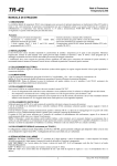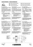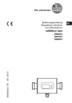
1
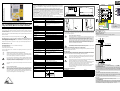
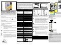
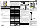
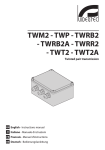
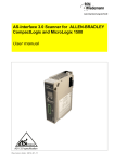
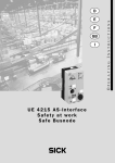
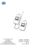
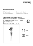
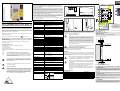
Einsatzbereich
AS-i 3.0 PROFIBUS-Gateway Single Master mit
integriertem Sicherheitsmonitor für 2 AS-i-Kreise
Hinweise zur Benutzung der Anschluss- und Betriebsanleitung
(Draufsicht)
[3]
[4]
[5]
[3]
100
120
Montage
Baudraten
9,6 KBaud bis 12000 KBaud, Autoerkennung
+ASI 1–
DP-Funktionen
Abbildung der AS-i-Slaves als E/A-Prozessdaten im
PROFIBUS
vollständige Diagnose und Konfiguration über
PROFIBUS DP-Master
+ASI 1–
RS 232
AS-i-Zykluszeit
150 μs * (Anzahl Slaves + 2)
4-kanalig
Einschaltverzögerung
< 10 s
EDM: Eingänge der externen Geräteüberwachungskreise
Start: Starteingänge
Sicherheits- und Warnhinweise sind mit dem Symbol
Ausgänge:
4 x Ausgangsschaltelemente
Relais-Ausgänge (Ausgangskreise 1 und 2)
Kartensteckplatz
Chipkarte zur Speicherung von Konfigurationsdaten
LCD
AS-i-Slave-Adressenanzeige, Fehlermeldungen
LED power
Spannung EIN
LED PROFIBUS
PROFIBUS-Master erkannt
EUCHNER GmbH + Co. KG
LED config error
Konfigurationsfehler
LED U AS-i
AS-i-Spannung OK
LED AS-i active
AS-i-Betrieb normal
LED prg enable
automatische Slaveprogrammierung möglich
LED prj mode
Projektierungsmodus aktiv
Zustand der Eingänge
der externen Geräteüberwachungskreise
LED aus: offen
LED an: geschlossen
Zustand der Ausgangskreise
LED aus: offen
LED an: geschlossen
Der Besteller hat die Rückverfolgbarkeit der Geräte über die Seriennummer sicherzustellen.
Sicherheitsmonitore erfüllen eine Personenschutzfunktion. Unsachgemäßer Einbau beeinträchtigt die Funktion! Der Hersteller der Maschine/
Anlage, an der das sicherheitsgerichtete System eingesetzt wird, ist verantwortlich für die korrekte und sichere Gesamtfunktion aller einzelnen
Sicherheitskomponenten! Je nach Auswahl der verwendeten Sicherheitsbauteile kann die Einstufung des gesamten Sicherheitssystems
auch in eine niedrigere Sicherheitskategorie erfolgen!
≥ 500 V
Normen
EN 61 000-6-2, EN 61 000-6-4
EN 62 061, SIL3; EN 61 508, SIL3
EN 13 849, Performance-Level e
Gehäuse
Mastergehäuse in Edelstahl
Umgebungstemperatur
Personenschutzfunktion:
Masternetzteil, ca. 300 mA aus dem AS-i-Kreis
Bemessungsbetriebsspannung AS-i-Spannung 30 V DC
Isolationsspannung
Lagertemperatur
0°C … +55°C
-25°C … +85°C
Maße (L / B / H in mm)
120 / 100 / 96
Schutzart nach IEC 60 529
IP20
zulässige Schock- und
Schwingbeanspruchung
gemäß EN 61 131-2
Gewicht
800 g
5 ... 6 mm / PZ2
+ASI 2– / 24 V, 0 V
Anschluss an 2. AS-i-Kreis / 24 V Versorgung optional
Die elektrische Installation ist von eingewiesenem Fachpersonal durchzuführen. Bei der Installation ist darauf zu achten, dass Versorgungsund Signalleitungen und auch die AS-i-Busleitung getrennt von Kraftstromleitungen verlegt sind. Im Schaltschrank ist darauf zu achten, dass
bei Schützen eine entsprechende Funkenlöschung verwendet wird. Bei
Antriebsmotoren und -bremsen ist auf die Installationshinweise in den
entsprechenden Bedienungsanleitungen zu achten. Bitte beachten Sie,
dass die maximale Leitungslänge für die AS-i-Busleitung 100 m beträgt.
Darüber hinausgehende Leitungslängen erfordern den Einsatz geeigneter Leitungsverlängerungen.
Abb. 1: Anschlussbild Gateway
K3
K4
24V_1
0V_2
24V_2
Bedien- und Anzeigeelemente, Konfiguration
Wartung
Die einwandfreie Funktion des AS-i-Sicherheitsmonitors innerhalb des absichernden
Systems, d. h. das sichere Abschalten bei Auslösung eines zugeordneten sicherheitsgerichteten Sensors oder Schalters, ist vom Sicherheitsbeauftragten mindestens jährlich zu kontrollieren.
Dazu ist jeder sicherheitsgerichtete AS-i-Slave mindestens einmal pro
Jahr zu betätigen und das Schaltverhalten durch Beobachtung der Ausgangskreise des AS-i-Sicherheitsmonitors zu kontrollieren.
Abhängig vom für die Gesamtversagenswahrscheinlichkeit gewählten
PFD-Wert ist die maximale Einschaltdauer und die Gesamtbetriebsdauer zu beachten.
Bei Erreichen der maximalen Einschaltdauer (drei, sechs oder zwölf
Monate) ist die ordnungsgemäße Funktion des Sicherheitssystems
durch Anforderung der Abschaltfunktion zu überprüfen.
Bei Erreichen der Gesamtbetriebsdauer (10 Jahre) ist das Gerät vom
Hersteller auf seine ordnungsgemäße Funktion im Herstellerwerk zu
überprüfen.
0,8 Nm
7 LB.IN
10
2
2 x (0,5 .... 1,5) mm
10
2
2 x (0,5 .... 1,5) mm
AWG
ASI 1 +PWR– (max. 8 A)
Versorgungsspannung AS-i-Kreis 1
Fachgerecht installieren:
Zubehör (optional):
Anschluss
Anschluss an 1. AS-i-Kreis
Siehe Handbuch AS-i 3.0 PROFIBUS-Gateway mit integriertem Sicherheitsmonitor
und Handbuch ASIMON Konfigurationssoftware.
Hilfsenergie liegt an
4 x LED EDM/Start
Bemessungsbetriebsstrom
+ASI 1–
Halten Sie die vorgeschriebene Absicherung unbedingt ein, nur so ist
ein sicheres Abschalten im Fehlerfall gewährleistet.
LED AUX
4 x LED Ausgangskreis
[1] - Chipkarte
[2] - RS 232 Anschluss
[3] - LED-Statusanzeige
[4] - PROFIBUS-Anschluss
[5] - LCD-Anzeige
[6] - Tasten für Handbedienung
1.13 0 V 24 V 2.13
2.Y2 + 2.Y1 +
Elektrische Daten
Zum Anschluss und zur Inbetriebnahme des AS-i-Sicherheitsmonitors
gehört die Kenntnis der Anschluss- und Betriebsanleitung sowie des
Benutzerhandbuchs der ASIMON-Konfigurations- und Diagnosesoftware (siehe Zubehör).
Die Montage des AS-i-Gateways mit integriertem Sicherheitsmonitor erfolgt auf
35 mm Normschienen nach DIN EN 50 022.
Setzen Sie das Gerät zur Montage an der Oberkante der Normschiene an und
schnappen Sie es dann an der Unterkante ein.
Halbleiter-Ausgänge (Ausgangskreise 3 und 4)
© Nachdruck und Vervielfältigung, auch auszugsweise, nur mit ausdrücklicher
Genehmigung durch:
Der Sicherheitsmonitor ist als abschaltende Schutzvorrichtung für das
Absichern von Gefahrenbereichen an kraftbetriebenen Arbeitsmitteln
entwickelt worden. Über die Sicherheitsausgänge wird eine Maschine in
den sicheren Zustand versetzt.
-
+
+ASI
2– / 24V, 0V
Anzeige
Bestimmungsgemäßer Gebrauch des Sicherheitsmonitors:
+
1
3
2
Freigabekreis
< 40 ms
Diese Kurzfassung der Anschluss- und Betriebsanleitung ist Bestandteil des Lieferumfangs.
-
+
ASI 1 +PWR– (max. 8A)
[2]
Serielle Schnittstelle
Eingänge:
4 x EDM/Start
Kohlhammerstraße 16 * D-70771 Leinfelden-Echterdingen
Tel. +49(0)711/7597-0
Fax +49(0)711/753316
Internet: http://www.euchner.de
-
5 mm max!
Ansprechverzögerung
EUCHNER GmbH + Co. KG haftet nicht für Schäden, die durch unsachgemäße
Benutzung entstehen. Zur sachgerechten Verwendung gehört auch die Kenntnis dieser Anleitung.
+
M4
gemäß DIN 19 245, Teil 3
Detaillierte Informationen siehe Handbuch AS-i 3.0 PROFIBUS-Gateway mit integriertem Sicherheitsmonitor.
gekennzeichnet.
[2]
[6]
Demontage
Sicherheitsmonitor
Diese Anschluss- und Betriebsanleitung enthält Informationen über den bestimmungsgemäßen und effektiven Einsatz des AS-i 3.0 PROFIBUS-Gateways mit integriertem Sicherheitsmonitor für 2 AS-i-Kreise.
[1]
96
2 x 24 ...12
Safety Monitor
Id.-No.: 104118 - Ausgabedatum: 2008-7-28
Technische Änderungen vorbehalten
Anschluss- und Betriebsanleitung (Kurzfassung)
Safety Monitor
85
[1]
Technische Daten
PROFIBUS-Schnittstelle
Gateway
Maßzeichung
Das AS-i 3.0 PROFIBUS-Gateway mit integriertem Sicherheitsmonitor für 2
AS-i-Kreise ist die Kombination eines Single-Masters und eines Sicherheitsmonitors für 2 AS-i-Kreise.
Die Sicherheitseinheit stellt 4 Eingänge zur Verfügung, die sowohl als EDM-, oder als
START-Eingänge definiert werden können. Es gibt 2 FGK mit Relais- und 2 FGK mit
Halbleiter-Ausgängen. Der Sicherheitsmonitor überwacht die ihm per Konfigurationssoftware ASIMON zugeordneten sicherheitsgerichteten AS-i-Slaves (z. B. NOT-AUSSchalter). Im Fall einer Stopp-Anforderung oder eines Defektes schaltet der AS-i-Sicherheitsmonitor im Schutzbetrieb das System mit einer Reaktionszeit von maximal
40 ms bei System-Vollausbau sicher ab. Es ist dabei möglich, bis zu 62 sicherheitsgerichtete AS-i-Slaves in ein System einzubinden.
Es ist ein Mischbetrieb von AS-i-Standardkomponenten und sicherheitsgerichteten
AS-i-Komponenten möglich. Innerhalb eines AS-i-Systems können mehrere AS-iSicherheitsmonitore eingesetzt werden. Ein sicherheitsgerichteter AS-i-Slave kann
dabei von mehreren AS-i-Sicherheitsmonitoren überwacht werden.
Der AS-i-Sicherheitsmonitor ist für den Einsatz von Sicherheitsanwendungen bis
Kategorie 4/SIL 3 zugelassen.
Beschreibung
Zugfederklemmen
Schraubklemmen
Kabel zur Programmierung mit PC
1 Speicherkarte
10 Speicherkarten
Programmiersoftware
Bezeichnung
ZMO-ZB-KK8-M
ZMO-ZB-AK8-M
ZMO-ZB-PGK
ZMO-ZB-M1
ZMO-ZB-M10
ZMO-ZB-ANWPG-ASIMON3
+ 1.Y1 + 1.Y2
1.14 3.14 4.14 2.14
K1 K3
K4 K2
0V_1
0V_2
K1
K2
Abb. 2: Anschlussbild Sicherheitsmonitor
1.Y1 (EDM 1/Start 1), 2.Y1 (EDM 2/Start 2), 1.Y2 (EDM 3/Start 3),
2.Y2 (EDM 4/Start 4)
Die Eingänge dürfen nicht mit anderen Potenzialen verbunden werden, sondern
nur direkt oder über potenzialfreie Schalter mit + (für EDM/START).
Schaltstrom statisch 4 mA bei 24 V, dynamisch 30 mA bei 24 V (T=100 µs)
3.14, 4.14
Halbleiter-Ausgänge. Max. Kontaktbelastbarkeit: 0,5 A DC-13 bei 30 V
1.14, 2.14; 1.13, 2.13
Potenzialfreie Relaiskontakte. Sicherheitsrelais mit einem Kontaktsatz zur Rücklesung. Max. Kontaktbelastbarkeit: 3 A AC-15 bei 30 V, 3 A DC-13 bei 30 V
0 V, 24 V
Versorgung der Halbleiterausgänge aus separaten 24 V DC
+ (für EDM/Start)
Stromversorgungs-Ausgang, versorgt aus AS-i. Darf nicht mit anderen Potenzialen, sondern darf nur direkt oder über potenzialfreie Schalter mit einem der EDModer Start-Eingänge verbunden werden. Spannung 30 ... 15 VDC.
Application
Id.-No.: 104118 - Issue date: 2008-7-28
Subject to change without prior notice
Gateway
Dimensional drawing
The AS-i 3.0 PROFIBUS Gateway with integrated Safety Monitor for 2 AS-i networks is a combination of a single master with a safety monitor for 2 AS-i networks.
The safety unit provides 4 inputs either for connecting of EDM or Start inputs.
2 OSSDs with relay and 2 OSSDs with semiconductor outputs are available. The safety unit monitors the safe slaves (e.g. Emergency-STOP push-button) which have been
assigned with the configuration software ASIMON. In the case of a stop request or a
failure, the AS-i safety monitor safely switches the system off in protective operation
mode with a maximum response time of 40 ms. It is possible to integrate up to 62 safety related slaves.
Mixed operation of standard components and safe components is possible.
Multiple AS-i safety monitors can be used within an AS-i system. In this way, a safe
slave can be monitored by multiple AS-i safety monitors.
The AS-i safety monitor is approved for safety applications up to Category 4/SIL 3.
Safety Monitor
85
(top view)
[3]
[4]
[1]
96
[5]
[3]
100
120
Assembling
[2]
[6]
Disassembling
Technical data
PROFIBUS interface
AS-i 3.0 PROFIBUS Gateway Single Master with
integrated Safety Monitor for 2 AS-i networks
Notes on using these connecting and operating instructions
This connecting and operating instruction contains information regarding the proper
and effective use of the AS-i 3.0 PROFIBUS-Gateways with integrated Safety Monitor
for 2 AS-i networks.
See the manual AS-i 3.0 PROFIBUS-Gateways with integrated Safety Monitor for detailed information.
Safety precautions and warnings are designated by the symbol
9,6 kBaud up to 12000 kBaud,
automatic recognition
DP functions
imaging of the AS-i slaves as I/O data of the
PROFIBUS
complete diagnosis and configuration via the
PROFIBUS DP
Serial interface
RS 232
AS-i cycle time
150 μs * (number of slaves + 2)
-
+ASI 1–
[1] - Chip card
[2] - RS 232 connection
[3] - LED status indicator
[4] - PROFIBUS connection
[5] - LCD display
[6] - Buttons for manual operation
+ASI 1–
ASI 1 +PWR– (max. 8A)
[2]
1
3
4-channel
< 10 s
Respond delay
< 40 ms
Inputs:
4 x EDM/Start
EDM: contactor monitoring inputs
Start: start inputs
Outputs:
4 x output switching elements
relay outputs (output circuits 1 and 2)
semiconductor outputs (output circuits 3 and 4)
Ensure appropiate installation:
Connection to 2nd AS-i network / 24 V supply optional
Card slot
chip card for storage of configuration data
Electrical installation is to be performed by trained expert personnel. During installation care must be taken that supply and signal leads and also
the AS-i bus cable are laid separately from power cables. In the switchgear cabinet it must be ensured that appropriate spark-quenching
equipment is used with contactors. Where drive motors and brakes are
used, attention must be paid to the installation instructions in the corresponding operating instructions. Please note that the maximum line
length of the AS-i bus cable is 100 m. Cables above that length require
the use of a suitable circuit extension.
Fig. 1: Connection overview gateway
2
LED power
power on
© Reprint and reproduction, in whole or in part, only with the explicit permission of:
LED PROFIBUS
PROFIBUS master recognized
LED config error
configuration error
EUCHNER GmbH + Co. KG
LED U AS-i
AS-i voltage OK
Kohlhammerstraße 16 * D-70771 Leinfelden-Echterdingen
Tel. +49(0)711/7597-0
Fax +49(0)711/753316
Internet: http://www.euchner.de
LED AS-i active
AS-i normal operation active
LED prg enable
automatic address programming enabled
LED prj mode
configuration mode active
LED AUX
auxiliary power ON
4 x LEDs EDM/Start
state of contactor monitoring input/start input
LED off: open
LED on: closed
4 x LEDs output circuit
state of output switching element
LED off: open
LED on: closed
The orderer has to guarantee the traceability of the devices via the serial
number.
+
Start delay
indication of slave addresses
and error messages
For connection and commissioning of the AS-i Safety Monitor the knowledge is assumend of the connecting und operating instructions as well
as operating instructions of ASIMON configuration and diagnostic software (see accessories – ordering information).
-
+
Release circuit
LCD
The AS-i safety monitor has been designed as a disconnecting protective device to safeguard danger areas on power-driven working materials. The safe outputs put a machine in the safe state.
-
5 mm max!
+
+ASI
2– / 24V, 0V
Display
Specified normal operation of the safety monitor:
+
M4
Safety monitor
EUCHNER GmbH + Co. KG is not liable for damage resulting from improper use
of its equipment. Familiarity with these instructions constitutes part of the
knowledge required for proper use.
This short description of the connection and operating instruction is a part of the
scope of delivery.
[1]
The AS-i gateway with integrated safety monitor is mounted on 35 mm standard rails
acc. to DIN EN 50 022.
For assembling, position the device on the upper edge of the standard rail and snap
it onto the bottom edge then.
+ASI 1–
Connection AS-i 1 circuit
ASI 1 +PWR– (max. 8 A)
Supply voltage AS-i circuit 1
+ASI 2– / 24 V, 0 V
24V_2
1.13 0 V 24 V 2.13
2.Y2 + 2.Y1 +
It is essential to adhere to the prescribed fusing; this is the only way of
guaranteeing safe disconnection in the case of a fault.
Control and indicating elements, configuration
See manual AS-i 3.0 PROFIBUS-Gateway with integrated Safety Monitor and manual
ASIMON configuration software.
Maintenance
The proper function of the AS-i safety monitor within the system to be secured,
i.e. the safe shutdown following the triggering of an assigned safe sensor or
switch, is to be checked at least annually by the safety officer.
Electrical data
Operating current
master power supply, approx. 300 mA out of AS-i circuit
Operating voltage
AS-i voltage 30 V DC
Voltage of insulation
This is to be performed by activating each safe AS-i slave at least once
per year and visually inspecting the switching behaviour of the output
circuits of the AS-i safety monitor.
≥ 500 V
Standards
EN 61 000-6-2, EN 61 000-6-4
EN 62 061, SIL3; EN 61 508, SIL3
EN 13 849, performance level e
Housing
AS-i master housing in stainless steel
Ambient operating temperature
K3
K4
24V_1
0V_2
Safety Monitor
Connecting and operating instruction (abridged version)
according to DIN 19 245 Part 3
Baud rates
0°C … +55°C
Storage temperature
-25°C … +85°C
Dimensions (L / B / H in mm)
120 / 100 / 96
When the maximum switch-on time has been reached (three, six or twelve months), the safety system must be checked to ensure that it is
functioning correctly by prompting the shutdown function.
When the total operating time has been reached (10 years), the device
must be checked at the manufacturer's factory to ensure that it is
functioning correctly.
Person protective function:
Protection category IEC 60 529 IP20
Safety monitors fulfill a person protective function. Inappropriate installation puts the function in risk! The manufacturer of the machine/plant at
that one the safety related devices is used is responsible for the correct
and safe total function of all single safety components! Depending on
the choice of safety components to be used the safety system as a whole may also be assigned to a lower safety category.
Tolerable loading referring to
impacts and vibrations
according to EN 61 131-2
Weight
800 g
Accessories (optional):
Connection
5 ... 6 mm / PZ2
0,8 Nm
7 LB.IN
10
2
2 x (0,5 .... 1,5) mm
10
2
2 x (0,5 .... 1,5) mm
AWG
2 x 24 ...12
+ 1.Y1 + 1.Y2
1.14 3.14 4.14 2.14
The maximum switch-on time and total operating time depends on the
PFD value selected for the overall failure probability.
Description
Cage spring terminals
Screw terminal
Cable for programming with PC
1 chip card
10 chip cards
Configuration software
Name
ZMO-ZB-KK8-M
ZMO-ZB-AK-8
ZMO-ZB-PGK
ZMO-ZB-M11
ZMO-ZB-M10
ZMO-ZB-ANWPG-ASIMON3
K1 K3
K4 K2
0V_1
0V_2
K1
K2
Fig. 2: Connection overview safety monitor
1.Y1 (EDM 1/Start 1), 2.Y1 (EDM 2/Start 2), 1.Y2 (EDM 3/Start 3),
2.Y2 (EDM 4/Start 4)
EDM- and start-inputs may not be connected with other potentials, but may only
be connected directly or over potential-free switches with + (for EDM/START).
Switching current static 4 mA at 24 V, dynamic 30 mA at 24 V (T=100 µs).
3.14, 4.14
Semiconductor outputs. Max. contact load: 0,5 A DC-13 at 30 V
1.14, 2.14; 1.13, 2.13
Potential-free relay switches. Safety relay with a switch-set for feedback.
Max. contact load: 3 A AC-15 at 30 V, 3 A DC-13 at 30 V
0 V, 24 V
Supply for semiconductor outputs out of auxiliary 24 V DC
+ (for EDM/Start)
Current supply output, supplied out of AS-i. It must not be connected with other
potenzials, but it may be connected directly or via potential-free switches with the
one of the EDM- or start inputs. Voltage range 30 ... 15 VDC.
Domaines d’application
Id.-No.: 104118 - Édition: 2008-7-28
Sous réserve de modifications techniques
Gateway
Encombrement
La passerelle AS-i avec moniteur de sécurité pour 2 circuits AS-i est la combinaison d’un maître simple et d’un moniteur de sécurité pour 2 circuits AS-i.
L’unité de sécurité dispose de 4 entrées, qui peuvent être définies comme entrées
EDM ou entrées Start. Deux circuits de validation avec sorties contrôle contacteurs et
deux avec sorties sémiconducteur sont disponibles. Le moniteur de sécurité surveille
les esclaves de sécurité qui lui sont affectés (p. ex. arrêt d’urgence) à l’aide du logiciel
de configuration asimon. En cas de demande d’arrêt ou de défaut, le moniteur de sécurité AS-i se met en mode de sécurité et coupe le système avec un temps de réaction
de 40 ms maximum. Jusqu’à 62 esclaves de sécurité AS-i peuvent être raccordés par
faisceau AS-i.
Un fonctionnement mixte de composants AS-i standards et de composants AS-i de
sécurité est possible. Plusieurs moniteurs de sécurité AS-i peuvent être utilisés sur un
même réseau AS-i. Un même esclave de sécurité AS-i peut être surveillé par plusieurs moniteurs de sécurité.
Le moniteur de sécurité AS-i est conçu pour des applications de sécurité allant jusqu’à
la catégorie 4/SIL 3.
Safety Monitor
85
(Vue d’en haut)
[3]
96
[4]
[1]
[5]
100
[2]
120
Montage
Démontage
[6]
Données techniques
Vitesse de transmission
Instructions de raccordement et de service (Version abrégée)
Passerelle AS-i v3.0 PROFIBUS maître simple avec
moniteur de sécurité AS-i pour 2 circuits AS-i
Remarques pour l’utilisation des instructions de raccordement et
de service
Ces instructions de raccordement et de service contiennent des informations sur l’utilisation conforme et effective de la passerelle AS-i v3.0 PROFIBUS avec moniteur de
sécurité pour 2 circuits AS-i.
Pour plus d’informations, voir le manuel d’utilisation de la passerelle AS-i v3.0 PROFIBUS avec moniteur de sécurité AS-i.
Les avertissements sont caractérisés par le symbole suivant
.
Fonctions DP
selon DIN19 245, partie 3
[1]
+
9,6 KBaud jusqu’à 12000 KBaud,
reconnaissance automatique
RS 232
Temps de cycle AS-i
150 μs*(nombre d’esclaves + 2)
2
Retard à l’enclenchement
< 10 s
Temps de réponse
< 40 ms
Entrées:
4 x EDM/Start
EDM: entrées des circuits de contrôle externes
Start: entrées Start
Sorties:
4 x éléments de commutation
sorties relais (circuits de sortie 1 et 2)
Slot de carte mémoire
carte mémoire pour l’enregistrement des données de configuration
L’installation électrique sera effectuée par du personnel qualifié et informé. Lors de l’installation, veiller à poser les câbles d’alimentation et de
signaux ainsi que le câble bus AS-i séparément des câbles d’énergie.
Dans l’armoire technique, prendre soin d’équiper les contacteurs de dispositifs d’antiparasitage. Pour les moteurs et les freins, respecter les indications figurant dans les instructions de services respectives.
Remarque: la longueur maximale du câble AS-i est de 100 m. Pour les
longueurs supérieures, il faudra monter dans la ligne un répéteur AS-i.
LCD
affichage des adresses esclave AS-i et des messages d’erreur
LED power
tension ON
La passerelle AS-i avec moniteur de sécurité intégré est prévue pour un montage sur
rails normalisés (35 mm) selon DIN EN 50 022.
Pour monter l’appareil, l’appuyer fermement contre la partie supérieure du profilé et
le clipser sur la partie inférieure.
Conseils pour l’installation électrique:
LED PROFIBUS
maître PROFIBUS identifié
EUCHNER GmbH + Co. KG
LED config error
erreur de configuration
Kohlhammerstraße 16 * D-70771 Leinfelden-Echterdingen
Tel. +49(0)711/7597-0
Fax +49(0)711/753316
Internet: http://www.euchner.de
LED U AS-i
tension AS-i OK
LED AS-i active
fonctionnement AS-i normal
Eléments de commande et d’affichage, configuration
LED prg enable
configuration automatique des esclaves possible
LED prj mode
mode de configuration actif
Voir à ce propos le manuel de la passerelle AS-i v3.0 avec moniteur de sécurité intégré et le manuel complet du logiciel de configuration asimon.
LED AUX
énergie auxiliaire présente
4 x LED EDM/Start
état des entrées des circuits de contrôle des
appareils externes
LED off: ouvert / LED on:fermé
4 x LED circuit de sortie
état des circuits de sorties
Cette version abrégée des instructions de raccordement et de service est incluse
dans la livraison.
Utilisation conforme du moniteur de sécurité:
Le moniteur de sécurité est un dispositif de sécurité, destiné à la protection des zones dangereuses près des machines mécaniques. Le moniteur permet de gérer, via ses sorties de sécurité, la fonction de mise en
sécurité d’une machine.
LED off: ouvert / LED on:fermé
Données électriques
Pour brancher et mettre en service le moniteur de sécurité, il est impératif de connaître les instructions de raccordement et de service ainsi que
le manuel d’utilisation du logiciel de configuration et de diagnostic
ASIMON (voir accessoires).
Courant consommé
alimentation maître, ca. 300 mA à partir du
circuit AS-i
Tension d’utilisation
tension AS-i 30 V DC
Tension d’isolation
≥ 500 V
Normes
Il incombe au commettant d’assurer la traçabilité des appareils via le numéro de série.
Boîtier
Fonction de protection des personnes:
Les moniteurs de sécurité remplissent une fonction de protection des
personnes. Le montage non conforme endommage sa fonction! Le fabricant d’une machine/installation, sur laquelle le système de sécurité
est installé, est responsable du fonctionnement d’ensemble correct et
sûr de tous les composants de sécurité! Suivant le choix des composants de sécurité, le système de sécurité dans son ensemble peut être
classé dans une catégorie de sécurité inférieure!
Température de fonctionnement
EN 61 000-6-2, EN 61 000-6-4
EN 62 061, SIL3; EN 61 508, SIL 3
EN 13 849, niveau de performance e
acier inox
Température de stockage
-25 °C … +85 °C
Dimensions (H / L / P en mm)
120 / 100 / 96
Indice de protection selon IEC
40 050
IP20
Tenue aux chocs et vibrations
conformément à EN 61 131-2
Poids
800 g
Raccordement
5 ... 6 mm / PZ2
10
2
2 x (0,5 .... 1,5) mm
10
2
2 x (0,5 .... 1,5) mm
AWG
2 x 24 ...12
Raccordement au 1ier circuit AS-i
AS-i 1+PWR– (max. 8 A)
Tension d’alimentation circuit AS-i 1/
+ASI 2– / 24 V, 0 V
Raccordement au 2ième circuit AS-i / alimentation 24 V optionnelle
Fig. 1: Raccordements de la passerelle
K3
K4
24V_1
0V_2
24V_2
1.13 0 V 24 V 2.13
2.Y2 + 2.Y1 +
Maintenance
Le fonctionnement parfait du moniteur de sécurité AS-i au sein du système de sécurité, c’est à dire la coupure fiable du système en cas de déclenchement d’un des capteurs ou interrupteurs de sécurité sous la dépendance du moniteur doit faire l’objet
d’un contrôle au minimum annuel.
Pour ce faire, actionner au moins une fois par an, chaque esclave AS-i
affecté à la sécurité et contrôler le comportement du système au niveau
des sorties de sécurité du moniteur de sécurité AS-i.
+ 1.Y1 + 1.Y2
1.14 3.14 4.14 2.14
K1 K3
Il faut observer la durée de marche et la durée totale de service maximale en fonction de la valeur PFD calculée pour la probabilité de défaillance.
Lorsque la durée de marche maximale est atteinte (3, 6 ou 12 mois), il
faut contrôler le fonctionnement correct du système de sécurité en déclenchant la fonction d’arrêt.
Accessoires (optionnels):
0,8 Nm
7 LB.IN
+AS-i 1–
Respectez impérativement le calibre de protection prescrit; ce n’est qu’à
cette condition que la coupure sûre est assurée en cas de défaut.
Lorsque la durée totale de service est atteinte (10 ans), l’appareil doit
être examiné en vue de son fonctionnement correct par le fabriquant.
0 °C … +55 °C
[1] - Carte mémoire
[2] - Raccordement RS 232
[3] - Affichage d’état LED
[4] - Raccordement PROFIBUS
[5] - Affichage LCD
[6] - Touches pour l’utilisation manuelle
+
+ASI
2– / 24V, 0V
1
3
à 4 canaux
© La réimpression ou reproduction en tout ou partie ne peut être faite sans l’agrément
préalable de:
-
ASI 1 +PWR– (max. 8A)
Circuit de validation
Visualisation
+
+ASI 1–
Moniteur de sécurité
EUCHNER GmbH + Co. KG dégage toute responsabilité en cas de dommages
liés à une utilisation non conforme. L’utilisation appropriée implique d’avoir lu
et assimilé ces instructions.
-
+ASI 1–
[2]
sorties sémiconducteur (circuits de sortie 3 et 4)
+
5 mm max!
affichage des esclaves AS-i comme données de
processus E/S sur le PROFIBUS
diagnostic complet et configuration
via maître PROFIBUS DP
Interface série
-
M4
Safety Monitor
Interface PROFIBUS
Description
Borniers à ressort
Borniers à vis
Câble pour programmation avec PC
1 carte mémoire
10 cartes mémoires
Logiciel de programmation
Désignation
ZMO-ZB-KK8-M
ZMO-ZB-AK8-M
ZMO-ZB-PGK
ZMO-ZB-M1
ZMO-ZB-M10
ZMO-ZB-ANWPG-ASIMON3
K4 K2
0V_1
0V_2
K1
K2
Fig. 2: Raccordements du moniteur de sécurité
1.Y1 (EDM 1/Start 1), 2.Y1 (EDM 2/Start 2), 1.Y2 (EDM 3/Start 3),
2.Y2 (EDM 4/Start 4)
Il ne faut pas relier les entrées avec d’autres potentiels, mais elles doivent être raccordées directement ou via commutateurs libres de potentiels avec + (pour EDM/
START). Courant de commutation statique 4 mA sous 24 V, dynamique 30 mA
sous 24 V (T=100µs)
3.14, 4.14
Sorties sémiconducteur. Charge max. des contacts: 0,5 A DC sous 30 V
1.14, 2.14; 1.13, 2.13
Contacts relais libres de potentiels. Relais de sécurité avec contrôle contacteurs
EDM. Courant admissible max. des contacts: 3 A AC-15 sous 30 V, 3 A DC-13
sous 30 V
0 V, 24 V
Alimentation des sorties sémiconducteur à partir de 24 V DC séparé.
+ (pour EDM/Start)
Sortie d’alimentation, alimentée par AS-i. Il ne faut pas la relier avec d’autres potentiels, mais elle doit être raccordée directement ou via commutateurs libres de
potentiels avec une des entrées EDM et/ou Start. Tension 30 ... 15 V DC.
Dimensioni
Campi di impiego
Data tecnici
Interfaccia PROFIBUS
Velocità di trasmissione
9,6 kBaud fino a 12000 kBaud,
riconoscimento automatico
Gateway AS-i 3.0 PROFIBUS master singolo con
monitor di sicurezza per 2 circuiti AS-i
Funzioni DP
rappresentazione degli slave AS-i come dati
I/O del PROFIBUS
diagnosi completa e configurazione tramite
PROFIBUS DP
Interfaccia seriale
Queste istruzioni per il collegamento e l’uso contengono informazioni importanti all’impiego efficace e conforme alla destinazione d’uso del gateway AS-i 3.0 PROFIBUS
con monitor di sicurezza integrato.
Monitor di sicurezza
Per ulteriori informazioni, vedere il manuale del gateway AS-i 3.0 PROFIBUS con monitor di sicurezza.
Le avvertenze di sicurezza sono indicate con il simbolo
.
EUCHNER GmbH + Co. KG declina ogni responsabilità per danni dovuti ad un
uso inadeguato. Di un impiego appropriato del monitor di sicurezza AS-i fa parte anche la conoscenza delle istruzioni per il collegamento e per l’uso.
Tempo di ciclo AS-i
a 4 canali
Ritardo all’inserzione
< 10 s
Tempo di risposta
< 40 ms
Ingressi:
4 x EDM/Start
EDM: ingressi dei circuiti di controllo esterni
Start: ingressi Start
Uscite:
4 x elementi di commutazione
uscite relè (circuiti di uscita 1 e 2)
Interface
RS 232, slot della chip card
uscite semiconduttori (circuiti di uscita 3 e 4)
Visualizzazione
tensione ON
EUCHNER GmbH + Co. KG
LED PROFIBUS
master PROFIBUS riconosciuto
Kohlhammerstraße 16 * D-70771 Leinfelden-Echterdingen
Tel. +49(0)711/7597-0
Fax +49(0)711/753316
Internet: http://www.euchner.de
LED config error
errore di configurazione
LED U AS-i
tensione AS-i OK
LED AS-i active
funzionamento AS-i normale
LED prg enable
configurazione automatica degli slave attivata
Il monitor di sicurezza è un dispositivo di sicurezza destinato alla protezione di zone pericolose su impianti e macchine con motrice. Il monitor
di sicurezza permette di gestire, tramite le uscite di sicurezza, la funzione messa in sicurezza di una macchina.
Spetta al committente garantire la tracciabilità degli apparecchi mediante il numero seriale.
Funzione di protezione degli operatori:
I monitor di sicurezza svolgono una funzione di protezione degli operatori. Un’installazione inadeguata può causare gravi lesioni alle persone.
Il costruttore di una macchina o di un impianto è risponsabile del funzionamento corretto e sicuro di tutti i componenti di sicurezza! In funzione
della scelta dei componenti di sicurezza utilizzati, l’intero sistema di sicurezza può anche essere inserito in una categoria inferiore!
120
Smontaggio
[6]
[1]
+
-
[1] - Chip card
[2] - Collegamento RS 232
[3] - Visualizzazione di stato LED
[4] - Collegamento PROFIBUS
[5] - Visualizzazione LCD
[6] - Tasti per l’uso manuale
ASI 1 +PWR– (max. 8A)
[2]
1
3
+
+ASI
2– / 24V, 0V
2
Avvertenze relative all’installazione elettrica:
L’installazione elettrica deve essere eseguita da peronale tecnico qualificato. Durante l’installazione è necessario che i conduttori di alimentazione e dei segnali così come il cavo di bus AS-Interface vengano stesi
separatemente dai cavi di potenza. Nell’armadio di comando occorre
fare attenzione a che sui contattori vengono utilizzati dispositivi spegniscintille. Per i motori dei freni e degli azionamenti occorre rispettare le
avvertenze di installazione contenute nelle corrispondenti istruzioni di
servizio.
stato degli ingressi dei circuiti di controllo
degli apparecchi esterni:
Manutenzione
LED off: aperto / LED on:chiuso
stato dei circuiti di uscita:
LED off: aperto / LED on:chiuso
Corrente nominale di funzionamento alimentatore master, ca. 300 mA dal circuito
AS-i 1, ca. 70 mA dal circuito AS-i 2
tensione AS-i 30 V DC
Tensione di isolamento
≥ 500 V
di acciaio inox
0°C … +55°C
-25°C … +85°C
Dimensioni (L / L / A in mm)
120 / 100 / 96
Grado di protezione (IEC 40 050)
IP20
800 g
5 ... 6 mm / PZ2
0,8 Nm
7 LB.IN
10
2
2 x (0,5 .... 1,5) mm
10
2
2 x (0,5 .... 1,5) mm
AWG
2 x 24 ...12
Tensione di alimentazione circuito 1 AS-i
+ASI 2– / 24 V, 0 V
Collegamento al secondo circuito AS-i / Alimentazione 24 V opzionale
Fig. 1: Collegamenti del gateway
K3
K4
24V_1
0V_2
24V_2
1.13 0 V 24 V 2.13
2.Y2 + 2.Y1 +
Il corretto funzionamento del monitor di sicurezza AS-i nell’ambito del sistema di sicurezza, ovvero la disattivazione sicura in caso di disinserimento di un sensore assegnato, deve essere sottoposto a controllo a cadenza annuale da parte del personale
adetto.
Per questo è necessario azionare gli slave di sicurezza AS-i almeno una
volta l’anno e controllare il comportamento del sensore tramite osservazione delle uscite di sicurezza del monitor di sicurezza AS-i.
Tenere conto della durata della inserzione e della durata complessiva di
esercizio in funzione del valore PFD calcolato per la probabilità di guasto.
+ 1.Y1 + 1.Y2
1.14 3.14 4.14 2.14
K4 K2
0V_1
0V_2
K1
K2
Quando la durata della inserzione è raggiunta (3, 6 ou 12 mesi), si deve
controllare il funzionamento corretto del sistema di sicurezza attivando
la funzione di arresto di emergenza.
Fig. 2: Collegamenti del monitor di sicurezza
Quando la durata complessiva di esercizio è raggiunta (10 anni), l’apparecchio deve essere esaminato dal fabbricante in vista di un funzionamento corretto.
Gli ingressi EDM e START non devono essere collegati ad altri potenziali, ma devono essere collegati direttamente o tramite commutatori privi di potenziale con +
(per EDM/START). Corrente di commutazione statica 4 mA a 24 V, dinamica
30 mA a 24 V (T=100 µs).
Descrizione
Morsetti a molla
Morsetti a vite
Cavo per programmazione con PC
1 chip card
10 chip cards
Software per programmazione
1.Y1 (EDM 1), 1.Y2 (Start 1); 2.Y1 (EDM 2), 2.Y2 (Start 2)
3.14, 4.14
Accessori (opzionali):
Sollecitazione ammissibile a urto e a conforme a EN 61 131-2
vibrazioni
Collegamento
AS-i 1+PWR– (max. 8 A)
K1 K3
EN 61 000-6-2, EN 61 000-6-4
EN 62 061, SIL 3; EN 61 508, SIL 3
EN 13 849, performance level e
Temperatura di immagazzinamento
Collegamento al primo circuito AS-i
Elementi di comando e di visualizzazione, configurazione
4 x LED EDM/Start
Tensione nominale di funzionamento
+AS-i 1–
Fare attenzione a che la massima lunghezza di cavo per il bus AS-i sia
di 100 m. Lunghezze di cavo maggiori richiedono l’impiego di un repeater AS-i.
Vedere a questo proposito il manuale del gateway AS-i con monitor di sicurezza integrato e il manuale del software di configurazione asimon.
Peso
+
+ASI 1–
modo di configurazione attivo
Temperatura ambiente
-
+ASI 1–
energia ausiliaria presente
Custodia
+
5 mm max!
LED AUX
Norme
-
M4
Rispettare assolutamente la protezione prescritta, solo cosí in caso di
guasto è garantita una disinserzione sicura.
Dati elettrici
Per l’allacciamento e la messa in servizio del monitor di sicurezza è imperativo conoscere le istruzioni per il collegamento e l’uso ed anche il
manuale d’uso del software di configurazione e di diagnostica ASIMON
(vedere accessori).
[2]
100
Montaggio
LED prj mode
4 x circuito di uscita
[1]
[5]
L’installazione del gateway AS-i con monitor di sicurezza avviene agganciandolo ad
una guida ad installazione rapida da 35 mm secondo DIN EN 50 022.
Per montare il monitor esercitare una certa pressione sulla parte superiore della guida
e inserirlo a scatto nella parte inferiore.
Circuito di abilitazione
LED power
Uso appropriato del monitor di sicurezza:
[4]
96
150 μs*(number of slaves + 2)
visualizzazione di indirizzi slave AS-i e messaggi di errori
Questo supplemento delle istruzioni per il collegamento e l’uso costituisce parte integrante della fornitura.
(vista dall’alto)
RS 232
LCD
© Stampa e riproduzione vietata, anche in forma di estratto, se non dietro esplicito
permesso della:
Safety Monitor
[3]
secondo EN 19 245, parte 3
Connecting and operating instruction (abridged version)
Avvisi per l’utente delle istruzioni per il collegamento e l’uso
Gateway
85
Safety Monitor
Id.-No.: 104118 - Edizione: 2008-7-28
Con riserva di modifiche
Il gateway AS-i 3.0 PROFIBUS con monitor di sicurezza integrato per 2 circuiti
AS-i è la combinazione di un master singolo e di un monitor di sicurezza per 2
circuiti AS-i.
L’unità di sicurezza dispone di 4 entrate che possono essere definiti come entrate
EDM o entrate Start. Sono disponibili 2 circuiti di abilitazione con uscite relè e 2 con
uscite semiconduttori. Il monitor di sicurezza sorveglia gli slave AS-i rilevanti per la
sicurezza che gli sono stati assegnati tramite il software di configurazione asimon.
Due circuiti di abilitazione con controllo contattori sono disponibili. In caso di richiesta
di arresto o di guasto, il monitor di sicurezza AS-i disinserisce in modo sicuro il sistema
con un tempo di risposta di 40 ms al massimo per un sistema a configurazione massima. Fino a 31 slave sicuri possono essere collegati per ogni linea AS-i.
Un funzionamento misto di componenti AS-i standard e componenti AS-i di sicurezza
è possibile. All’interno di un sistema AS-i possono essere impiegati diversi monitor di
sicurezza AS-i. Uno slave AS-i sicuro può essere controllato da diversi monitor di sicurezza AS-i.
Il monitor di sicurezza AS-i è concepito per applicazioni di sicurezza fino alla categoria
di rischio 4/SIL 3.
Denominazione
ZMO-ZB-KK8-M
ZMO-ZB-AK-8
ZMO-ZB-PGK
ZMO-ZB-M11
ZMO-ZB-M10
ZMO-ZB-ANWPG-ASIMON3
Uscite semiconduttori. Max. carico sui contatti: 0,5 A DC a 30 V
1.14, 2.14, 1.13, 2.13
Contatti a relè privi di potenziale. Relè di sicurezza con controllo di contattori EDM.
Max. carico del contatto: 3 A AC-15 a 30 V, 3 A DC-13 a 30 V.
0 V, 24 V
Alimentazione delle uscite semiconduttori da 24 V DC separati.
+ (per EDM/Start)
Uscita di alimentazione, alimentata da AS-i. Non deve essere collegata ad altri potenziali, ma occorre collegarla direttamente o tramite commutatori privi di potenziale con uno degli ingressi EDM e/o Start. Tensione 30 ... 15 V DC.