1
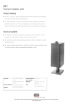
NautilusTMSCM1
Owner’s Manual
and Warranty
Figure 1
Figure 3a
Figure 2
Figure 4b
Figure 4a
0.5m –1m
110° –130°
Figure 5a
Figure 5b
Figure 3b
Figure 6
Figure 7
~
~
>1.5m
~
~
>0.5m
~
~
Figure 8a
Figure 8b
16mm
150mm
44mm
Figure 9a
Figure 9b
Contents
English
Limited Warranty...........2
Owner’s Manual............2
Dansk
Begrænset garanti ......21
Brugsanvisning ...........21
Français
Garantie limitée.............4
Manuel d’utilisation .......4
Svenska
Begränsad garanti ......23
Bruksanvisning ...........23
Deutsch
Beschränkte
Garantie .......................7
Bedienungsanleitung.....7
Ελληνικά
Περιορισµένη
εγγύηση ....................25
Οδηγίες Χρήσεως ....26
Español
Garantía limitada.........10
Manual de
instrucciones ..............10
Русский
Ограниченная
гарантия....................29
Руководство по
эксплуатации ............29
Português
Garantia limitada.........13
Manual do utilizador....13
Italiano
Garanzia limitata .........15
Manuale di istruzioni ...16
Nederlands
Beperkte garantie .......18
Handleiding ................18
.......................32
.....................32
.......................34
....................34
1
English
where the equipment can be serviced.
You can call B&W in the UK or visit our
web site to get the contact details of
your local distributor.
Limited Warranty
Dear customer,
Welcome to B&W.
This product has been designed and
manufactured to the highest quality
standards. However, if something does go
wrong with this product, B&W
Loudspeakers and its national distributors
warrant free of charge labour (exclusion
may apply) and replacement parts in any
country served by an official B&W
distributor.
This limited warranty is valid for a period of
five years from the date of purchase or two
years for electronics including amplified
loudspeakers.
Terms and Conditions
1
The warranty is limited to the repair of
the equipment. Neither transportation,
nor any other costs, nor any risk for
removal, transportation and installation
of products is covered by this warranty.
2
This warranty is only valid for the
original owner. It is not transferable.
To validate your warranty, you will need to
produce this warranty booklet completed
and stamped by your dealer on the date of
purchase. Alternatively, you will need the
original sales invoice or other proof of
ownership and date of purchase.
Owner’s manual
Introduction
Thank you for choosing B&W.
Your Nautilus™800 Series speakers are
precision transducers incorporating many
innovative techniques unique to B&W and
capable of reproducing recorded sound to
the highest standards. So that they may
perform at their best, it is essential to take
time and care with the installation process.
In particular, you must regard the listening
room as an extension of the speaker. The
acoustic character of the room can have a
profound effect on the final sound quality.
The Nautilus™SCM1 is a shallow speaker
designed for on-wall mounting, primarily for
surround channel use in conjunction with
other Nautilus™800 Series speakers.
However, it may be used wherever a
shallow speaker is required, but bearing in
mind the comments below on magnetic
shielding.
3
This warranty will not be applicable in
cases other than defects in materials
and/or workmanship at the time of
purchase and will not be applicable:
a
for damages caused by incorrect
installation, connection or packing,
b
for damages caused by any use other
than correct use described in the user
manual, negligence, modifications, or
use of parts that are not made or
authorised by B&W,
B&W maintains a network of dedicated
distributors in over 60 countries who will
be able to help you should you have any
problems your dealer cannot resolve.
c
for damages caused by faulty or
unsuitable ancillary equipment,
Unpacking (figure 1)
d
for damages caused by accidents,
lightning, water, fire heat, war, public
disturbances or any other cause
beyond the reasonable control of B&W
and its appointed distributors,
When bi-wiring, do not use the linking
cables. Take extra care with the polarity of
the connections as incorrect connection
can also impair the frequency response
through the crossover and, if the links are
left in place, may cause damage to the
amplifier by shorting its output terminals.
Lift the carton clear of the contents.
Stray magnetic fields
•
Remove the inner packing from the
product.
The speaker drive units create stray
magnetic fields that extend beyond the
boundaries of the cabinet. We recommend
you keep magnetically sensitive articles
(television and computer screens, computer
discs, audio and video tapes, swipe cards
and the like) at least 0.5m from the
speaker.
if repairs or modifications have been
executed by an unauthorised person.
4
This guarantee complements any
national/regional law obligations of
dealers or national distributors and
does not affect your statutory rights as
a customer.
4
1
2
2
8
Check in the carton for:
terminal link cables
cleaning cloth
aluminium wall plates
aluminium support plates
self adhesive rubber pads
Polythene bag containing:
Should service be required, please follow
the following procedure:
8 M5 socket screws
2 M8 socket screws
3mm Allen key
6mm Allen key
Warranty booklet
1
Connections
2
Ensure each positive terminal on the
speaker (coloured red) is connected to the
positive output terminal of the amplifier and
negative (coloured black) to negative.
Incorrect connection can result in poor
imaging and loss of bass.
•
f
If the equipment is being used outside
the country of purchase, you should
contact B&W national distributor in the
country of residence who will advise
When using the links, insert the spade into
the slot in the side of one terminal and the
crimped pin into the round side hole in the
other. There is enough clearance to insert a
spade connector from the amplifier into the
same terminal as the crimped pin.
Ascertain the optimum position for the
speaker before fixing the mounting bracket
to the wall.
We suggest you retain the packing for
future use.
2
Should you not want to bi-wire, perhaps
during the initial set-up procedure or
because you do not want to see a
multitude of cables in the room, short
cables are provided to link both positive
and both negative speaker terminals
together. (figure 3)
Fold the carton flaps right back and
invert the carton and contents.
•
for products whose serial number has
been altered, deleted, removed or
made illegible,
If the equipment is being used in the
country of purchase, you should
contact the B&W authorised dealer
from whom the equipment was
purchased.
Bi-wiring is the preferred method of
connection and involves the use of
separate cables from the amplifier to each
pair of terminals. The separation of the
signal paths improves the resolution of lowlevel detail and allows the user to optimise
the type of cable to the frequency range of
use. (figure 2)
Positioning
e
How to claim repairs under
warranty
The terminals are insulated to prevent any
likelihood of electrical shock, even when
the speakers are used with the highest
powered amplifiers, and accept a variety of
cable terminations to suit most
applications.
All connections should be made with the
equipment switched off.
There are 2 pairs of terminals at the back of
the speaker to permit bi-wiring. The lower
pair feed the bass/midrange drive unit and
the upper pair feed the tweeter.
For this reason, the Nautilus™SCM1 is only
suitable for use as a centre speaker when
using either projection, plasma or LCD
screens which are not affected by stray
magnetic fields.
Home Theatre
As a surround speaker:
There are two main ways of presenting
surround information. Older movie
soundtracks, where the surround
information was recorded on only one
channel, benefited from a very ambient,
all-enveloping presentation from the
surround speakers, with little attempt to
portray precise imaging to the sides and
rear. More modern 5.1 channel recordings
of both movies and audio have discrete left
and right surround channels, which can
convey more precise imaging. However,
images to the sides and rear are not
generally as precise as can be obtained at
the front. Sustained tones can be more
readily positioned between the speakers
than percussive sounds, which have a
tendency to collapse towards the speakers.
It is also difficult to maintain image position
for all listeners if the listening area is a
significant proportion of the area between
the five speakers. Image stability depends
on getting the right balance between all five
speakers and the ‘hot spot’ effect is even
more marked than for 2-channel audio.
With this in mind, your success in
recreating the producer’s intentions for the
surround field will depend to a great extent
on domestic constraints – how free you are
to position the speakers in an ideal position
and how large an audience you want to
cater for, relative to the size of the room.
There is no industry standard for the angle
subtended by the surround speakers at the
listening position, but most recordings are
made with the surround speakers
positioned between 110° and 130° from
front centre. Place the speakers against the
wall within this range of angles, initially on a
temporary support that raises the tweeters
approximately to ear height. This will define
whether you position the speakers on the
side or rear wall. Point the speakers
towards the centre of the listening area.
(figure 4) The wall bracket will allow the
speaker to be rotated horizontally up to
45°. If you listen in high-backed chairs, or if
the speakers are otherwise obscured, it
may be advantageous to raise them higher.
Satisfactory results can be obtained with
them up to approximately 60cm (2 feet)
above ear height.
With all speakers positioned for initial
listening tests, listen to a wide variety of
programme material – 5.1 channel audio,
action and small scale movies – and sit in
all likely listening positions. Pay particular
attention to the surround information and
the stability of the images.
If the imaging is unsatisfactory, for example
if it becomes too one sided at the extremes
of the listening area, or if you cannot place
the speakers within the preferred range,
you may be better off aiming for a more
diffuse sound field. This can give more
acceptable results in difficult situations. Try
changing the angle of the speakers so they
point away from the listening area. It may
also be advantageous to raise the speakers
well above ear height. (figure 5)
Once you have found the optimum position,
fix the speaker permanently in position (see
below).
As a front centre speaker:
If using a projection television with an
acoustically transparent screen, place the
speaker behind the centre of the screen.
Otherwise position it directly above or
below the screen, whichever is closest to
ear level.
As a front left and right speaker:
Space the speaker between 0.5m (20 in)
and 1m (40 in) from the side of the screen.
If the centre speaker is behind an
acoustically transparent screen, position
the left and right front speaker as nearly as
possible at the same height. If the centre
speaker is above or below the screen, the
height of the left and right speaker should
be between the height of the centre
speaker and the centre of the screen.
Adjust the angle of the speakers to achieve
the most realistic and stable image.
For greatest realism in home theatre
installations it is important to balance the
speakers and adjust the acoustic image to
match the size of the screen. With smaller
screens it may be more realistic to have the
left and right speakers closer together than
you might for audio alone.
Adjust the levels of the three front speakers
to get a smooth transition of sounds as
they pan across the screen. Adjust the level
of the surround speakers so that, except
for special effects, your attention is not
unduly attracted to them.
Sit in all likely listening positions when
deciding on the optimum levels.
Consult your decoder manual for further
information on how to set the levels.
2-Channel Audio
Mount the speakers so that the tweeters
are approximately at ear level.
As an initial guide: (figure 6)
Position the speakers and the centre of the
listening area approximately at the corners
of an equilateral triangle.
Keep the speakers at least 1.5m apart to
maintain left-right separation.
mechanical properties. The drive unit
suspensions will also loosen up during the
first hours of use. The time taken for the
speaker to achieve its intended
performance will vary depending on
previous storage conditions and how it is
used. As a guide, allow up to a week for
the temperature effects to stabilise and
15 hours of average use for the mechanical
parts to attain their intended design
characteristics.
Assembling and fixing the
bracket
Screws and plugs for fitting to the wall are
not supplied. Use round head screws with
a maximum body diameter of 5.0mm
(0.20 in) and a maximum head diameter of
11mm (0.4 in).
Drill and plug two holes in the wall, 150mm
(5.9 in) above where the bottom of the
speaker cabinet will be and horizontally
spaced by 44mm (1.73 in). (figure 8a) Take
special care, especially if fitting into drywall
panels, that the screws and plugs can
support the combined weight of the
speaker and bracket. Insert the screws into
the wall leaving the head 16mm (0.6 in)
clear of the surface. (figure 8b)
Assemble the support plate to the wall
plate using the four M5 screws and the
4mm Allen key. (figure 9a)
Feed the M8 screw through the slot in the
support plate into the threaded insert in the
bottom panel of the enclosure, using the
6mm Allen key. (figure 9b) Initially, position
the screw at the end of the slot furthest
from the wall plate so that the keyhole slots
are clearly visible.
If the central image is poor, try moving the
speakers closer together or toeing them in
so they point at or just in front of the
listeners. (figure 7)
Connect the cables to the speaker and
hook the wall plate over the screws in the
wall.
Fine Tuning
Adjust the speaker to be as close to the
wall as possible, commensurate with the
angle of rotation.
Before fine tuning, double check that all the
connections in the installation are correct
and secure.
If the sound is too harsh, increase the
amount of soft furnishing in the room (for
example use heavier curtains), or reduce it
if the sound is dull and lifeless.
Test for flutter echoes by clapping your
hands and listening for rapid repetitions.
Reduce them by the use of irregular
shaped surfaces such as bookshelves and
large pieces of furniture.
For the most discerning listening, remove
the cloth covered grille as described below
in the section ‘Aftercare’. The tweeter is
very delicate and its grille should be left in
position for protection. For this reason the
grille retaining ring is designed to provide
the optimum acoustic environment for the
unit and the response is less smooth with
the grille removed.
Running-in period
The performance of the speaker will change
subtly during the initial listening period. If
the speaker has been stored in a cold
environment, the damping compounds and
suspension materials of the drive units will
take some time to recover their correct
Should you need to adjust the vertical
angle of the speaker, we recommend you
use an Omnimount 30.0 WB Series wall
bracket in place of the one supplied. It may
be fitted to the additional 4 threaded inserts
in the base of the speaker.
Ancillary equipment
Speakers of this ability deserve signals of
the highest quality. Choose your electronic
equipment and interconnecting cables with
care. We can give guidance on what to
look for when choosing ancillary
equipment, but cannot recommend specific
items. The standards of such products are
improving all the time and your dealer will
be able to demonstrate a variety of suitable
up-to-date products.
In the specification we recommend a range
of amplifier powers. The higher figure is
defined by the power handling capability of
the speaker. When calculating the power
handling, it is assumed that the amplifier is
not run into clipping, which distorts the
frequency power spectrum of the signal,
and that the signal is normal programme
material. Test tones from oscillators and the
like are not applicable. The lower figure is
the minimum we consider necessary to
3
achieve reasonable listening levels without
audible distortion in the smaller room (less
than 50 m3 or 1800 cu ft). The higher the
power you use, the less likely you are to
experience amplifier clipping. You can often
tell how good an amplifier is at driving
complex speaker loads by looking at its
power rating into both 4Ω and 8Ω loads.
The nearer the ratio is to 2:1 the better, as
it indicates a good current capability.
In order to reduce the effect the cable has
on the frequency response of the speaker
to inaudible levels, the impedance of the
cable at all frequencies (measuring both
positive and negative conductors in series)
should be kept as low as possible and
certainly below 0.1Ω. At low frequencies,
the DC resistance of the cable is the
dominant factor and you should choose a
gauge of wire sufficient to achieve the
impedance requirements over the length of
cable you need to use. At mid and high
frequencies the inductive component of the
impedance can dominate the DC
resistance. This and other properties
influenced by the detailed construction of
the cable become important. Ask your
dealer for advice on the best cable for your
needs.
Aftercare
The cabinet surface usually only requires
dusting. If you wish to use an aerosol
cleaner, remove the grille first by gently
pulling it away from the cabinet. Spray onto
the cleaning cloth, not directly onto the
cabinet. The grille fabric may be cleaned
with a normal clothes brush whilst the grille
is detached from the cabinet.
Avoid touching the drive unit diaphragms,
especially the tweeter, as damage may
result.
Français
Si l’équipement est utilisé dans le pays
d’achat, veuillez contacter le
distributeur agréé de B&W qui a vendu
l’équipement.
2
Si l’équipement est utilisé dans un
pays autre que le pays d’achat, veuillez
contacter le distributeur national B&W
du pays de résidence, qui vous
indiquera où vous pouvez faire réparer
l’équipement. Vous pouvez appeler
B&W au Royaume-Uni ou consulter
notre site Web pour obtenir les
coordonnées de votre distributeur
local.
Garantie limitée
Cher Client,
Bienvenue à B&W.
Ce produit a été conçu et fabriqué en vertu
des normes de qualité les plus rigoureuses.
Toutefois, en cas de problème, B&W
Loudspeakers et ses distributeurs
nationaux garantissent une main d’œuvre
(exclusions possibles) et des pièces de
rechange gratuites dans tout pays desservi
par un distributeur agréé de B&W.
Cette garantie limitée est valide pour une
période de cinq ans à compter de la date
d’achat ou une période de deux ans pour
les composants électroniques, y compris
les haut-parleurs amplifiés.
Afin de valider votre garantie, vous devrez
présenter ce livret de garantie qui aura été
rempli et tamponné par votre revendeur le
jour de l’achat. En l’absence de ce livret,
vous devrez présenter l’original de la
facture commerciale ou une autre preuve
d’achat et de la date d’achat.
Conditions
1
La garantie est limitée à la réparation
de l’équipement. Les frais de transport
ou autres, les risques associés à
l’enlèvement, au transport et à
l’installation des produits ne sont pas
couverts par cette garantie.
2
La garantie est exclusivement réservée
au propriétaire d’origine et ne peut pas
être transférée.
3
Cette garantie ne s’applique qu’aux
produits faisant l’objet de vices de
matériaux et/ou de construction au
moment de l’achat et ne sera pas
applicable dans les cas suivants :
a
détériorations entraînées par une
installation, connexion ou un emballage
incorrect,
b
détériorations entraînées par un usage
autre que l’usage correct décrit dans le
manuel de l’utilisateur, la négligence,
des modifications ou l’usage de pièces
qui ne sont pas fabriquées ou agréées
par B&W,
c
détériorations entraînées par un
équipement auxiliaire défectueux ou
qui ne convient pas,
d
détériorations résultant de : accidents,
foudre, eau, chaleur, guerre, troubles
de l’ordre public ou autre cause ne
relevant pas du contrôle raisonnable de
B&W ou de ses distributeurs agréés,
e
les produits dont le numéro de série a
été modifié, effacé, éliminé ou rendu
illisible,
f
les produits qui ont été réparés ou
modifiés par une personne non
autorisée.
4
cette garantie vient en complément à
toute obligation juridique nationale /
régionale des revendeurs ou
distributeurs nationaux et n’affecte pas
vos droits statutaires en tant que
client.
Comment faire une réclamation
en vertu de la garantie
Veuillez respecter la procédure ci-dessous,
si vous souhaitez faire une réclamation
sous garantie :
4
1
Manuel d’utilisation
Introduction
Nous vous remercions d’avoir choisi B&W.
Vos enceintes acoustiques de la série
Nautilus™800 sont des transducteurs de
précision, comprenant de nombreuses
techniques innovantes, uniques à B&W.
Elles sont capables de reproduire vos
enregistrements au niveau de qualité le plus
élevé. Pour obtenir les meilleures
performances, il est essentiel de consacrer
le temps et l’attention nécessaires à leur
installation. En premier lieu, vous ne devez
jamais oublier que la salle d’écoute est une
extension acoustique des enceintes. Le
tempérament acoustique de la salle peut
donc avoir une influence profonde sur la
qualité sonore finale.
La Nautilus™SCM1 est une enceinte peu
profonde, conçue pour être posée contre
un mur. Elle est destinée, à l’origine, à la
reproduction des informations d’ambiances
d’une installation “Surround” équipée
d’autres enceintes de la série
“Nautilus™800”. Elle peut être utilisée,
toutefois, en tant qu’enceinte principale
lorsque la profondeur disponible n’est pas
très importante. Dans ce cas, il suffira de
garder à l’esprit les conseils que nous
formulons plus loin quant à l’émission de
champs magnétiques parasites.
B&W a constitué un réseau de distributeurs
dans plus de 60 pays. Ils sont en mesure
de vous assister au cas où votre revendeur
ne pourrait vous aider.
Deballage (figure 1)
•
Repliez complètement les abattants
puis retournez le carton avec son
contenu.
•
Soulevez le carton seul.
•
Retirez l’emballage intérieur.
Nous vous suggérons de conserver cet
emballage pour une prochaine utilisation.
NautilusTMSCM1
36
Technical Features
Nautilus™ tweeter
Kevlar® brand fibre cone bass/midrange
Matrix cabinet
Flowport
Bracket for on-wall mounting included
Description
2-way vented-box system
Drive units
1x ø25mm (1in) alloy dome high-frequency
1x ø165mm (6.5in) woven Kevlar® bass/midrange
Frequency range
-6dB at 50Hz and 30kHz
-3dB at 70Hz and 22kHz
Frequency response
80Hz – 20kHz ±2dB on reference axis
Dispersion
Within 2dB of response on reference axis
Horizontal: over 40° arc
Vertical:
over 10° arc
Sensitivity
89dB spl (2.83V, 1m)
Harmonic distortion
2nd & 3rd harmonics (90dB spl, 1m)
<1.0% 100Hz – 20kHz
<0.5% 200Hz – 18kHz
Nominal impedance
8Ω (minimum 4.7Ω)
Crossover frequencies
4kHz
Power handling
50W –120W into 8Ω on unclipped material
Max. recommended cable impedance
0.1Ω
Dimensions
Height:
Width:
Depth:
Net Weight
8.0kg (17.6 lb)
437mm (17.2 in)
372mm (14.7 in)
167mm (6.6 in) not including wall bracket
II09318 Issue 1
B&W Loudspeakers Ltd
Dale Road
Worthing West Sussex
BN11 2BH England
T +44 (0) 1903 221800
F +44 (0) 1903 221801
[email protected]
www.bwspeakers.com
UK Sales Enquiries and Service
T +44 1903 221 500
E [email protected]
B&W Loudspeakers of America
T +1 978 664 2870
E [email protected]
B&W Loudspeakers (Asia) Ltd
T +852 2 790 8903
E [email protected]
Kevlar is a registered trademark of DuPont.
Nautilus is a trademark of B&W Loudspeakers Ltd.
Copyright © B&W Loudspeakers Ltd. E & OE
Design by Thomas Manss & Company.
Printed in Spain.