1
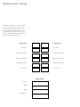
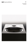
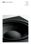
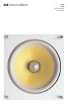
B&W Group Ltd
Dale Road
Worthing West Sussex
BN11 2BH England
T +44 (0) 1903 221800
F +44 (0) 1903 221801
[email protected]
www.bwspeakers.com
B&W Group (UK Sales)
T +44 (0) 1903 221 500
E [email protected]
B&W Group North America
T +1 978 664 2870
E [email protected]
Kevlar is a registered trademark of DuPont. Nautilus and
Matrix are registered trademarks of B&W Group Ltd.
Cobex is a registered trademark of Wardle Storeys Ltd.
Design Thomas Manss & Company. Printed in the UK.
B&W Group Ltd reserves the right to amend details of the
specification without notice in line with technical developments.
Copyright © B&W Group Ltd. E&OE
B&W Group Asia
T +852 2 790 8903
E [email protected]
Nautilus owner's manual
The Nautilus loudspeakers you have invested
in are an exact match to the first production
loudspeakers. Hand-built and tested, serial
marked and packaged individually, the refusal
to compromise at any stage from concept to
reality is a hallmark quality of Nautilus and your
guarantee of absolute satisfaction.
Loudspeaker A
Loudspeaker B
Bass driver
Bass driver
Lower midrange driver
Lower midrange driver
Upper midrange driver
Upper midrange driver
High frequency driver
High frequency driver
Crossover A
Crossover B
Quality Control
Line Insp.
Tester
Packer
Random Insp.
Contents
Introduction 5
Enclosure 6
Drive units 7
Crossover 7
Unpacking 8
Positioning 10
Installation 10
Cable connection 11
Fine tuning 12
Aftercare 12
Specification 13
Safety instructions 14
Introduction
B&W monitors are widely considered to be
the benchmark in music reproduction by
professional musicians and audiophiles alike.
The Matrix #801 has become the industry
standard monitor in recording studios around
the world, and it would be easy to rest on our
development laurels.
However, the team of audio scientists at
B&W’s Research Laboratories at Steyning
are perfectionists. For them, there are
always areas which could be improved
upon or refined.
Company founder, John Bowers, was
an exemplar of the type. For him, the most
glaring compromise in loudspeaker design
lay in the cabinet. The standard rectangular
enclosure only partially achieves its goal
of absorbing the rear radiation from the
drive unit.
Worse, it contributes resonances and
reflections from the inside, and diffraction
and reflection from the outside.
The B&W breakthrough of Matrix cabinet
construction offered a significant improvement
to the panel stiffness of the rectangular box,
but ultimately, the solution, John felt, was to
remove the cabinet completely and create
a dipole source. Sadly, time and ill-health
intervened to prevent John Bowers from
exploring this avenue of research further.
Custody of this work was passed to Matrix
inventor and top acoustic designer, Laurence
Dickie, with an enviable record of transducer
and cabinet problem solving. Laurence had
been experimenting with drivers mounted
in the curved surface of a cylinder and
encountered results not dissimilar to those
of the dipole.
Namely, that external cabinet effects could
be virtually eliminated and the intrinsic sound
of the unit heard.
He used a ring magnet outside the coil with
a thin-walled cylindrical pole piece to allow
a smooth transition from dome to enclosure.
Only one type of enclosure will provide
absolute freedom from aberration – the infinite
pipe or waveguide.
Excitingly, it became possible to imagine
that an entirely waveguide-based system
could actually work. Research showed
that the exponentially tapered pipe was an
even better absorber than the cylinder. So
complete was its absorbing action that the
pipe could be left open or closed.
This was the breakthrough. Thereafter, the
usual disciplines of the acoustic engineer’s art
came into play. Juggling the variables of driver
diameter, dispersion, break-up, excursion,
practicality, and of course, economics.
It was decided that the system should
be four-way with 300mm (12in), 100mm
(4in), 50mm (2in) and 25mm (1in) units – all
mounted in tapered lines within a diffraction
limiting enclosure.
The enclosure evolved from the original
cylinder into the sleek rolling vent design
you have purchased. The massive rolling
vent disposes of rear bass driver radiation,
whilst the exponential transmission pipes
loading the other drive units effectively deal
with internal reflection and external diffraction
at mid and high frequencies.
The drive for sonic purity is reinforced by
using an active crossover design allowing
separate amplification of each drive unit,
cutting out component crosstalk and driver
inter-reaction. Overall, the elimination
of straight lines defeats diffraction and
helps achieve virtually transparent music
reproduction.
What results is arguably the most musical
loudspeaker ever made.
Enclosure
Exponential line loading is used for all four
drive units, primarily to achieve freedom from
resonance and reflection, but also for the
damping effect on the fundamental resonance
in the low frequencies.
The two dome units are tightly coupled to
their respective wave guides via a hollow pole
magnet which causes minimal discontinuity to
the advancing wave front.
A hollow pole magnet is also to be found
behind the lower mid diaphragm supported by a
chassis which itself forms the first 50mm of the
wave guide. The tube to which this is attached is
shaped to smooth the transition from the chassis.
The distinctive natural appearance of Nautilus
is derived from the best compromise of folding
a tapered tube to save space whilst maintaining
the highest curvature-to-width ratio. Traditionally,
folded pipes have involved many 180° bends
which have serious frequency dependent
transmission properties.
10mm thick Glass Reinforced Plastic (GRP) has
been used for the exterior surface which, when
coupled with the doubly curved shape, results
in an extremely stiff enclosure. The inner turns
of the spiral are bounded by a foam filled GRP
which braces the opposite faces of the snail in
a manner similar to the Matrix type enclosure
perfected by B&W.
The external form of the Nautilus has been
achieved using a blend of hand-built forming
and advanced CAD technology borrowed from
the automotive industry. This enables B&W to
maintain mathematical accuracy of the wave
guide and to produce the final mould tool to
submillimetric accuracy.
The high gloss surface finish is the result
of using a two-part acrylic paint with a deep
lacquer coat for lustre and durability. A 50kg
block of polished terrazzo type material supports
the complete mollusc.
Drive units
Crossover
Each drive unit has been developed to
operate as a piston within its intended
frequency band, with two octaves between
the upper roll-off and the first sign of breakup modes. Extensive use of aluminium in
the diaphragms makes this possible. All
voice coils are wound on polyimide formers
to eliminate eddy-current losses, which are
particularly serious at high frequencies.
A 9.5kg (21lbs) magnet with a 100mm
(4in) voice coil acts as the massive motor of
the 300mm (12in) bass unit. This, when used
in the exponential line enclosure, results in
a high-pass behaviour so over-damped that
the traditional second-order characteristic
is replaced by two distinct first-order slopes
and no stored energy.
A 250 micron one-piece aluminium cone/
centre dome ensures coherent motion to
beyond 1.5kHz. From 220Hz to 880Hz,
a 100mm flat-fronted unit is employed to
prevent the gentle cavity resonance found
in conventional cone units at around 2kHz
interfering with the output from the upper
midrange unit. A rare earth magnet assembly
with hollow pole is used to minimise the
obstruction to the rear radiation from
the diaphragm.
Two domed units of anodised aluminium
of similar construction, 50mm and 25mm
in diameter, handle the 880Hz-3.5kHz and
3.5kHz-25kHz ranges respectively. All drive
units are completely mounted on silicone
rubber O-rings to decouple them from
the cabinet.
The division of the signal into the four required
bandwidths is accomplished in the Nautilus
Active Crossover via totally nonresonant
circuitry. Both inputs and outputs offer
single and balanced operation, the latter
being particularly useful in noisy electrical
environments, although a slight subjective
improvement has been observed when
using balanced signal interconnections at
every stage.
With suitable pre- and power amplifiers,
one unit is required for each loudspeaker
and should be sited close to the power
amplifiers. A power supply connection for
each crossover is required.
Important: your dealer must
check that the serial number
located at the rear of each
crossover unit matches that
of the loudspeaker – and that
the stated voltage is correct
for your mains supply.
Unpacking
These notes will explain in depth how to
unpack the plinth and speakers. Inside this
crate is a copy of the Nautilus user manual
that will show how to connect the Nautilus
loudspeaker system.
Attention: Please carefully read through
these instructions in full before starting
to unpack the product. Unpacking should
be carried out by two people due to the
weight of the product and awkwardness
of the shape.
Note: Remove all watches, rings, bracelets,
belts, and any other item of clothing that
might scratch the product’s surface.
A pair of Nautilus is supplied in three crates.
The two larger crates each contain one Nautilus
loudspeaker and one active crossover. One of
the large crates contains the accessory pack
and is marked as such. The small crate contains
two stone plinths.
Lay each crate flat on the ground. Open
the lids using a number 2 pozidrive screwdriver.
Unscrew all screws before lifting the lid off of
the crates.
Begin with the small crate, which holds the plinth
to support the product. Remove the lid and
card separator and set aside. The plinth weights
approximately 50kg, so it requires two people
to lift. One person should place a hand into the
slot in the plinth and raise one end. The second
person should place one hand on either side of
the plinth at the opposite end from the slot. Lift
the plinth from the crate and gently place it as
close as possible to its final installation position.
(Please note: the cable cut-out end belongs at
the back of the speaker) Repeat these steps for
the second plinth.
Place each large crate alongside the plinth or as
close as possible to the plinth. Unscrew all the
screws holding the lid on the crate. Remove the
lid and set aside. Remove the strap, length of
wadding and protective cover and place nearby.
Remove the two pieces of internal packaging
using the handholds provided. Remove the layer
of fibre wadding to reveal the speaker, active
crossover and accessory pack. Place the active
crossover and accessory pack aside.
Depending on the proximity of the plinth
to the large crate, it may be possible to feed
the wires through the slot in the plinth before
removing the product from the crate. Feed the
amplifier end of the cable through the slot in
the top of the plinth and guide it into the cable
cut-out at the rear of the plinth. (Note: it
may be easier to feed the cable through by
supporting the rear end of the plinth on the
metal rod supplied in the accessory pack.
Remove the metal rod once finished.)
Warning: do not lift the speaker using any of
its straight tubes or the part of the tweeter
enclosure forward of the split line.
One person should grasp the top of the speaker
under the main body of the tweeter enclosure.
The right hand of the second person should
support the speaker on the top of the rounded
part of the base, the left hand of the second
person should support the speaker on the front
of the speaker below the bass unit.
The person supporting the tweeter should lift
the speaker tilting it into an upright position
while the second person should support the
body of the speaker. Before removing the
speaker from the crate, place the protective
cover over the front of the speaker to prevent
damage during moving. Secure the cover with
the belt provided, ensuring the length of wadding
is placed between the strap and the speaker to
protect the enclosure.
To remove the speaker from the crate, the
person supporting the speaker should grasp
the threaded spigot from which the cable
exits at the base of the speaker while the
other person supports the front and top of the
speaker. Ensure the person holding the spigot
is positioned to the rear of the speaker so that
they can use their free hand to pull the cable
through the plinth as the speakers is lowered
into position. Guide the spigot into the slot in
the plinth.
Once the speaker is in place on the plinth, feed
first a rubber washer and secondly a metal
washer and finally a securing nut from the
accessory pack over the free end of the cable
and slide them as far as possible to the
speaker end.
One person should lean the speaker/plinth
combination forward to expose the underside
of the plinth. While the first person supports
the weight of the speaker, the second person
should feed the washers over the spigot and
screw down the nut, tightening by hand only.
Carefully stand the speaker on its plinth upright
and position it as required.
The drive units are delicate and easily damaged.
Use the plastic cover to protect them, for
example, if the speaker is to remain unused for
a long period, or if there are inquisitive children
about. Always secure the cover with the strap
and length of wadding provided. We suggest you
retain the packaging for future use.
Warning: The speaker drive units create
stray magnetic fields that extend beyond
the boundaries of the enclosure.
We recommend you keep magnetically
sensitive articles (CRT type televisions and
computer screens, computer discs, audio
and video tapes, swipe cards, etc.) at least
1m (40in) from the speaker. This does not
apply to plasma or LCD screens.
Positioning
Installation
Cable connection
Placement of any loudspeaker can significantly
influence the relative balance of sound in the
listening seat and we recommend a degree of
experimentation. In general it will be found that
Nautilus gives optimum results when “toed-in”
to a greater extent than in previous systems,
set typically at an angle of between 60° and
90°. This is due to the smooth, wide dispersion
of Nautilus which is capable of increasing the
relative significance of the side-wall reflection.
Another benefit of the dispersion characteristic
is the substantially increased listening area in
which a pleasant and realistic stereo image may
be enjoyed.
All connections should be made with the
equipment turned off. Each Nautilus comes
with its own dedicated active crossover network.
The serial number on the amplifier end of the
harness should match the serial number on
the rear of the crossover network.
The crossover can be connected to the
amplifiers with Phono leads for unbalanced
operation or XLR types for balanced operation.
Each Nautilus will require 1 separate amplifier
channel for each drive unit. The gain and phase
of each must be identical.
Each amplifier (channel) should be capable
of delivering at least 30V RMS into 6 ohms for
realistic levels of reproduction. Most amplifiers
capable of delivering 100 watts into 6 ohms
should be suitable. Connect each of the 4
crossover outputs (LF, LMF, UMF, HF) in turn
to each amplifier or amplifier channel.
The loudspeaker harness should then be
connected to the appropriate terminals on
the corresponding amplifier. The input to the
crossover should then be connected to the
output of the preamplifier. Connect the power
and turn on the crossover, followed by
the amplifiers.
High Frequency Unit
+ RED
+ ROT
+ ROUGE
– BLACK – SCHWARZ – NOIR
+ ROJO
– NEGRO
+ ROSSO
– NERO
+ MARRON
– AZUL
+ MARRONE
– AZZURRO
+ VERMELHO + ROOD
– PRETO – ZWART
Upper Mid Range Unit
+ BROWN
– BLUE
+ BRAUN + MARRON
– BLAU
– BLEU
+ CASTANHO + BRUIN
– AZUL
– BLAUW
Lower Mid Range Unit
+ YELLOW + GELB
– GREEN
– GRÜN
+ JAUNE
– VERT
+ AMARILLO + GIALLO
– VERDE
– VERDE
+ AMARELO + GEEL
– VERDE
– GROEN
60º
Connection to Nautilus is via an 8-core cable of
high purity silver on copper, terminated in bare
ends to allow the most direct connection to the
amplifier terminals.
It is generally accepted that the wires between
power amp and driver should be as short as
possible, so we do not recommend that the
captive cable be lengthened in any way.
In the majority of cases it will be most
convenient to locate the crossover units in
close proximity to the power amplifiers, with
correspondingly short line interconnects. Each
cable should be connected directly to the
respective outputs of each amplifier.
The line from pre-amplifier and crossover
is likely to be comparatively long and
should, therefore, be of high quality and low
capacitance. It is further recommended that the
balanced input of the crossover be used with
two-core screened cable – even if the pre-amp
is single ended.
In the latter case, the screen and one core
should be joined at the source end.
90º
Detail of twin cored screened lead connecting
phono to XLR plugs (pre-amp to x-over)
To Power Amp
XLR & Phono Outputs
(XLR to be used for
balanced inputs &
Phono for standard
single ended inputs)
USE ONE TYPE ONLY
FOR EACH OUTPUT
1 Meter
Listening area
Low Frequency Unit
+ ORANGE + ORANGE + ORANGE
– VIOLET
– VIOLETT – VIOLET
+ NARANJA + ARENCIO
– VIOLETA
– VIOLETTO
+ LARANJA + ORANJE
– VIOLETA – PAARS
From Pre-Amp
XLR & Phono inputs
(XLR to be used for
balanced inputs &
Phono for standard
single ended inputs)
USE ONE TYPE ONLY
10
Mains A/C in
11
Fine tuning
Before fine tuning the installation, double check
the polarity and security of the connections.
If the hand-tightened nut that holds the
Nautilus to the plinth is not done up sufficiently
tightly, it can occasionally work loose. This may
create a difficult-to-locate rattle or buzz. The
accessory pack includes a rubber washer and a
steel washer that should be employed between
the plinth and nut to eliminate this problem. The
rubber washer should rest against the plinth.
If it is not possible to position the crate near
the plinth when unpacking, the pieces of foam
covering Nautilus in the crate can be used to
support the loudspeaker close to the plinth
within reach of the loudspeaker harness.
If you need to alter the tilt of the Nautilus,
French chalk is supplied in the accessory pack
to ease movement between the speaker and
its plinth.
If the level of bass is uneven with frequency,
this is usually due to strong excitation of
resonance modes in the room. Even small
changes in the position of the speakers within
the listening room can have a profound effect
12
After care
on the perceived sound quality by altering
the excitation of these modes. Try mounting
the speakers along a different wall. Even
moving large pieces of furniture about can
have an effect.
If the general level of bass is too high, try
moving the speakers further away from the
walls. Conversely, if you need more bass, move
the speakers closer to the walls. Space behind
the speakers also improves the impression of
perspective on well recorded material.
If the sound is too harsh, increase the amount
of soft furnishing in the room. For example, use
heavier curtains. Conversely reduce the amount
of soft furnishing if the sound is dull and lifeless.
Test for flutter echoes by clapping your hands
and listening for rapid repetitions. These can
smear the sound, but may be reduced by
irregular shaped surfaces such as bookshelves
and large pieces of furniture.
As Nautilus is designed in such a way that
the units are de-coupled from the enclosure
and the base weighs a substantial 42kg.
The GRP cabinets normally only require dusting.
If you wish to use an aerosol cleaner, spray onto
the cleaning cloth, not directly onto the cabinet.
If the surface of the speaker suffers any minor
scratches, they can be polished out with fine
T-Cut or finishing compound such as “Finesse It”
by 3M.
When making or breaking connections,
ensure all power is switched off otherwise
damage may result.
Avoid touching the drive units, especially
the domes, as damage may result.
Specification
Technical features
Nautilus tube-loading
active crossover
Description
4-way tube-loaded loudspeaker system
Drive units
1x
1x
1x
1x
Frequency range
-6dB at 10Hz and 25kHz
Frequency response
25Hz - 20kHz ± 1dB on reference axis
Dispersion
Within 2dB of response on reference axis
Horizontal: over 60° arc
Vertical: over 10° arc
Crossover frequency
220Hz, 880kHz, 3.5kHz
Power amplifier
requirements
4 channels per speaker, rated 100W - 300W continuous into
8V on unclipped programme (each channel to have identical
gain and phase)
Dimensions
Height:1210mm (47.6 in)
Width:430mm (16.9 in)
Depth:1105mm (43.5 in)
Net weight
Speaker:44.5kg (98 lb)
Plinth:42kg (92 lb)
Total: 86.5kg (190lb)
Standard finishes
Midnight Blue, Black, Silver
ø300mm (12 in) aluminium cone bass
ø100mm (4 in) aluminium/polymer sandwich cone lower midrange
ø50mm (2 in) aluminium dome upper midrange
ø25mm (1 in) aluminium dome high-frequency
13
Safety instructions
1. Read these instructions.
2. Keep these instructions.
3. Heed all warnings.
4. Follow all instructions.
5. Do not use this apparatus near water.
6. Clean only with a dry cloth.
7. Do not block any ventilation holes. Install
in accordance with the manufacturer's
instructions.
8. Do not install near any heat sources such
as radiators, heat registers, stoves or other
apparatus that produces heat. If the
crossover unit is to be installed in a rack with
power amplifiers, install the crossover below
the amplifiers.
9. Do not defeat the purpose of any polarised
or grounding type plug. A polarised plug
has two blades with one wider than the
other. A grounding type plug has two blades
and a third grounding prong. The wide blade
or the grounding prong are provided for
your safety. If the provided plug does
not fit your outlet, consult an electrician for
replacement of the obsolete outlet.
10. Protect the power cord from being walked
on or pinched, particularly at plugs,
convenience receptacles and the point
where they exit from the apparatus. Take
similar precautions with the cable to the
loudspeaker.
11. Only use attachments/accessories
recommended by the manufacturer.
12. Unplug this apparatus during lightning
storms or when unused for long periods
of time. Similarly unplug all other powered
equipment in the installation.
13. Use only with the cart, stand, tripod, bracket
or table specified by the manufacturer, or
sold with the apparatus. When a cart is
used, use caution when moving the cart/
apparatus combination to avoid injury from
tip over.
CAUTION
RISK OF ELECTRIC
SHOCK DO NOT
Caution: to reduce the risk of
electric shock, do not remove the
back panel.no user-serviceable
parts inside. refer servicing to
qualified personnel.
English
Deutsch
Français
Español
Warnings
To prevent fire or shock hazard, do not expose this
equipment to rain or moisture.
Sicherheitshinweise
Zum Schutz vor Feuer oder einem elektrischen Schlag das
Gerät niemals Regen oder Feuchtigkeit aussetzen.
Avertissements importants
Pour éviter tout risque d’incendie ou d’électrisation, ne
jamais exposer ces appareils à la pluie ou l’humidité.
Observe all warnings on the equipment itself. To avoid
electrical shock, do not open the enclosure. There are no
user serviceable parts inside. Refer all service questions to
an authorised B&W dealer.
Alle Warnhinweise auf dem Gerät müssen genau beachtet
werden. Dadurch können Personen- und Sachschäden
vermieden werden. Um die Gefahr eines elektrischen
Schlags zu reduzieren, nicht das Gehäuse öffnen. Im
Innern befinden sich keine vom Bediener zu wartenden
Teile. Wenden Sie sich bei Servicefragen stets an einen
autorisierten B&W-Fachhändler.
Observez rigoureusement tous les avertissements
imprimés sur les appareils eux-mêmes. Pour éviter tout
risque d’électrisation, ne jamais ôter le capot. Il n’y a pas
de pièce modifiable par l’utilisateur à l’intérieur. En cas de
problème, adressez-vous à votre revendeur agréé B&W.
Advertencias
Pare prevenir que se produzcan incendios o descargas
eléctricas, no exponga este producto a la lluvia o la
humedad.
To prevent electric shock, do not use this (polarised) power
plug with an extension cord receptacle or other outlet
unless the blades can be fully inserted to prevent blade
exposure.
Ensure that the voltage indicated on the panel matches
that of the power supply.
Explanation of Graphical Symbols
The lightning flash within an equilateral triangle is
intended to alert you to the presence of uninsulated
“dangerous voltage” within the product’s enclosure
that may be of sufficient magnitude to constitute an
electric shock to persons. The exclamation point
within an equilateral triangle is intended to alert you
to the presence of important operating and
maintenance (servicing) instructions in the literature
accompanying the appliance.
Replace mains fuse only with the same type and rating as
shown on the voltage label placed near the mains input
socket.
Switch off the power and remove the mains cable from the
case before changing the fuse.
the equipment must be earthed (grounded).
To ensure adequate cooling do not obstruct
the ventilation holes.
Do not insert objects through the amplifier
ventilation holes.
Important for uk only:
The wires in this mains lead are coloured in
accordance with the following code:
green-and-yellow: earth
blue: neutral
brown: live
As the colours of the wires in the mains lead of this apparatus
may not correspond with the coloured markings identifying the
terminals in your plug, proceed as follows: the wire which is
coloured green and yellow must be connected to the terminal in
the plug which is marked with the letter E, or by the earth symbol
or coloured green or green and yellow. The wire which is
coloured blue must be connected to the terminal which is
marked with the letter N or coloured black. The wire which is
coloured brown must be connected to the terminal which is
marked with the letter L or coloured red.
Italiano
14. Refer all servicing to qualified personnel.
Servicing is required when the apparatus
has been damaged in any way, such as
power-supply cord or plug is damaged,
liquid has been spilled or objects have fallen
into the apparatus, the apparatus has been
exposed to rain or moisture, does not
operate normally or has been dropped.
15. To reduce the risk of fire or electric shock,
do not expose this apparatus to rain or
moisture.
16. The apparatus has Class 1 construction and
must be connected to a mains socket outlet
with a protective earthing (grounding)
connection.
17. The apparatus may be isolated from the
mains power supply, either by using the
power switch located over the power inlet
socket at the rear of the apparatus, or by
removing the plug from the wall socket
outlet. Ensure that one or both are readily
accessible.
Avvertenze
Per prevenire incendi o folgorazioni non esporre
l’apparecchiatura a pioggia o umidità.
Rispettare tutte le avvertenze indicate sulle apparecchiature
stesse. Per evitare scosse non aprire il cabinet. Non
contiene parti riparabili dall’utente. Per qualsiasi problema
rivolgersi ai Rivenditori Autorizzati B&W.
Per evitare folgorazioni, non utilizzare questa spina di
alimentazione (polarizzata) con una prolunga o altro se le
lamelle non si inseriscono completamente nella presa per
evitare l’esposizione della lamella stessa.
Controllare che il voltaggio indicato sull’apparecchio
corrisponda a quello della rete elettrica.
Sostituire il fusibile di rete solo con uno dello stesso tipo e
dello stesso valore come indicato sull’etichetta che riporta
il voltaggio dell’apparecchio posta vicino all’ingresso del
cavo di alimentazione.
Spegnere l’apparecchio e togliere il cavo di alimentazione
dalla presa elettrica prima di cambiare il fusibile.
Verwenden Sie kein Verlängerungskabel. Eine
hochbelastbare Mehrfachsteckdose kann eingesetzt
werden, wenn sie (und die Wandsteckdose) ausreichende
Strommengen für alle an sie angeschlossenen
Komponenten liefern können.
Bevor Sie das Gerät in Betrieb nehmen, prüfen Sie, ob die
Betriebsspannung mit der örtlichen Netzspannung
übereinstimmt. Die Betriebsspannung ist am Gerät
angegeben.
Pour éviter tout risque d’électrisation, ne pas utiliser la
prise d’alimentation secteur fournie (polarisée) avec un
cordon-rallonge, ou dans une prise murale qui ne permette
pas d’utiliser correctement toutes les broches de la prise
d’origine.
Vérifiez bien avant branchement que la tension
d’alimentation indiquée sur le panneau arrière de l’appareil
est conforme à celle de votre installation électrique.
Setzen Sie niemals Sicherungen ein, deren Wert bzw. Typ
vom angegebenen abweicht.
Ne remplacez le fusible de protection d’alimentation
qu’avec un modèle rigoureusement de même type et de
même valeur, comme indiqué près de la prise
d’alimentation secteur, sur l’étiquette d’indication de la
tension d’alimentation de votre installation.
Schalten Sie den Strom ab und entfernen Sie das
Éteignez l’appareil ET débranchez sa prise d’alimentation
Netzkabel, bevor Sie die Sicherung wechseln.
secteur avant de changer le fusible.
Das Gerät muss geerdet werden.
Cet appareil doit être mis à la terre.
Verdecken Sie die Ventilationsöffnungen nicht, damit eine
ausreichende Luftzirkulation gewährleistet ist.
Pour garantir une ventilation correcte, ne pas obstruer les
ouïes pratiquées dans le coffret.
Stecken Sie keine Gegenstände in die
Ventilationsöffnungen.
Ne jamais tenter d’insérer des objets dans les orifices de
ventilation de l’amplificateur.
Português
Nederlands
Avisos
Para evitar o risco de fogo ou choque eléctrico, não
exponha este produto à chuva ou humidade.
Waarschuwingen
Om brand of schokken te voorkomen het product nooit
blootstellen aan regen en vocht.
Observe todos os avisos no equipamento propriamente
dito. De forma a evitar choque eléctrico, não abra a tampa.
Não existem partes reparáveis pelo utilizador no interior.
Coloque todas as questões de assistência a um agente
autorizado B&W.
Let vooral ook op waarschuwingen die op het product zelf
staan aangegeven. Om elektrische schokken te voorkomen
het product nooit openen. Er bevinden zich in het product
geen door de gebruiker zelf te repareren onderdelen. Laat
alle service aan een geautoriseerde B&W dealer over.
Para prevenir choque eléctrico, não utilize esta ficha de
alimentação (polarizada) com uma extensão ou outra
tomada a menos que os pernes sejam inseridos
completamente evitando assim a sua exposição.
Om schokken te voorkomen met deze gepolariseerde
netstekker geen verlengsnoer of andere combinatie
gebruiken tenzij de pennen geheel kunnen worden
ingestoken om te voorkomen dat spanningvoerende delen
kunnen worden aangeraakt.
Assegure-se que a voltagem indicada no painel coincide
com a corrente de sector de alimentação.
Substitua o fusível de corrente apenas por outro do
mesmo tipo e especificação, como mostra a etiqueta de
voltagem colocada perto da tomada de entrada de
corrente.
Observe todas las advertencias que figuran en el producto
propiamente dicho. Para evitar que se produzcan
descargas eléctricas, no acceda al interior de los filtros
activos. Consulte cualquier cuestión relacionada con el
mantenimiento del producto a un distribuidor autorizado
de B&W.
Asegúrese de que la tensión indicada en el panel del
producto concuerde con la de la fuente de alimentación.
Sustituya el fusible de protección principal única y
exclusivamente por uno del mismo tipo y valor que el
indicado en la etiqueta situada cerca de la toma de
alimentación.
Antes de cambiar el fusible, desconecte el aparato y retire
el cable de alimentación.
Este producto debe ser conectado a tierra (masa).
Para asegurar una ventilación adecuada, no obstruya los
orificios de refrigeración.
No coloque objetos en las ranuras de refrigeración de los
equipos electrónicos.
Controleer of de op het paneel aangegeven netspanning
overeenkomt met die ter plaatse.
Vervang netzekeringen uitsluitend door hetzelfde type met
dezelfde waarde, als aangegeven op de sticker nabij de
lichtnetaansluiting.
Desligue a corrente e retire o cabo de alimentação da
caixa antes de substituir o fusível.
Schakel het product uit en neem de stekker uit het
stopcontact voordat u een zekering vervangt.
O equipamento deve ser ligado à terra.
Het apparaat dient te worden geaard.
De molde a assegurar uma ventilação adequada não
obstrua os orifícios de ventilação.
Om zeker te zijn van voldoende koeling de
ventilatiesleuven niet afdekken.
Não insira objectos através dos orifícios de ventilação.
Zorg ervoor dat er geen vreemde voorwerpen via de
ventilatiesleuven kunnen binnendringen.
Questo apparecchio richiede la messa a terra.
Per garantire un raffreddamento adeguato
dell’apparecchio, non ostruite i fori di ventilazione.
Non inserire oggetti nei fori di aerazione.
14
15
16