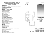
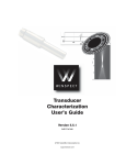
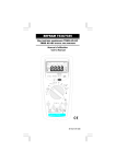
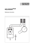
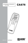
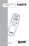
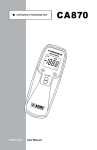
1
n
DC/AC MICROPROBE
ON
OL
!
• 1 mV/mA
• OFF
AEMC
®
INSTRUM ENTS
ENGLISH
DC/AC MicroProbe
Model K100
User Manual
K100
K110
Statement of Compliance
Chauvin Arnoux®, Inc. d.b.a. AEMC® Instruments
certifies that this instrument has been calibrated
using standards and instruments traceable to
international standards.
We guarantee that at the time of shipping your
instrument has met its published specifications.
An NIST traceable certificate may be
requested at the time of purchase, or obtained
by returning the instrument to our repair and
calibration facility, for a nominal charge.
The recommended calibration interval for this
instrument is 12 months and begins on the date of
receipt by the customer. For recalibration, please
use our calibration services. Refer to our repair
and calibration section at www.aemc.com.
Serial #: _ ________________________________
Catalog #: 1200.67 / 2111.73
Model #: K100 / K110
Please fill in the appropriate date as indicated:
Date Received: __________________________________
Date Calibration Due: ________________________
Chauvin Arnoux®, Inc.
d.b.a AEMC® Instruments
www.aemc.com
Table of Contents
1. INTRODUCTION................................................................................ 3
1.1 International Electrical Symbols.................................................3
1.2 Definition of Measurement Categories......................................4
1.3 Receiving Your Shipment...........................................................4
1.4 Ordering Information..................................................................4
2. PRODUCT FEATURES....................................................................... 5
2.1 Description.................................................................................5
2.2 Model K100 Features................................................................6
2.3 Model K110 Features.................................................................7
3. SPECIFICATIONS............................................................................. 8
3.1 Electrical Specifications.............................................................8
3.2 Environmental Specifications.....................................................9
3.3 Mechanical Specifications.........................................................9
3.4 Safety Specifications.................................................................9
3.5 Typical Frequency Response..................................................10
4. OPERATION................................................................................... 11
4.1 Making Measurements with the K100/K110............................ 11
4.2 Indicator Lights - Green and Red LEDs................................... 11
4.3 Model K100 Operation Examples............................................12
DC Current Measurement Example (K100)...............................12
DC Current Measurement Example - Current Reversed......... 12
Two-Wire Sum-of-Currents Example (K100).............................13
Two-Wire Current Differential Example (K100)..........................13
Oscilloscope Measurement Example (K100).............................14
Maximum Step Discontinuity Example (K100)...........................14
4.4 Model K110 Operation Examples............................................15
Measuring the DC Component of an (AC+DC) Waveform ..... 15
Measuring the AC Component of an (AC+DC) Waveform.......15
Oscilloscope Measurement Example (K110).............................16
4.5 Tips For Making Precise Measurements.................................16
4.6 Residual Readings Following Severe Overloads.....................19
5. MAINTENANCE.............................................................................. 20
5.1 Warning ..................................................................................20
5.2 Battery Installation...................................................................20
5.3 Cleaning...................................................................................21
Repair and Calibration............................................................................22
Technical and Sales Assistance.............................................................22
Limited Warranty....................................................................................23
Warranty Repairs....................................................................................23
CHAPTER 1
INTRODUCTION
WARNING
These safety warnings are provided to ensure the safety of personnel
and proper operation of the instrument.
• Read the instruction manual completely and follow all the safety
information before attempting to use or service this instrument.
• Use caution on any circuit: Potentially high voltages and currents may be present and may pose a shock hazard.
• Read the Safety Specifications section prior to using the Model
K100/K110. Never exceed the maximum voltage ratings given.
• Safety is the responsibility of the operator.
• NEVER open the back of the instrument while connected to any
circuit or input.
• ALWAYS connect the Model K100/K110 adapter to the display
device before clamping the probe onto the sample under test.
• ALWAYS inspect the instrument, probe, probe cable and
output terminals prior to use. Replace any defective parts
immediately.
• NEVER use the Model K100/K110 on electrical conductors
rated above 300V CAT II, EN61010-1.
1.1
International Electrical Symbols
This symbol signifies that the instrument is protected by double or
reinforced insulation. Use only specified replacement parts when
servicing the instrument.
This symbol on the instrument indicates a WARNING and that
the operator must refer to the user manual for instructions before
operating the instrument. In this manual, the symbol preceding
instructions indicates that if the instructions are not followed,
bodily injury, installation/sample and product damage may result.
Risk of electric shock. The voltage at the parts marked with this
symbol may be dangerous.
DC/AC MicroProbe Models K100 and K110
3
1.2
Definition of Measurement Categories
CAT I: For measurements on circuits not directly connected to the AC
supply wall outlet such as protected secondaries, signal level,
and limited energy circuits.
CAT II: For measurements performed on circuits directly connected to
the electrical distribution system. Examples are measurements
on household appliances or portable tools.
CAT III: For measurements performed in the building installation at
the distribution level such as on hardwired equipment in fixed
installation and circuit breakers.
CAT IV: For measurements performed at the primary electrical supply
(<1000V) such as on primary overcurrent protection devices,
ripple control units, or meters.
1.3
Receiving Your Shipment
Upon receiving your shipment, make sure that the contents are consistent
with the packing list. Notify your distributor of any missing items. If the
equipment appears to be damaged, file a claim immediately with the carrier and notify your distributor at once, giving a detailed description of any
damage.
1.4
Ordering Information
DC/AC MicroProbe Model K100........................................... Cat. #1200.67
DC/AC MicroProbe Model K110........................................... Cat. #2111.73
Both models include an electronic plug-in module with an attached current probe, 9V battery,
and user manual
Order Accessories and Replacement Parts Directly Online
Check our Storefront at www.aemc.com/store for availability
4
DC/AC MicroProbe Models K100 and K110
CHAPTER 2
PRODUCT FEATURES
2.1
Description
Model K100 and Model K110 are low current measurement instruments
that feature a compact, high sensitivity current probe. Unlike other instruments, the Model K100 exhibits a wide dynamic operating range, which
extends from below 100µA to ± 4.5A peak, from DC to 2.0kHz*, without the
need for ranging. The K110 has an operating range of 100µA to ± 450mA
Peak, from DC to 1500Hz.*
Models K100 and K110 are designed to be operated in conjunction with a
digital multimeter, oscilloscope or recording device. The MicroProbe outputs the current measured in the form of a voltage that is the image of the
current, in shape and amplitude. The Model K100 outputs 1mV per mA of
measured current. The Model K110 outputs 10mV per mA of measured
current. To take advantage of the Model K100 high sensitivity, best results
are obtained through 4-1/2 digit (or more) DMM with a relative zero function. The Model K110 was designed to provide the operator with enhanced
low current linearity and accuracy, but is limited to 450mA Peak current.
The Model K100/K110 always outputs a signal proportional to the total
current (AC+DC) in the conductor under test. This has proven to be the
most versatile signal output format, and allows the user to isolate and
measure DC and AC components of measured current separately, if so
desired. Typical applications include 4 to 20mA loop measurements, automotive current applications, benchtop electronic current consumption in
circuits, and other applications requiring very low current measurements
in crowded areas.
* See Electrical Specifications
DC/AC MicroProbe Models K100 and K110
5
2.2
Model K100 Features
1
7
2
3
4
5
8
6
Figure 1
1. Positive: Red banana plug (+)
2. Negative: Black banana plug (-)
3. Power ON indicator (green LED)
4. OVERLOAD indicator (red LED)
5. Power switch
6. Zero adjust knob (push in and turn to zero)
7. Probe window aperture
8. Probe handle
6
DC/AC MicroProbe Models K100 and K110
2.3
Model K110 Features
1
7
2
3
4
5
8
®
6
Figure 2
1. Positive: Red banana plug (+)
2. Negative: Black banana plug (-)
3. Power ON indicator (green LED)
4. OVERLOAD indicator (red LED)
5. Power switch
6. Zero adjust knob (push in and turn to zero)
7. Probe window aperture
8. Probe handle
DC/AC MicroProbe Models K100 and K110
7
CHAPTER 3
SPECIFICATIONS
3.1
Electrical Specifications
Model K100
Model K110
Current Range:
0 to ± 4.5A DC
0 to 3 Arms (sinusoidal)
Current Range:
0 to ± 450mA DC
0 to 300mA rms
Output (Vout): 1mV/mA
Output (Vout): 10 mV/mA
Resolution:
DC: 50µA typical
AC: 100µA typical
Resolution:
DC: 50µA typical,
AC: 100µA typical
Accuracy:
DC: 1% reading ± 200µA
AC: 2% reading ± 200µA
Accuracy:
DC: 0.5% reading ± 150µA
AC: 0.8% reading ± 200µA
Output Noise:
< 100µV, DC to 3kHz
Output Noise:
<100µV, DC to 3kHz
Frequency Response:
DC to 2kHz (@ -3dB sine)
Frequency Response:
DC to 1.5kHz (@ -3dB sine)
Zero Adjust:
± 25mA
Zero Adjust:
± 25mA
Rise Time: < 200µS, 10% to 90% Vout
Fall Time: < 200µS, 90% to 10% Vout
Output Impedance: 200Ω
Probe Inductance: <1µH
Influence of Adjacent Conductor: <50µA/A (K100); <100µA/A (K110)
Influence of Earth’s Field: <120µA, null to maximum
Overload LED (Red): Indicates momentary or continuous overload
Power LED (Green): Indicates power ON and good battery
LED (Green) ON between 6.5 to 10V
Power Source: 9V alkaline, NEDA 1604, 6LR61 or IEC 6LF22
Battery life 20H approx. with alkaline battery
(Reference Conditions: 23°C ± 3°, 20 to 75% RH; battery voltage 9V ± 0.1V; earth’s magnetic
field < 40 A/m; absence of AC fields; input impedance of display device ≥ 1MΩ/100 pF; DC
or sinusoidal AC current 45 to 65Hz.)
8
DC/AC MicroProbe Models K100 and K110
3.2
Environmental Specifications
Operating Temperature: -14° to 131°F (-10° to 55°C)
Storage Temperature: -40° to 176°F (-40° to 80°C)
Humidity: <95% @ ≤ 35°C, 75% @ 55°C
3.3
Mechanical Specifications
Dimensions (Probe): 4.4 x 0.6 x 1.0" (111 x 15 x 25mm)
Dimensions (Electronic Module): 4.9 x 2.5 x 1.1" (124 x 64 x 28mm)
Weight: 9 oz (250g)
Connectors: Two 4mm banana plugs; standard 3/4" (19mm) spacing
Maximum Conductor Diameter: 3/16", 0.180" (4.5mm)
Cable Length: 5 ft (1.5m)
3.4
Safety Specifications
Working Voltage:
EN61010-1, 300V CAT II
CE mark for Electromagnetic Compatibility.
Immunity (EN 50082.1), IEC 1000-4-3 aptitude criteria A:
DC: 15mV @ 0, AC (60Hz): 2dB from 10mA to 4.5A
Emmissivity (EN 50081.1): negligible
Drop Test: 1m per IEC 1010
Shocks: 100G per IEC 68-2-27
Vibrations: IEC 529
Protection Index: IP 40 per IEC 529
Electromagnetic Compatibility:
EN 50082-1 class A EN 50081-1
*All specifications are subject to change without notice.
DC/AC MicroProbe Models K100 and K110
9
3.5
Typical Frequency Response
Model K100
2200
2000
1800
1600
1400
1200
1000
800
600
400
200
50
Frequency (Hz)
0
-0.5
Decibels (dB)
-1.0
-1.5
30 mA
-2.0
3.0 A
-2.5
-3.0
-3.5
-4.0
Figure 3
Model K110
1600
1400
1200
1000
800
600
400
200
0
Frequency (Hz)
0
-0.5
Decibels (dB)
-1.0
-1.5
0 - 300 mA RMS
-2.0
-2.5
-3.0
-3.5
-4.0
Figure 4
10
DC/AC MicroProbe Models K100 and K110
CHAPTER 4
OPERATION
4.1
Making Measurements with the K100/K110
• Remove any conductor from within the probe jaws.
• Plug the electronic module into the displaying device (e.g., DMM, oscilloscope). Note the polarity of the module output banana plugs (red =
positive [+], black = negative [-]).
• Select the appropriate range on displaying device (e.g., DMM, oscilloscope). Note that the module output is 1mV/mA for Model K100 and
10mV/A for model K110.
• Turn displaying device power ON. Turn on the Model K100/K110 (the
green LED should be ON, and the red LED OFF).
• With the probe disconnected from test samples (no conductor in probe
jaw window), adjust the zero control (push in the knob and turn) to
read zero volts on the displaying device. In the unlikely event where
the zero point is unobtainable, refer to Residual Readings Following
Severe Overloads (§ 4.6) - the Model K100/K110 probe may be temporarily magnetized.
• Clamp the probe around the conductor to be tested. The displaying
device should now display the measured conductor current. In DC, a
positive reading indicates current flowing in the direction of the arrow
on the probe. A negative reading indicates current flow in the opposite
direction of the arrow.
4.2
Indicator Lights - Green and Red LEDs
• The Green LED indicates that the Model K100/K110 is ON and that the
battery is good. The Green LED will not light under low battery conditions. Replace the 9V battery if the green LED is not lit.
• The Red LED indicates a momentary or continuous overload of the
instrument. Readings taken while the Red LED is ON or FLASHING
should be considered inaccurate. Momentary or continuous currents
exceeding ± 4.7A for Model K100 and 470mA for Model K110, and
dynamic currents with large step discontinuities will cause the red LED
to turn ON.
DC/AC MicroProbe Models K100 and K110
11
4.3
Model K100 Operation Examples
DC Current Measurement Example (K100)
• Conductor carrying 20.0mADC in the direction of the arrow
• Voltmeter placed in DC Volts mode
• Voltmeter displays 20.0mV
DC
CV
V
A
20.0 mV
20 mA DC
PUSH
DC Zero
Figure 5
DC Current Measurement Example - Current Reversed (K100)
• Conductor carrying 20.0mADC in opposite direction of arrow
• Voltmeter placed in DC Volts mode
• Voltmeter displays -20.0mV
DC
CV
V
A
-20.0 mV
20 mA DC
PUSH
DC Zero
Figure 6
12
DC/AC MicroProbe Models K100 and K110
Two-Wire Sum-of-Currents Example (K100)
• Two conductors in probe aperture (note orientations)
• Voltmeter placed in DC Volts mode
• Voltmeter displays 18.0mV
DC
CV
V
A
18.0 mV
7 mA DC
11 mA DC
PUSH
DC Zero
Figure 7
Two-Wire Current Differential Example (K100)
• Two conductors in probe aperture (note orientations)
• Voltmeter placed in DC Volts mode
• Voltmeter displays -4.0mV
DC
CV
V
A
-4.0 mV
7 mA DC
11 mA DC
PUSH
DC Zero
Figure 8
DC/AC MicroProbe Models K100 and K110
13
Oscilloscope Measurement Example (K100)
• Conductor carrying a 2A peak AC waveform
• Model K100 connected to oscilloscope
To Oscilloscope
2.0 V
0
-2.0 V
Current Waveform
Oscilloscope
Output
2.0 A
0
ON
OL
• 1 mV/mA
• OFF
AEMC
®
DC/AC MicroProbe
Model K100
I N S T R U M E N TS
Figure 9
Maximum Step Discontinuity Example (K100)
• Conductor carrying non-sinusoidal AC
• Model K100 connected to oscilloscope
• Maximum allowable step-discontinuity 2A
Note: Step Discontinuities
To Oscilloscope
2.0 V
0
Current Waveform
-2.0 V
2A
Oscilloscope
Output
ON
0
-2A
OL
• 1 mV/mA
• OFF
AEMC
INSTRUMENTS
®
DC/AC MicroProbe
Model K100
Figure 10
14
DC/AC MicroProbe Models K100 and K110
4.4
Model K110 Operation Examples
Measuring the DC Component of an (AC+DC) Waveform (K110)
• Conductor carrying 20.0mADC + 15.0mAAC
• Voltmeter placed in DC Volts mode
• Voltmeter displays 200.0mV
15 mA AC
+
20 mA DC
DC
CV
V
A
200.0 mV
PUSH
DC Zero
Figure 11
Measuring the AC Component of an (AC+DC) Waveform (K110)
• Conductor carrying 20.0mADC + 15.0mAAC
• Voltmeter placed in AC Volts mode
• Voltmeter displays 150.0mV
15 mA AC
+
20 mA DC
DC
CV
V
A
150.0 mV
PUSH
DC Zero
Figure 12
DC/AC MicroProbe Models K100 and K110
15
Oscilloscope Measurement Example (K110)
• Conductor carrying a 0.2A peak AC waveform
• Model K110 connected to oscilloscope
To Oscilloscope
2.0 V
0
-2.0 V
Oscilloscope
Output
Current Waveform
0.2 A
0
ON
OL
-0.2 A
• 10 mV/mA
• OFF
AEMC
INS TRUME NTS
®
DC/AC MicroProbe
Model K110
Figure 13
4.5
Tips For Making Precise Measurements
The Model K100/K110 is capable of making measurements of DC and low
frequency currents over a wide range. Here are some key considerations
for getting the most accuracy from your displaying instrument:
• When using the Model K100/K110 with a meter, it is important to
select the range that provides the best resolution. Failure to do
this may result in measurement errors. The examples shown on
the next page use an ordinary 3-1/2 digit DMM with the Models
K100 and K110, to measure 16.7mADC.
16
DC/AC MicroProbe Models K100 and K110
Model K100
Resolution: 10mV
Display Error: 19.8%
Resolution: 1mV
Display Error: 1.8%
Resolution: 100µV
Display Error: 0%
2V
20
V
2V
20
V
0m
V
20
20
20
2V
V
0m
V
V
0m
20
.02 V
PUSH
PUSH
PUSH
DC Zero
DC Zero
DC Zero
16.7mA
Figure 14
Model K110
2V
20
V
2V
20
V
0m
V
Resolution: 100µV
Display Error: 0%
20
20
20
2V
Resolution: 1mV
Display Error: 0%
V
0m
V
V
0m
20
Resolution: 10mV
Display Error: 1.8%
PUSH
PUSH
PUSH
DC Zero
DC Zero
DC Zero
16.7mA
Figure 15
DC/AC MicroProbe Models K100 and K110
17
• Always zero the Model K100/K110 prior to making a measurement. See §4.1 for procedure.
• Make sure that probe jaw mating surfaces are free of dust and
contamination. Contaminants cause air gaps between sensor
halves, making the Model K100/K110 susceptible to external
magnetic fields which can contribute to measurement errors. See
§5.3 for cleaning procedure.
• Do not allow probe jaws to abruptly snap closed from the open
state. This can lead to residual readings. If this happens, the
Model K100/K110 will need to be rezeroed.
• Beware of short-circuit currents. Large in-rush currents (which can
occur when power is first applied in a circuit) and large high-current transients may cause varying degrees of residual readings.
If in doubt of a particular reading, remove the probe from the conductor under test and check to see that the display device returns
zero. If not, it will be necessary to rezero the Model K100/K110.
• When using the Model K100/K110 to measure AC currents, keep
in mind the maximum current ratings and the frequency response
curves shown in the electrical specifications section. Dynamic
currents that contain large step discontinuities and/or frequency
constituents near or beyond the measurement passband are
subject to measurements errors and waveform distortion (oscilloscope display). If the red LED comes on during measurement,
the MicroProbe’s output signal may be in error.
Many DVMs provide null (relative) measurement capability. A DVM placed
in the null mode displays the difference between a stored null value and
the input signal.
• You can use a DVM’s null function in place of the external DC zero
control to cancel any DC offset from the K100/K110. The DVM
null function should be enabled with the probe removed from the
conductor immediately before measurement.
• You can use a DVM’s null function to display changes in measured current from a fixed (constant) level. In this application, the
DVM null function is enabled with the probe connected to the conductor.
When making null (relative) measurements, the probe aperture current
(not displayed current) must not exceed the maximum ratings set forth in
the specifications section.
18
DC/AC MicroProbe Models K100 and K110
4.6
Residual Readings Following Severe Overloads
Large short-circuit and transient currents outside the operating range
of the Model K100/K110 may cause large residual readings. In extreme
cases, the Model K100/K110 will not zero. If this happens:
• Remove the probe from the test conductor.
• Open the probe and release, allowing the jaws to snap back.
Repeat this step several times.
• Rezero the instrument before making successive measurements.
DC/AC MicroProbe Models K100 and K110
19
CHAPTER 5
MAINTENANCE
5.1
Warning
Please make sure that you have already read and fully understand the
WARNING section on page 2.
• To avoid electrical shock, do not attempt to perform any servicing
unless you are qualified to do so.
• To avoid electrical shock and/or damage to the instrument, do not get
water or other foreign agents into the case. Turn the Model K100/K110
OFF and disconnect the unit from all circuits before opening the case.
5.2
Battery Installation
Your Model K100/K110 has been shipped with a new 9V battery installed.
To replace the battery:
• Remove probe from any conductor and place it away from any active
conductors, circuitry, etc.
• Unplug electronic module from display device
(e.g. DMM, oscilloscope).
• Remove the screws from the bottom cover of the electronic module.
• Replace battery with a new 9V alkaline type.
• Replace bottom cover and re-attach with screws.
BATTERY CLIP
REMOVE PROBE FROM TESTED CIRCUIT
BEFORE OPENING THE CASE.
AEMC INSTRUMENTS, BOSTON, MA
MADE IN USA
INPUT
! WARNING
!
CURRENT : 0-4500 mA DC / AC peak
RATING
!
300 V, IEC 1010-1, CAT. II
BATTERY: 9 V, NEDA 1604, 6LF22, 6LR61
SCREWS
Figure 16
20
DC/AC MicroProbe Models K100 and K110
5.3
Cleaning
To ensure optimum performance, it is important to keep the probe jaw
mating surfaces clean at all times. Failure to do so may result in increased
earth’s field susceptibility and overall errors in readings. The following is
the recommended procedure for cleaning the probe sensor:
(1) Apply a few drops of isopropyl alcohol to an ordinary sheet of white photocopy paper.
(2) Open probe to expose the mating surfaces of the sensor and insert the sheet of paper into the jaws. Allow the jaws to close.
(3) With the jaws closed, pull free the end of the paper through the jaws
until it releases.
(4) Repeat step (3) several times, using a new (dry) section of paper each time.
(5) Open probe and inspect mating surfaces. They should be free of dust particles or any other contamination. Otherwise, repeat the cleaning process starting again at step (1).
1
AL
CO
HO
L
2
3
4
Figure 17
DC/AC MicroProbe Models K100 and K110
21
Repair and Calibration
To ensure that your instrument meets factory specifications, we recommend
that it be scheduled back to our factory Service Center at one-year intervals
for recalibration, or as required by other standards or internal procedures.
For instrument repair and calibration:
You must contact our Service Center for a Customer Service Authorization
Number (CSA#). This will ensure that when your instrument arrives, it will be
tracked and processed promptly. Please write the CSA# on the outside of the
shipping container. If the instrument is returned for calibration, we need to
know if you want a standard calibration, or a calibration traceable to N.I.S.T.
(Includes calibration certificate plus recorded calibration data).
Ship To:
Chauvin Arnoux®, Inc. d.b.a. AEMC® Instruments
15 Faraday Drive
Dover, NH 03820 USA
Phone:(800) 945-2362 (Ext. 360)
(603) 749-6434 (Ext. 360)
Fax: (603) 742-2346 or (603) 749-6309
E-mail:[email protected]
(Or contact your authorized distributor)
Costs for repair, standard calibration, and calibration traceable to N.I.S.T. are
available.
NOTE: You must obtain a CSA# before returning any instrument.
Technical and Sales Assistance
If you are experiencing any technical problems, or require any assistance with
the proper operation or application of your instrument, please call, mail, fax or
e-mail our technical support team:
Chauvin Arnoux®, Inc. d.b.a. AEMC® Instruments
200 Foxborough Boulevard
Foxborough, MA 02035 USA
Phone:(800) 343-1391
(508) 698-2115
Fax: (508) 698-2118
E-mail:[email protected]
www.aemc.com
NOTE: Do not ship Instruments to our Foxborough, MA address.
22
DC/AC MicroProbe Models K100 and K110
Limited Warranty
The Models K100 and K110 are warranted to the owner for a period of one
year from the date of original purchase against defects in manufacture. This
limited warranty is given by AEMC® Instruments, not by the distributor from
whom it was purchased. This warranty is void if the unit has been tampered
with, abused or if the defect is related to service not performed by AEMC®
Instruments.
For full and detailed warranty coverage, please read the Warranty
Coverage Information, which is attached to the Warranty Registration
Card (if enclosed) or is available at www.aemc.com. Please keep the
Warranty Coverage Information with your records.
What AEMC® Instruments will do:
If a malfunction occurs within the one-year period, you may return the instrument
to us for repair, provided we have your warranty registration information on file
or a proof of purchase. AEMC® Instruments will, at its option, repair or replace
the faulty material.
REGISTER ONLINE AT:
www.aemc.com
Warranty Repairs
What you must do to return an Instrument for Warranty Repair:
First, request a Customer Service Authorization Number (CSA#) by phone
or by fax from our Service Department (see address below), then return the
instrument along with the signed CSA Form. Please write the CSA# on the
outside of the shipping container. Return the instrument, postage or shipment
pre-paid to:
Ship To:
Chauvin Arnoux®, Inc. d.b.a. AEMC® Instruments
15 Faraday Drive • Dover, NH 03820 USA
Phone:(800) 945-2362 (Ext. 360)
(603) 749-6434 (Ext. 360)
Fax: (603) 742-2346 or (603) 749-6309
E-mail:[email protected]
Caution: To protect yourself against in-transit loss, we recommend you insure
your returned material.
NOTE: You must obtain a CSA# before returning any instrument.
DC/AC MicroProbe Models K100 and K110
23
Notes:
07/10
99-MAN 100091 v11
Chauvin Arnoux®, Inc. d.b.a. AEMC® Instruments
15 Faraday Drive • Dover, NH 03820 USA • Phone: (603) 749-6434 • Fax: (603) 742-2346
www.aemc.com