1
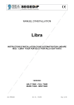
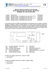
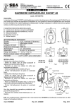
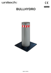
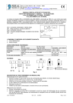
English
INFRARED BEAM PHOTOCELL FT30AV
General
The photoelectric barrier FT30AV has been projected for applications in which it is necessary to apply two overlapping photocells,
avoiding that they go in collision one with the other. To get such result it is sufficiant to power supply the photocells with 12/24 V~ and
to cross the power supply. (Ex. When the TX and RX of a photocell are power supplied with a black cable around 0 V~ and with a red
cable of 24V~, the TX and the RX of the other photocell will have to have the red cable with 0 V~ and the black cable around 24
V~.)
The Photocell Kit Consists of:
1 No. Photocell Receiver
1 No. Photocell Transmitter
1 No. Fixing Kit
4 No. cover-screw cap
1 No. Set of fitting instructions
* The range of the device can be reduced in case
of bad weather conditions (fog, rain, etc..).
Technical Characteristics
Nominal range:
Signal:
Wave length:
Modulation Frequency:
Supply Voltage:
Absorbed Current:
Temp. Operating Range:
Relay Contact Rating:
Humidity:
30 m*
Modulated infrared
880 nm
1000 Hz
12 - 24 V / V~
30mA TX; 30mA RX
-15° C / +60° C
1A max; 24V
from 5% to 90% no
condensation
INSTALLATION
Transmitter
-Insert the cables in the special seat and make the connections according to the type of application, 12 or 24V~ or V
or not synchronized.
-Adjust the cable within the unit to eliminate any surplus.
-Fix the unit.
-Seal the cover & cable entry to prevent insect infestation.
, synchronized
Receiver
-Insert the cables into the special seat and make the connections accoriding to the type of application chosen for the transmitter, 12/
24V~ or V
, synchronized or not synchronized.
-Adjust the cable within the unit to eliminate any surplus.
-Make sure that the receiver is in frontal position, lined up on the same axis and in the same height of the associated transmitter. Act
on the lens adjustment if necessary (see fig.6-7).
-Seal the cover & cable entry to prevent insect infestation.
Once executed the preceding operations for both Tx and for Rx:
-Power supply the photocells 12-24V~ or V
and verify their alignment. If the positioning, the alignment and the connection of the
photocells are correct, the red LED on the receiver will be switched on.
Please note: For the syncronized function, the power supply has to be necessarily of 12/24 V~ (alternating current).
Operational Verification
Fit one of the black plastic photocell covers complete with an opaque diffuser label stuck across the lens.
- Check that the relay works correctly.
- Check that the red led goes out when the beam is broken.
Red led Function:
RED LED LIT: ALIGNED
YELLOW LED ON: NOT ALIGNED OR BAD ALIGNMENT
SECURITY
The 23102160 device cannot be used as security device (EN 12978).
SPARE PARTS
To obtain spare parts contact: Prastel France.
INTENDED USE
The photocell 23102160 has been projected to be used exclusivley as photoelectric barrier to be installed in the areas considered
dangerous and in proximity of the gate/ leaf, it must be used exclusively for the functioning as interposition between transmitter and
receiver (installed according to the above mentioned instructions) and must be power supplied with safety tension.
ENVIRONMENT
Please dispose of this product packaging in a responsible, appropriate way.
CONFORMITIES
The 23102160 photocell conforms to the following: 2004/108/CE (Act on the Electromagnetic Compatibility)
Correct Disposal of This Product (Waste Electrical & Electronic Equipment) - Europe only
(Applicable in the European Union and other European countries with separate collection systems)
This marking shown on the product or its literature, indicates that it should not be disposed with other household wastes
at the end of its working life. To prevent possible harm to the environment or human health from uncontrolled waste disposal, please
separate this from other types of wastes and recycle it responsibly to promote the sustainable reuse of material resources.
67411400P
Rev. 02 - 05/2013
Pag. 1
English
Household users should contact either the retailer where they purchased this product, or their local government office, for details of
where and how they can take this item for environmentally safe recycling.
STORING
STORAGE TEMPERATURES
Tmax
Humiditymin
+70 °C
5% no condensation
Tmin
-20 °C
Humiditymax
90% no condensation
When being transported this product must be properly packaged and handled with care
CLEANING AND MAINTENANCE
Cleaning and maintenance of this unit must be carried out at 6 monthly intervals by authorised, qualified personnel. During routine
maintenance the following checks should be made: Correct alignment, sealing, cleanliness of the lenses and internal components.
Any remedial work should be carried out as required.
DECOMMISSIONING
If the 23102160 photocell is to be taken out of service, this work must only be undertaken by authorised, qualified personnel.
NOTE: THE MANUFACTURER CAN NOT BE DEEMED RESPONSIBLE FOR ANY DAMAGE OR INJURY CAUSED BY
IMPROPER USE OF THIS PRODUCT.
Prastel France reserves the right to do changes or variations that may be necessary to its products with no obligation to notice.
Fig. 2
32
JP1
17 mm
32
Tx1
JP1
Fig. 1
Fig. 3
Rx1
000
ON/OFF
1
2 3
1
2
3
4
5 6
29 mm
JP1
1
Note : The control for alignment with the tester is possible
for a distance of up to max.20m.
JP1
Rx2
Tx2
2 3
1
2
3
HOLD
4
The measured
voltage value
depends on the
distance between
TX and RX, and
must always be
between a
minimum of
200mV and a
maximum of 6V.
Remove the
protective film
after installation.
5 6
JP1 ON = SYNCRONIZATION ACTIVATED
JP1 OFF = SYNCRONIZATION NOT ACTIVATED
Fig. 4
Fixing screw for horizontal alignment Use Ph2 type screwdrive
Operation with
aligned positioning
Operation with non
aligned positioning
Fixing screws for
vertical alignment Use Ph1 type screwdrive
To be tightened after
installation is completed
Fig. 5
Fig. 7
30°
Fig. 6
Rev. 02 - 05/2013
Pag. 2
Français
BARRIERE INFRAROUGE FT30AV
Information
La barrière infrarouge FT30AV a été créé pour des installations dans lesquelles il est nécessaire d'appliquer deux cellules
superposées, sans qu ’elles ne se perturbent. Pour cela, il suffit d'alimenter les photocellules avec une alimentation de 12/24 V~ et
de croiser les alimentations (Ex. Si TX et RX d'une photocellule sont alimentés avec un câble de couleur noire de 0 V~ et avec un
câble de couleur rouge de 24V~, le TX et RX de l'autre photocellule devront avoir le câble de couleur rouge à 0 V~ et le câble de
couleur noire à 24 V~).
Caracteristiques techniques
Portée nominale:
30 m*
Signal:
infrarouge modulé
Longueur d'onde:
880 nm
Fréquence infrarouge: 1000 Hz
Alimentation:
12 - 24 V
/ V~
* La portée de l'appareil peut être réduite
30 mA TX; 30 mA RX
en cas de mauvaises conditions météorologiques Absorption:
(brouillard, pluie, etc.).
Temp. de fonction.:
- 15 °C / + 60 °C
Contacts relais:
1A max @ 24V
INSTALLATION
Humidité:
de 5 % à 90 % sans condensation
L'ensemble comprend les éléments suivants:
N. 1 cellule photo-éléctrique réceptrice
N. 1 cellule photo-éléctrique émettrice
N. 1 kit pour la fixation
N. 4 bouchon couvre-vis
N. 1 Mode d'emploi
Barrière infrarouge émettrice
-Connecter les câbles d ’alimentation dans le bornier en respectant 12 / 24V et sélectionner le cavalier (JP1) synchronisée ou pas.
-Placer les câbles de façon à ne pas occulter le rayon infrarouge.
-Refermer les capots.
- Fermer hermetiquement la gaine et les eventuels trous qui pourraient acheminer des corps étrangers à l’intérieur de la cellule.
Barrière infrarouge réceptrice
-Connecter les câbles d ’alimentation dans le bornier en respectant 12 / 24V et sélectionner le cavalier (JP1) synchronisée ou pas.
-Placer les câbles de façon à ne pas occulter le rayon infrarouge.
-Fixer le Récepteur et aligner le sur le même axe et la même hauteur que l ’émetteur. Agir sur le réglage de la lentille
si nécessaire (voir fig.6-7).
- Fermer hermetiquement la gaine et les eventuels trous qui pourraient acheminer des corps étrangers à l’intérieur de la cellule.
-Alimenter les barrières infrarouge 12 - 24 V.
Si le positionnement, l'alignement et la liaison de la photocellule sont exécutés correctement, la LED rouge sur le récepteur sera
allumée.
ATTENTION: Pour avoir la fonction synchronisée, l'alimentation doit être obligatoirement de 12 / 24 V~ (courant alternatif).
Opérations de contrôle
Contrôler plusieurs fois, en interrompant le faisceau infrarouge au moyen d'un carton noir. Chaque fois que le rayon est interrompu,
la LED rouge doit s'éteindre.
Fonctionnement du LED rouge
LED ROUGE ALLUMEE: ALIGNEE
LED JAUNE ALLUMEE: PAS ALIGNEE OU MAUVAIS ALIGNEMENT
SECURITES
Le dispositif 23102160 ne peut pas être utilisé comme dispositif de sécurité (EN 12978).
PIECES DE RECHANGE
Les demandes de pièces de rechange sont à adresser à: Prastel France.
UTILISATION
Le dispositif 23102160 a été étudié pour l'utilisation exclusive comme barrière infrarouge à disposer dans les zones dangereuses et
en proximité du portail/vantail; l'utilisation de cette barrière est prevue exclusivement comme interposition parmi l'émetteur et le
récepteur (installés selon les instructions précédentes) et son alimentation doit être à une tension de sécurité.
SECURITE ET COMPATIBILITE DE L'ENVIRONNEMENT
Ne pas disperser dans l'environnement les materiaux de l'emballage et/ou les circuits.
CONFORMITE
Le dispositif 23102160 est conforme aux normes : 2004/108/CE (Directive sur la compatibilité électromagnetique)
Comment éliminer ce produit (déchets d'équipements électroniques) - Europe uniquement
(Applicable dans les pays de l'Union Européen et aux autres pays européens disposant de systémes de collecte
sélective)
Ce symbole sur le produit ou sa documentation indique qu'il ne doit pas être jeté avec les autres déchets ménagers.
L'élimination des déchets pouvant porter préjudice à l'environnement ou à la santé humaine, veuillez le séparer des autres types de
déchets et le recycler de façon responsable. Vous favoriserez ainsi la réutilisation durable des ressources
Rev. 02 - 05/2013
Pag. 3
Français
matérielles. Les particuliers sont invités à contacter le distributeur leur ayant vendu le produit ou à se renseigner auprès de leur
mairie pour savoir où et comment ils peuvent se débarrasser de ce produit afin qu'il soit recyclé en respectant l'environnement.
STOCKAGE
TEMPERATURES DE STOCKAGE
TMax
Humidité min
5% sans condensation
+ 70°C
Tmin
- 20°C
HumiditéMax
90% sans condensation
NETTOYAGE ET MAINTENANCE
Les interventions de nettoyage et maintenance doivent être réalisées seulement et exclusivement par une personne qualifiée
chaque six mois en vérifiant: l'alignement parmis l'émetteur et le récepteur, la tenue des systèmes de fixation, le nettoyage de la
lentille, le nettoyage des parties intérieures de la cellule etc.
MISE HORS SERVICE
La désinstallation et/ou la mise hors service du dispositif 23102160 doivent être réalisées exclusivement par une personne
qualifiée.
N.B. LE CONSTRUCTEUR N'EST PAS RESPONSABLE DE DOMMAGES EVENTUELS A LA SUITE D'UNE UTILISATION
IMPROPRE, ERRONNEE OU IRRAISONABLE.
Prastel France se réserve le droit de faire des modifications sur ces produits et/ou pour le présent manuel sans aucune obligation
de préavis.
Fig. 2
32
JP1
17 mm
32
Tx1
JP1
Fig. 1
Fig. 3
Rx1
000
ON/OFF
1
2 3
1
2
3
4
5 6
29 mm
JP1
1
ATTENTION : la vérification de l ’alignement avec le tester
est possible jusqu ’à une distance maximale de 20m.
JP1
Rx2
Tx2
2 3
1
2
3
HOLD
4
La valeur de la
tension mesurée
dépend de la
distance entre TX
et RX, et doit
toujours être
compris entre un
minimum de
200mV et un
maximum de 6V.
Retirez le film
de protection
après l'installation.
5 6
JP1 ON = SYNCHRONISATION ACTIVE
JP1 OFF = SYNCHRONISATION PAS ACTIVE
Fig. 4
Vis de fixation pour l’alignement horizontal Utilisez un tournevis du type Ph2
Fonctionnement avec
positionnement axé
Fonctionnement avec
positionnement desaxé
Vis de fixation pour
l’alignement vertical Utilisez un tournevis
du type Ph1
A serrer une fois que
l’installation est terminée
Fig. 5
Fig. 7
30°
Fig. 6
Rev. 02 - 05/2013
Pag. 4