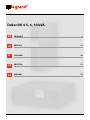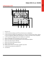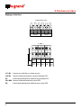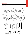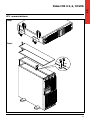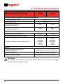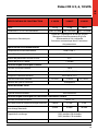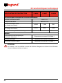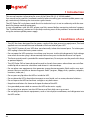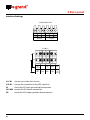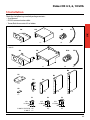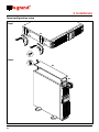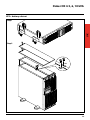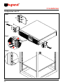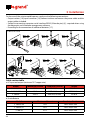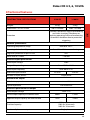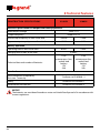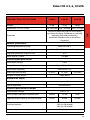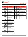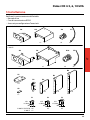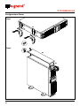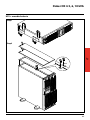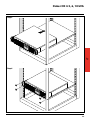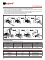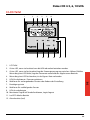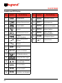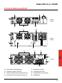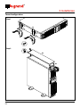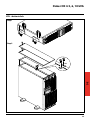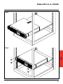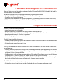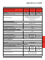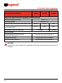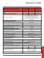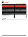
1
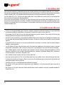
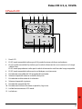
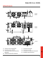
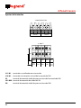
®
Daker DK 4.5, 6, 10 kVA
Manuel d’installation • Installation manual
Part. LE05380AB-07/12-01 GF
®
Daker DK 4.5, 6, 10 kVA
2
fr
français
uk
fr
english
21
IT
ITALIANO
39
DE
DEUTSCH
57
ES
ESPAÑOL
75
3
FR
Daker DK 4.5, 6, 10 kVA
Indice
1 Introduction
4
2 Conditions d’utilisation
4
3 Panneau LCD
5
4 Panneau arrière
7
5 Installation
9
6 Logiciel d’autodiagnostic ups communicator
16
7 Dysfonctionnements possibles
16
8 Caractéristiques techniques
17
3
®
1 Introduction
Ce manuel contient les informations concernant l’utilisation des modèles Daker DK 4.5, 6, 10 kVA.
Il est recommandé de lire attentivement ce manuel avant de procéder à l’installation de l’onduleur
et de respecter scrupuleusement les instructions ci-dessous.
Les UPS Daker DK 4.5, 6, 10 kVA sont conçus pour une utilisation civile ou industrielle.
Ils ne sont pas conformes aux réglementations pour appareils électriques médicaux.
En cas de problème sur l’UPS, il est recommandé de lire le présent manuel avant de contacter le
service d’assistance technique ; la section “Éventuels problèmes et solutions” permet en effet de
résoudre la plupart des problèmes rencontrés durant l’utilisation du groupe de continuité.
2 Conditions d’utilisation
• L’UPS est conçu pour alimenter des appareillages de traitement de données ; la charge appliquée
ne doit pas dépasser celle indiquée sur l’étiquette apposée au dos de l’UPS.
• Le bouton ON/OFF de l’UPS n’isole pas électriquement les parties internes. Pour isoler l’UPS, le
débrancher de la prise d’alimentation du secteur.
• Ne pas ouvrir le conteneur de l’UPS car des parties peuvent être sous tension dangereuse à l’intérieur, même si la prise du secteur est débranchée. Dans tous les cas, à l’intérieur de l’onduleur,
aucune pièce ne peut être réparée par l’utilisateur.
• Le panneau frontal de contrôle est prévu pour des opérations manuelles ; ne pas appuyer sur le
panneau avec des objets pointus ou coupants.
• Les UPS Daker DK ont été conçus pour fonctionner dans un environnement fermé, propre, sans
liquide inflammable ou substances corrosives et non excessivement humide.
• Ne pas positionner l’onduleur à proximité d’appareils qui génèrent de forts champs électromagnétiques et/ou d’appareils sensibles aux champs électromagnétiques (moteurs, disquettes,
haut-parleurs, transformateurs, écrans, video, etc...).
• Ne pas verser de liquides sur ou dans l’UPS.
• Éviter d’exposer l’UPS à la lumière directe du soleil ou à proximité de sources de chaleur.
• Maintenir toujours propres les fentes d’aération et ne pas les obstruer afin de permettre la dissipation de la chaleur interne de l’UPS.
• Brancher l’UPS à une installation équipée d’un conducteur de mise à la terre.
• Ne pas utiliser l’UPS pour alimenter des imprimantes laser à cause de leur courant de démarrage
élevé.
• Ne pas utiliser l’UPS pour alimenter des électroménagers comme les sèche-cheveux, les climatiseurs, les réfrigérateurs, etc.
4
FR
Daker DK 4.5, 6, 10 kVA
3 Panneau LCD
1
3
4
2
5
9
11
10
12
8
6
7
1.
Panneau LCD
2.
Le LED vert allumé indique que l’UPS peut fonctionner en redondance.
3.
Le LED vert allumé indique que l’alimentation sur secteur est comprise entre 160 et 288 Vca.
Le LED vert clignotant indique que l’alimentation sur secteur est hors des limites acceptables.
4.
Le LED vert allumé indique que le réseau de By-pass est présent.
5.
Bouton d’allumage UPS/Désactivation avertisseur sonore
6.
Bouton de sélection de la page précédente ou de changement réglage
7.
Bouton de confirmation de sélection
8.
Bouton de sélection de la page suivante
9.
Bouton d’extinction UPS
10. Bouton menu d’accès aux fonctions spéciales, log in/out
11. Led de fonctionnement en modalité ECO
12. Led d’alarme
5
®
EPO
Er05
Symboles écran LCD
Réf.
Symbole
Description
Réf.
Symbole
Er06
1
LINE
Alimentation sur secteur
17
Er10
Courant excessif
variateur fréquence
2
Niveau batterie fiable
18
Er11
Surchauffe
3
Batterie endommagée
19
Er12
Surcharge en sortie
4
Surcharge
20
Er14
Ventilateurs défectueux
5
Fonctionnement en
Service Mode
21
Er15
Erreur procédure
“Mode Maintenance”
6
Blackout en sortie UPS
22
Er28
By-pass prolongé
7
Ligne By-pass hors
tolérance
23
Er**
Autres alarmes
8
Secteur d’alimentation
hors tolérance
9
OFF
UPS éteint
10
LINE OFF Extinction anormale
11
Schéma de
fonctionnement UPS
12
Visualisation mesures
13
Indique le paramètre
mesuré
14
EPO
Extinction EPO
15
Er05
Batterie faible
ou à changer
16
Er06
Court-circuit en sortie
Er10
6
3 Panneau LCD
Er11
Description
FR
Daker DK 4.5, 6, 10 kVA
4 Panneau arrière
14
19
15
RS232
13
EPO
Parallel Work Comm.
Bus Not Intended to
TNV Communication Network
OUTPUT
OFF
S1
ON
Ext. Battery
G2
N22
G1
N1
3 100 56
3 100 57
L12
G
+
CB1
Utility Input
Breaker
16
20
17-18
20
17-18
16
19
Ext.
Battery
-
UTILITY
INPUT
BREAKER
EPO
G
+
14
CH B
SLOT
3 100 58
S1
RS232
BYPASS
INPUT
BREAKER
Not Intended to
TNV Communication
Network
ON OFF
US 6906501, TW 202668
19
20
13
3 100 53
3 100 54
PAT. NO.:
G1
INPUT
N1 L12
14
OUTPUT
G2 N22 L21
Utility Input
Breaker
EPO
Slot
15
L21-N22: UPS OUTPUT L12-N1: UTILITY INPUT
G2: OUTPUT EARTH G1:
INPUT EARTH
GROUND
GROUND
Parallel Work Comm.
Bus Not Intended to
TNV Communication Network
RS232
13
INPUT
L21
-
TB1
15
TB2
17-18
13. Port de communication RS232
17. Connexions d’entrée
14. Coupure d’urgence alimentation (EPO)
18. Connexions de sortie
15. L ogement pour cartes
de communication en option
19. Interrupteurs de protection d’entrée
16. Connecteur expansion autonomie
20. Ventilateurs de refroidissement
7
®
4 Panneau arrière
Réglages Interface
3 100 53/54/55/56
OUTPUT
G2 N22 L21
G1
INPUT
N1 L12
L21-N22: UPS OUTPUT L12-N1: UTILITY INPUT
G2: OUTPUT EARTH G1:
INPUT EARTH
GROUND
GROUND
3 100 57
TB1
TB2
TB1
OUTPUT
TB2
INPUT
G2
G1
N1
N22
L21
UTILITY
BYPASS
L12
L11-N1 : bornes non utilisées sur cette version
L12-N1 : bornes de branchement au réseau d’entrée UPS
G1 : borne de branchement câble de terre entrée UPS
L21-N22 : bornes de branchement de sortie UPS
G2 : 8
borne de branchement câble de terre sortie UPS
L11
DIM ONLY
FR
Daker DK 4.5, 6, 10 kVA
5 Installation
Contrôler le contenu de l’emballage :
• Mode d’emploi
• Câble de communication RS232
• Accessoires de configuration Tower/rack
3 100 53/54/55/56
A4
A5
x1
A6
x1
A7
x2
x2
3 100 57
A8
A9
x1
A10
x1
x2
A7
x2
B4
A1
B3
B1
B2
x4
A3
x2
x2
x2
x2
x1
S1
6.0
±1.0mm
M3
3 100 53/54/55/56 x6
3 100 57 x7
S2
6.0
±1.0mm
S3
8.0
±1.0mm
M3
M4
x8
x6
9
®
5 Installation
Configuration tower
Step 1
A1
A1
A1
A1
Step 2
A3
A2
10
FR
Daker DK 4.5, 6, 10 kVA
Ups + armoire batterie
Step 1
Step 2
A4
11
®
5 Installation
Configuration rack 19”
Step 1
B1
S3
Step 2
Step 3
90°
Step 4
12
B2
FR
Daker DK 4.5, 6, 10 kVA
Step 5
Step 6
13
®
5 Installation
Au dos du groupe de continuité sont prévus les branchements suivants :
• Prises de sortie [19] et connecteur d’entrée [18] : à ces deux connecteurs, brancher le câble
d’alimentation et les câbles de sortie fournis à cet effet.
• Prise de branchement interface sérielle de l’ordinateur type RS232 (9 pôles femelle) [4] : à utiliser
dans le cas où l’on souhaiterait utiliser le logiciel de diagnostic et gestion extinction.
• Connexion prévue pour batteries supplémentaires [17].
3 100 53/54/55/56
A7
S1
A6
S1
A5
A4
S1
60 - 70
3 100 57
A7
S1
S1
A9
A10
A8
S1
Tableau section câbles
a. Entrée et sortie CA (câble en cuivre minimum 75°C)
Modèle
Courant maximum
Section conducteur
Force de torsion
3 100 53/56
25 A
2
AWG #10/4 mm
17,7/ 11 lb-in
3 100 54/57
33 A
2
AWG # 8/6 mm
17,7/ 11 lb-in
3 100 58
54,3 A
AWG # 6/10 mm2
23 lb-in
b. Entrée Batterie
14
Modèle
Courant maximum
Section conducteur
3 100 53/56
19 A
AWG #10/4 mm2
3 100 54/57
25 A
AWG #10/4 mm2
3 100 58
41 A
AWG #10/4 mm2
FR
Daker DK 4.5, 6, 10 kVA
AVERTISSEMENT
Pour des raisons de sécurité, il est recommandé de ne pas modifier les câbles fournis ; en
outre, il est nécessaire de s’assurer que le prise de secteur à laquelle le groupe de continuité
est branché dispose d'une bonne connexion au circuit de terre comme requis par la norme.
AVERTISSEMENT
La prise d’alimentation sur secteur ou le dispositif de sectionnement doit être installé à
proximité de l’appareillage et doit être facile d’accès.
Procéder à l’installation comme suit :
1) Positionner le groupe de continuité de telle sorte que les fentes de ventilation ne soient pas
obstruées.
2) Au connecteur d’entrée [18], brancher le câble d’alimentation et les câbles de sortie aux
connecteurs correspondants [19].
3) Brancher les charges aux câbles de sortie en s’assurant que les interrupteurs des différents
dispositifs sont sur la position Off.
4) Brancher la fiche d’alimentation à une prise de courant adaptée à la tension et au courant requis.
Allumage
1) Allumer le groupe de continuité à l’aide du bouton prévu à cet effet [7] en le maintenant
enfoncé pendant 3 secondes environ jusqu’à ce que l’UPS émette un signal sonore ; ensuite, les
, et
s’allument au bout de 30 secondes environ.
leds LINE ,
2) Allumer les charges et s'assurer de l'absence de signaux d'alarme.
3) Il est recommandé d’effectuer une commutation sur batteries, en coupant l'alimentation
sur secteur, avant de brancher les charges critiques à l’UPS pour s’assurer que les batteries
fonctionnent correctement.
Extinction
OFF sur le bouton d’extinction [8] en le maintenant enfoncé pendant 5 secondes environ
1) Appuyer
FAIL
jusqu’à
ce que l’UPS émette un signal sonore. L'UPS coupe l’alimentation sur les connecteurs
de sortie. Tous les LEDs s’éteignent mais les ventilateurs continuent à fonctionner tant que
l’alimentation sur secteur est présente.
Connexion
Er05
L’UPS est doté d’une interface de communication sérielle RS232 grâce à laquelle il est possible
d'accéder,Er06
par l’intermédiaire d’un ordinateur, à une série de données relatives au fonctionnement
Er10
et à l’historique
de l’UPS. La fonction est utilisable par l’intermédiaire du programme d’interface
pour WINDOWS
(*), en connectant un port sériel du PC au prise d’interface présent au dos de
Er11
l’UPS, à l’aide
d’un
câble RS 232.
Er12
Er**
15
®
6 Logiciel d’autodiagnostic ups communicator
Sur le site www.ups.legrand.com, il est possible de télécharger gratuitement un logiciel d’autodiagnostic pour WINDOWS (16 et 32 bits) et Linux.
Ce logiciel fournit les fonctions suivantes :
- Visualisation de toutes les données de fonctionnement et de diagnostic en cas de problème.
- Configuration des fonctions spéciales.
- Extinction automatique de l’ordinateur local (avec logiciel d’exploitation Windows et Linux).
* Windows est une marque enregistrée de Microsoft Corporation.
7 Dysfonctionnements possibles
L’UPS marche toujours avec alimentation batterie :
• la tension de secteur n’est pas présente ;
• la tension de secteur est hors des limites de la plage de l’UPS ;
• le câble d’alimentation n’est pas correctement branché à la prise d’alimentation.
• l’interrupteur magnétothermique est en position relevée.
• la prise d’alimentation est défectueuse.
L’UPS signale une surcharge :
• des charges supplémentaires, en plus de celles normalement connectées, ont été involontairement
branchées ;
• vérifier toutes les charges branchées en sortie.
L’UPS ne fonctionne pas avec alimentation batterie (il se bloque ou signale immédiatement une
réserve autonomie):
• l’UPS a marché pendant longtemps sans alimentation de secteur et n’a pas pu recharger sa
batterie. La recharger pendant au moins 6 heures en branchant l’onduleur à l’alimentation
secteur, allumé.
• la batterie est déchargée à cause d’une longue période d’inactivité de l’UPS. La recharger
pendant au moins 6 heures en branchant l’onduleur à l’alimentation secteur.
• la batterie s’est épuisée à cause de son utilisation fréquente, des conditions environnementales
ou du dépassement de la durée moyenne de vie, elle doit être remplacée.
L’UPS ne fournit pas de tension en sortie:
• vérifier que les charges sont correctement branchées aux prises de sortie.
16
FR
Daker DK 4.5, 6, 10 kVA
8 Caractéristiques techniques
Spécifications de construction
Poids
Dimensions L x H x P en millimètres
Protections électroniques
3 100 53
3 100 54
52 Kg
52 Kg
440 x 176 x 680
440 x 176 x 680
Contre les surcharges et les courts-circuits
Blocage du fonctionnement dû à la fin
d’autonomie et à la surchauffe
Extinction automatique due à l’activation
des protections
Spécifications environnementales
Température de fonctionnement
Humidité relative pour le fonctionnement
de 0 à +40 °C
de 20 à 80% sans condensation
Niveau de protection suivant IEC529
IP21
Niveau de bruit à 1 mètre
< 50 dBA
Caractéristiques électriques d’entrée
Tension nominale d’entrée
230 V
Tension d’entrée
de 160 V à 288 V
Fréquence nominale d’entrée
50 ou 60 Hz ± 5%
Courant maximum d’entrée
25 Arms
Nombre des phases d’entrée
33 Arms
monophasé
Forme d’onde de sortie
Avec fonctionnement batterie
sinusoïdale
Type de fonctionnement
line interactive
Caractéristiques électriques de sortie avec alimentation secteur
Tension nominale de sortie
230 V ± 1%
Puissance active de sortie avec charge nominale
4,05kW
5,4 kW
Puissance apparente de sortie
avec charge nominale
4,5kVA
6 KWA
Capacité de surcharge
Nombre des phases de sortie
105% continuativo
120% per 30 secondi
140% per 10 secondi
monophasé
17
®
8 Caractéristiques techniques
Spécifications de construction
3 100 53
3 100 54
Caractéristiques électriques de sortie avec alimentation
Tension nominale de sortie
230 V ± 1%
Fréquence de sortie
50/60 Hz ± 5%
Puissance active de sortie
sur charge non linéaire
4,05kW
5,4kW
Puissance apparente de sortie
sur charge non linéaire
4,5kVA
6kVA
6 min.
4 min.
Fonctionnement avec batterie
Autonomie à 80% de la charge
Temps de recharge à 90% de la charge
Données techniques et quantité de batteries
4 heures
20 sans
entretien,
au plomb,
scellée
12V 5Ah
20 sans
entretien,
au plomb,
scellée
12V 5Ah
Normes
Compatibilité électromagnétique
immunité - émissions
Répondant aux normes EN 62040 - 2
Sécurité électrique
Répondant aux normes EN 62040-1
Prestations caractéristiques
Répondant aux normes EN 62040 -3
ATTENTION
Les batteries sont considérées comme des déchets dangereux et doivent être éliminées
suivant la réglementation en vigueur.
18
FR
Daker DK 4.5, 6, 10 kVA
Spécifications de construction
Poids
Dimensions L x H x P en millimètres
Protections électroniques
3 100 56
3 100 57
3 100 58
25 Kg
25 Kg
26 Kg
440 x 88 x 680
440 x 88 x 680
440 x 132 x 680
Contre les surcharges et les courts-circuits
Blocage du fonctionnement dû à la fin
d’autonomie et à la surchauffe
Extinction automatique due à l’activation
des protections
Spécifications environnementales
Température de fonctionnement
Humidité relative pour le fonctionnement
de 0 à +40 °C
de 20 à 80% sans condensation
Niveau de protection suivant IEC529
IP21
Niveau de bruit à 1 mètre
< 50 dBA
Caractéristiques électriques d’entrée
Tension nominale d’entrée
230 V
Tension d’entrée
de 160 V à 288 V
Fréquence nominale d’entrée
50 ou 60 Hz ± 5%
Courant maximum d’entrée
25 Arms
Nombre des phases d’entrée
33 Arms
54,3 Arms
monophasé
Forme d’onde de sortie
Avec fonctionnement batterie
sinusoïdale
Type de fonctionnement
line interactive
Caractéristiques électriques de sortie avec alimentation secteur
Tension nominale de sortie
230 V ± 1%
Puissance active de sortie avec charge nominale
4,05kW
5,4 kW
9 kW
Puissance apparente de sortie
avec charge nominale
4,5kVA
6 KWA
10 KWA
Capacité de surcharge
Nombre des phases de sortie
105% sans interruption
120% pendant 30 secondes
140% pendant 10 secondes
monophasé
19
®
8 Caractéristiques techniques
Spécifications de construction
3 100 56
3 100 57
3 100 58
Caractéristiques électriques de sortie avec alimentation
Tension nominale de sortie
230 V ± 1%
Fréquence de sortie
50/60 Hz ± 5%
Puissance active de sortie
sur charge non linéaire
4,05kW
5,4kW
9kW
Puissance apparente de sortie
sur charge non linéaire
4,5kVA
6kVA
10kW
Temps de recharge à 90% de la charge
4 heures
5 heures
Normes
Compatibilité électromagnétique
immunité - émissions
Répondant aux normes EN 62040 - 2
Sécurité électrique
Répondant aux normes EN 62040-1
Prestations caractéristiques
Répondant aux normes EN 62040 -3
ATTENTION
Les batteries sont considérées comme des déchets dangereux et doivent être éliminées
suivant la réglementation en vigueur.
20
Daker DK 4.5, 6, 10 kVA
1 Introduction
22
2 Conditions of use
22
3 LCD Panel
23
4 Rear panel
25
5 Installation
27
6 UPS communicator self-diagnostic software
34
7 Possible malfunctioning
34
8 Technical features
35
21
UK
Index
®
1 Introduction
This manual contains information for users of the Daker DK 4.5, 6, 10 kVA models.
You are advised to read this handbook carefully before installing your uninterruptible power supply, meticulously following the instructions given herein.
The UPS Daker DK is only been made for civil or industrial use; it is not in conformity with the standards for electro-medical equipment.
In case of problems with the UPS, please read this manual before contacting technical support;
The “Troubleshooting” section can in fact help resolving most of the problems encountered while
using the uninterruptible power supply.
2 Conditions of use
• The UPS has been designed for the power supply of the data processing equipment; The load
applied must not exceed the one indicated on the rear label of your UPS.
• The ON/OFF button of your UPS does not electrically isolate the internal parts. To isolate your
UPS unplug it from the mains power socket.
• Do not open the UPS container since there may be parts inside with dangerously high voltage
even when the mains plug is disconnected; there are no parts inside that the user can repair.
• The front control panel is provided for manual operations; Do not press on the panel with sharp
or pointed objects.
• The UPS Daker DK has been designed to work in closed, clean rooms where there are no inflammable liquids or corrosive substances and where it is not too damp.
• Do not place near equipments that generate strong electro-magnetic fields and/or near equipments that are sensible to electro-magnetic fields. (engines, floppy disks, speakers, adapters,
monitors, video, etc...)
• Do not pour any liquid on the UPS or inside the UPS.
• Do not place the UPS in humid environment or near liquid, such as water, chemical solution…
• Do not expose the UPS to the direct sunlight or any heat sorces.
• Keep the ventilation slits clean to dissipate the heat of the UPS.
• Use grounded power cable to connect the UPS to the mains supply.
• Do not plug laser printers into the UPS because of their high start-up current.
• Do not plug house electric equipments, such as hair dryer,air conditioner, and refrigerator into
the UPS outlets.
22
Daker DK 4.5, 6, 10 kVA
3 LCD Panel
3
4
2
11
12
UK
1
5
9
10
8
6
7
1. LCD panel
2. Green LED indicates that the UPS is able to run under redundancy mode.
3. Solid green LED indicates that the utility input voltage is within the window.
Flashing green LED indicates that the utility input voltage is outside the acceptable window.
4. Green LED indicates that Bypass Input is normal.
5. UPS ON/Alarm Silence
6. Go to previous page or change the setting of the UPS.
7. Confirm a changed setting.
8. Go to the next page.
9. UPS OFF Switch
10. Special functions log in/out
11. UPS is working under ECO (Economical) mode.
12. UPS alarm LED
23
®
EPO
Er05
Display LCD symbols
Item
Symbol
Er06
Utility or Bypass Source
17
Er10
Inverter Over-current
2
Battery Low
18
Er11
The UPS is overheated
3
Battery Abnormal
19
Er12
UPS Output Overloading
4
UPS Overloading
20
Er14
Fan Error
5
UPS Working
in specified mode*
21
Er15
Wrong Procedure to
Enter Maintenance Mode
6
A Blackout Transfer
occurred in UPS Output
22
Er28
Bypass Overload
Time out
7
Bypass Input Abnormal, UPS
fails to transfer to bypass
23
Er**
Other Error code
8
Utility Input Abnormal
Item
Symbol
1
LINE
9
10
OFF
Description
UPS Shutoff
LINE OFF UPS Abnormal Lock
11
UPS Flow Chart
12
4-Digit Measurement
Display
13
Indicates the item
to be measured
14
EPO
Emergency Power Off
15
Er05
Battery Weak or Dead
16
Er06
Output Short Circuit
Er10
24
3 LCD Panel
Er11
Description
Daker DK 4.5, 6, 10 kVA
4 Rear panel
14
19
15
RS232
13
EPO
Ext. Battery
G2
N22
G1
N1
3 100 56
3 100 57
L12
G
+
CB1
Utility Input
Breaker
16
20
17-18
20
17-18
16
19
Ext.
Battery
-
UTILITY
INPUT
BREAKER
EPO
G
+
14
CH B
SLOT
3 100 58
S1
RS232
BYPASS
INPUT
BREAKER
Not Intended to
TNV Communication
Network
ON OFF
US 6906501, TW 202668
19
20
13
3 100 53
3 100 54
PAT. NO.:
G1
INPUT
N1 L12
14
OUTPUT
G2 N22 L21
Utility Input
Breaker
EPO
Slot
15
L21-N22: UPS OUTPUT L12-N1: UTILITY INPUT
G2: OUTPUT EARTH G1:
INPUT EARTH
GROUND
GROUND
Parallel Work Comm.
Bus Not Intended to
TNV Communication Network
RS232
13
INPUT
L21
-
UK
Parallel Work Comm.
Bus Not Intended to
TNV Communication Network
OUTPUT
OFF
S1
ON
TB1
15
TB2
17-18
13. RS-232 Port
17. AC utility power connection
14. E mergency Power Off (EPO) Dry Contact
Signal inputs
18. AC Outlets power connection
15. Communication Card Options Slot
20. Cooling Fans
16. External Battery Connector
19. Utility Input circuit breaker
25
®
4 Rear panel
Interface Settings
3 100 53/54/55/56
OUTPUT
G2 N22 L21
G1
INPUT
N1 L12
L21-N22: UPS OUTPUT L12-N1: UTILITY INPUT
G2: OUTPUT EARTH G1:
INPUT EARTH
GROUND
GROUND
3 100 57
TB1
TB2
TB1
OUTPUT
TB2
INPUT
G2
G1
N1
N22
L21
UTILITY
BYPASS
L12
L11-N1 : clamps not used in this version
L12-N1 : clamps for connection to the UPS input line
G1: clamp for UPS input ground cable connection
L21-N22: clamps for UPS output connection
G2: 26
clamp for UPS output ground cable connection
L11
DIM ONLY
Daker DK 4.5, 6, 10 kVA
5 Installation
Check for the following standard package contents:
• User Manual
• RS-232 communication cable
• Tower/Rack Accessories Kit as below:
3 100 53/54/55/56
A5
A6
A7
UK
A4
x1
x1
x2
x2
3 100 57
A8
A9
x1
A10
x1
x2
A7
x2
B4
A1
B3
B1
B2
x4
A3
x2
x2
x2
x2
x1
S1
6.0
±1.0mm
M3
3 100 53/54/55/56 x6
3 100 57 x7
S2
6.0
±1.0mm
S3
8.0
±1.0mm
M3
M4
x8
x6
27
®
5 Installation
Tower configuration setup
Step 1
A1
A1
A1
A1
Step 2
A3
A2
28
Daker DK 4.5, 6, 10 kVA
UPS + battery cabinet
UK
Step 1
Step 2
A4
29
®
5 Installation
Configuration rack 19”
Step 1
B1
S3
Step 2
Step 3
90°
Step 4
30
B2
Daker DK 4.5, 6, 10 kVA
UK
Step 5
Step 6
31
®
5 Installation
On the rear of the uninterruptible power supply are the following connections:
• Output sockets [19] input connector [18]: connect to these connectors the power cable and the
output cables included.
• Socket for connecting computer serial interface RS232 (9 female pins) [4]: required when using
the diagnostic and shutdown management software.
• Presetting for the connection of additional batteries [17].
3 100 53/54/55/56
A7
S1
A6
S1
A5
A4
S1
60 - 70
3 100 57
A7
S1
S1
A9
A10
A8
S1
Cable section table
a. AC input and output (minimum 75°C copper wire)
Model
Maximum Current
Conductor Section
Torque
3 100 53/56
25 A
2
AWG #10/4 mm
17.7/ 11 lb-in
3 100 54/57
33 A
2
AWG # 8/6 mm
17.7/ 11 lb-in
3 100 58
54.3 A
AWG # 6/10 mm2
23 lb-in
b. Entrée Batterie
32
Model
Maximum Current
Conductor Section
3 100 53/56
19 A
AWG #10/4 mm2
3 100 54/57
25 A
AWG #10/4 mm2
3 100 58
41 A
AWG #10/4 mm2
Daker DK 4.5, 6, 10 kVA
WARNING
For safety reasons it is advised not to modify the cables supplied; it is also necessary to make
sure that that the mains socket the uninterruptible power supply is connected to is fitted
with a safe connection to the earth system, and appropriate protection in accordance with
current regulations.
WARNING
The mains supply socket, or the disconnection device, must be installed nearby the
equipment, and must be easily accessible.
Proceed to the installation as follows:
1) Position the uninterruptible power supply so that the vents are not obstructed.
2) Connect the input connector [18], the power cable, and the output cables to the appropriate
connectors [19].
3) Connect the loads to the output cables, ensuring that the switches of the various users are off.
4) Connect the power supply plug to a power socket with suitable voltage and current.
Start
1) Switch on the uninterruptible power supply using the appropriate pushbutton [7], holding it
, and
down for approximately 3 seconds, until an audible signal is heard from the UPS; LINE ,
will come on after approximately 30 seconds.
2) Switch the loads on, and check that there are no alarm notifications.
3) A battery switching is recommended, disconnecting the power line voltage, before connecting
UPS critical loads, to ensure that the batteries are working correctly.
Shutdown
OFF until an
1) Press the shutdown pushbutton [8], holding it down for approximately 5 seconds,
audible signal is heard from the UPS. The UPS will switch off the power supply FAIL
to the output
connectors. . All the LEDs will go off, but the fans will continue operating while power from the
mains is present.
Connection
Er05
The UPS has an RS232 serial communication interface that provide access, through
a processor,
Er06
to a range of data for the operation and the history of the UPS.
Er10
This function can be accessed through a WINDOWS (*) interfacing program, connecting a
serial port of the PC to the interface socket that can be found on the back of the Er11
UPS using an
Er12
RS232 cable.
Er**
33
UK
®
6 UPS communicator self-diagnostic software
From the website www.ups.legrand.com it is possible to download free of charge a self-diagnostic
software running on WINDOWS (16 e 32 bit) e Linux platforms.
This software can be used for the following functions:
- Display of all the operation and diagnostic data in case of problems.
- Setup of special functions.
- Automatic shutdown of the local computer (Windows and Linux operating systems).
* Windows is a registered trademark of Microsoft Corporation.
7 Possible malfunctioning
The UPS always operates on batteries:
• There is no line voltage
• Line voltage is out of allowed UPS range
• The power supply cable is not correctly connected to mains socket.
• The input circuit breaker has to be reset
• The mains socket is defective
The UPS signals overloading:
• Additional loads to the ones normally connected have involuntarily been connected on the
output line.
• Check all the loads connected to the output
The UPS doesn’t operate in battery mode (it shuts down or immediately signals it is close to the
operating limit):
• The UPS has operated with no mains voltage for a long time and has not been able to recharge
the battery. Recharge it for at least 6 hours by connecting the uninterruptible power supply to
the mains.
• The battery is flat due to not using the UPS for a long period. Recharge it for at least 6 hours by
connecting the uninterruptible power supply to the mains.
• The battery has run down due to being used frequently, to ambient conditions, or to having
exceeded its average service life; it is necessary to change it.
The UPS doesn’t deliver power to the output:
• Check that the loads are correctly connected to the output sockets
34
Daker DK 4.5, 6, 10 kVA
Construction Specifications
Weights
Dimensions L x H x P in mm
Protection
3 100 53
3 100 54
52 Kg
52 Kg
440 x 176 x 680
440 x 176 x 680
Electronic protection against overloading
and short-circuiting. Shutdown on
reaching operating limit and overheating.
Automatic shutdown due to protection
triggering
Ambient specifications
Operating temperature range
Operating relative humidity range
from 0 to +40 °C
from 20 to 80% non-condensing
Degree of protection as per IEC529
IP21
Noise level at 1 meter
< 50 dBA
Electrical input specifications
Rated input voltage
230 V
Range of input voltage
from 160 V to 288 V
Rated input frequency
50 or 60 Hz ± 5%
Maximum input current
25 Arms
Number of input phases
33 Arms
Single phase
Waveform on output
With battery operation
sinusoidal
Type of operation
line interactive
Electrical specifications on output
Rated output voltage
230 V ± 1%
Active output capacity on nominal load
800W
1.6 kW
Apparent output capacity on nominal load
1kVA
2 KWA
Overload capacity
Number of phases on output
105% continuous
120% for 30 seconds
140% for 10 seconds
Single phase
35
UK
8 Technical features
®
8 Technical features
Construction Specifications
3 100 53
3 100 54
Electrical specifications on output with battery operation
Rated output voltage
230 V ± 1%
Output frequency
50/60 Hz ± 5%
Active output capacity on non-linear load
4.05kW
5.4kW
Apparent output capacity on non-linear load
4.5kVA
6kVA
6 min.
4 min.
Battery operation
Operating time to 80% of the load
Charging time to 90% of the load
Technical data and number of batteries
4 hours
n°20
maintenance- free,
sealed, lead
battery
12V
5Ah
n°20
maintenance-free,
sealed, lead
battery
12V
5Ah
Standards
Electromagnetic compatibility
Emission - Immunity
Conforms to EN 62040 - 2
Safety
Conforms to EN 62040 -1
Performance and features
Conforms to EN 62040 -3
NOTICE
The batteries are considered hazardous waste and should be disposed of in accordance with
current regulations.
36
Daker DK 4.5, 6, 10 kVA
Weights
Dimensions L x H x P in mm
Protection
3 100 56
3 100 57
3 100 58
25 Kg
25 Kg
26 Kg
440 x 88 x 680 440 x 88 x 680 440 x 132 x 680
Electronic protection against overloading
and short-circuiting. Shutdown on reaching
operating limit and overheating.
Automatic shutdown due to protection
triggering
UK
Construction Specifications
Ambient specifications
Operating temperature range
Operating relative humidity range
from 0 to +40 °C
from 20 to 80% non-condensing
Degree of protection as per IEC529
IP21
Noise level at 1 meter
< 50 dBA
Electrical input specifications
Rated input voltage
230 V
Range of input voltage
from 160 V to 288 V
Rated input frequency
50 or 60 Hz ± 5%
Maximum input current
25 Arms
Number of input phases
33 Arms
54,3 Arms
Single phase
Waveform on output
With battery operation
sinusoidal
Type of operation
line interactive
Electrical specifications on output
Rated output voltage
230 V ± 1%
Active output capacity on nominal load
4.05kW
5.4 kW
9 kW
Apparent output capacity on nominal load
4.5kVA
6 KWA
10 KWA
Overload capacity
Number of phases on output
105% continuous
120% for 30 seconds
140% for 10 seconds
Single phase
37
®
8 Technical features
Construction Specifications
3 100 56
3 100 57
3 100 58
Electrical specifications on output with battery operation
Rated output voltage
230 V ± 1%
Output frequency
50/60 Hz ± 5%
Active output capacity on non-linear load
4.05kW
5.4kW
9kW
Apparent output capacity on non-linear load
4.5kVA
6kVA
10kW
Charging time to 90% of the load
4 hours
5 hours
Standards
Electromagnetic compatibility
Emission - Immunity
Conforms to EN 62040 - 2
Safety
Conforms to EN 62040 -1
Performance and features
Conforms to EN 62040 -3
NOTICE
The batteries are considered hazardous waste and should be disposed of in accordance with
current regulations.
38
Daker DK 4.5, 6, 10 kVA
Indice
40
2 Condizioni d’uso
40
3 Pannello LCD
41
4 Pannello posteriore
43
5 Installazione
45
6 Software autodiagnostico Ups communicator
52
7 Possibili malfunzionamenti
52
8 Caratteristiche tecniche
53
IT
1 Introduzione
39
®
1 Introduzione
Questo manuale contiene le informazioni per l’utente relative ai modelli Daker DK 4.5, 6, 10 kVA.
Si consiglia di leggere attentamente questo manuale prima di procedere all’installazione del gruppo di continuità, attenendosi scrupolosamente a quanto di seguito riportato.
Gli UPS Daker DK 4.5, 6, 10 kVA sono realizzati per uso civile o industriale; non sono conformi alle
normative per apparecchiature elettromedicali.
In caso di problemi con l’UPS, si consiglia di leggere questo manuale prima di contattare il servizio
di assistenza tecnica; la sezione “Possibili malfunzionamenti ”, infatti, può aiutare a risolvere la maggior parte degli inconvenienti incontrati durante l’utilizzo del gruppo di continuità.
2 Condizioni d’uso
• L’UPS è stato progettato per alimentare apparecchiature per elaborazione dati, il carico applicato non deve superare quello indicato sull’etichetta posteriore dell’UPS.
• Il pulsante ON/OFF dell’UPS non isola elettricamente le parti interne. Per isolare l’UPS, scollegarlo dalla presa di alimentazione di rete.
• Non aprire il contenitore dell’UPS, in quanto, all’interno, vi possono essere parti a tensione pericolosa anche con spina di rete scollegata; comunque all’interno non sono presenti parti riparabili dall’utente.
• Il pannello frontale di controllo è previsto per operazioni manuali; non premere sul pannello con
oggetti affilati o appuntiti
• Gli UPS Daker DK sono stati progettati per funzionare in ambienti chiusi, puliti, privi di liquidi
infiammabili e di sostanze corrosive e non eccessivamente umidi.
• Non posizionare vicino ad apparati che generano forti campi elettromagnetici e/o ad apparati
sensibili ai campi elettromagnetici (motori, floppy disk, altoparlanti, trasformatori, monitor, video, ecc...).
• Non versare liquidi sopra o dentro l’UPS.
• Evitare di esporre l’UPS alla luce diretta del sole o in vicinanza di fonti di calore.
• Mantenere pulite e non ostruire le feritoie di ventilazione per consentire la dissipazione del calore interno dell’UPS.
• Collegare l’UPS a impianto provvisto di conduttore di terra.
• Non utilizzare l’UPS per alimentare stampanti laser a causa della loro elevata corrente di spunto.
• Non usare l’UPS per alimentare elettrodomestici quali asciugacapelli, condizionatori, frigoriferi
ecc.
40
Daker DK 4.5, 6, 10 kVA
3 Pannello LCD
3
4
5
2
11
9
12
10
8
6
7
IT
1
1. Pannello LCD
2. LED verde acceso indica che l’UPS può funzionare in ridondanza.
3. LED verde acceso fisso indica che la rete di alimentazione è all’interno del range 160-288 VAC.
LED verde lampeggiante indica che la rete di alimentazione è fuori dal range accettabile.
4. LED verde acceso indica che la rete di Bypass è presente
5. Pulsante di accensione UPS/Tacitazione buzzer
6. Pulsante di selezione schermata precedente o cambio setting
7. Pulsante di conferma selezione
8. Pulsante di selezione schermata seguente
9. Pulsante spegnimento UPS
10. Pulsante menu accesso funzioni Speciali, log in/out
11. Led funzionamento ECO mode
12. Led allarme
41
®
EPO
Er05
Simboli LCD Display
Item
Symbol
Er06
Description
Sorgente di linea
17
Er10
Corrente eccessiva
Inverter
2
Livello batteria basso
18
Er11
Sovratemperatura
3
Batteria danneggiata
19
Er12
Sovraccarico in uscita
4
Sovraccarico
20
Er14
Ventole difettose
5
Funzionamento
in Service Mode
21
Er15
Errore procedura
“Modo Manutenzione”
6
Blackout in uscita UPS
22
Er28
Bypass prolungato
7
Linea Bypass fuori
tolleranza
23
Er**
Altri Allarmi
8
Rete di alimentazione
fuori tolleranza
Item
Symbol
1
LINE
9
10
OFF
Description
UPS Spento
LINE OFF Spegnimento anormale
11
Schema di
funzionamento UPS
12
Visualizzazione misure
13
Indica quale parametro
si sta misurando
14
EPO
Spegnimento EPO
15
Er05
Batteria scarsa
o da cambiare
16
Er06
Corto circuito in uscita
Er10
42
3 Pannello LCD
Er11
Daker DK 4.5, 6, 10 kVA
4 Pannello posteriore
14
19
15
RS232
13
EPO
Parallel Work Comm.
Bus Not Intended to
TNV Communication Network
OUTPUT
OFF
S1
ON
Ext. Battery
G2
N22
G1
N1
3 100 56
3 100 57
L12
G
+
CB1
Utility Input
Breaker
16
20
17-18
20
17-18
16
IT
19
Ext.
Battery
-
UTILITY
INPUT
BREAKER
EPO
G
+
14
CH B
SLOT
3 100 58
S1
RS232
BYPASS
INPUT
BREAKER
Not Intended to
TNV Communication
Network
ON OFF
US 6906501, TW 202668
19
20
13
3 100 53
3 100 54
PAT. NO.:
G1
INPUT
N1 L12
14
OUTPUT
G2 N22 L21
Utility Input
Breaker
EPO
Slot
15
L21-N22: UPS OUTPUT L12-N1: UTILITY INPUT
G2: OUTPUT EARTH G1:
INPUT EARTH
GROUND
GROUND
Parallel Work Comm.
Bus Not Intended to
TNV Communication Network
RS232
13
INPUT
L21
-
TB1
15
TB2
17-18
13. Porta di comunicazione RS232
17. Connessioni di ingresso
14. Emergency power Off (EPO)
18. Connessioni di uscita
15. Slot per schede
di comunicazione opzionali
19. Interruttori di protezione di ingresso
16. Connettore espansione autonomia
20. Ventole di raffreddamento
43
®
4 Pannello posteriore
Interface Settings
3 100 53/54/55/56
OUTPUT
G2 N22 L21
G1
INPUT
N1 L12
L21-N22: UPS OUTPUT L12-N1: UTILITY INPUT
G2: OUTPUT EARTH G1:
INPUT EARTH
GROUND
GROUND
3 100 57
TB1
TB2
TB1
OUTPUT
TB2
INPUT
G2
G1
N1
N22
L21
UTILITY
BYPASS
L12
L11
DIM ONLY
L11-N1 : terminali non utilizzati in questa versione
L12-N1 : terminali per il collegamento alla rete di ingresso UPS
G1: terminale per collegamento cavo di terra ingresso UPS
L21-N22: terminali per il collegamento di uscita UPS
G2: 44
terminale per collegamento cavo di terra uscita UPS
Daker DK 4.5, 6, 10 kVA
5 Installazione
Verificare il corretto contenuto dell’imballo:
• Manuale d’uso
• Cavo di comunicazione RS232
• Accessori per configurazione Tower/rack
3 100 53/54/55/56
A4
A5
x1
A6
x1
A7
x2
x2
3 100 57
A9
A10
A7
IT
A8
x1
x1
x2
x2
B4
A1
B3
B1
B2
x4
A3
x2
x2
x2
x2
x1
S1
6.0
±1.0mm
M3
3 100 53/54/55/56 x6
3 100 57 x7
S2
6.0
±1.0mm
S3
8.0
±1.0mm
M3
M4
x8
x6
45
®
5 Installazione
Configurazione Tower
Step 1
A1
A1
A1
A1
Step 2
A3
A2
46
Daker DK 4.5, 6, 10 kVA
UPS + armadio batteria
Step 1
IT
Step 2
A4
47
®
5 Installazione
Configurazione rack 19”
Step 1
B1
S3
Step 2
Step 3
90°
Step 4
48
B2
Daker DK 4.5, 6, 10 kVA
IT
Step 5
Step 6
49
®
5 Installazione
Nel retro del gruppo di continuità sono predisposti i seguenti collegamenti:
• Prese di Uscita [19], connettore di ingresso [18]: collegare a questi connettori il cavo di
alimentazione ed i cavi di uscita in dotazione.
• Presa per collegamento interfaccia seriale computer tipo RS232 (9 poli femmina) [4]: da utilizzarsi
nel caso si voglia sfruttare il software diagnostica e gestione shutdown.
• Predisposizione per collegamento batterie aggiuntive [17].
3 100 53/54/55/56
A7
S1
A6
S1
A5
A4
S1
60 - 70
3 100 57
A7
S1
S1
A9
A10
A8
S1
Tabella sezione cavi
a. Input e output CA (filo in rame da 75°C minimo)
Modello
Corrente massima
Sezione conduttore
Coppia
3 100 53/56
25 A
2
AWG #10/4 mm
17,7/ 11 lb-in
3 100 54/57
33 A
2
AWG # 8/6 mm
17,7/ 11 lb-in
3 100 58
54,3 A
AWG # 6/10 mm2
23 lb-in
b. Input batteria
50
Modello
Corrente massima
Sezione conduttore
3 100 53/56
19 A
AWG #10/4 mm2
3 100 54/57
25 A
AWG #10/4 mm2
3 100 58
41 A
AWG #10/4 mm2
Daker DK 4.5, 6, 10 kVA
AVVERTENZA
Per motivi di sicurezza si consiglia di non modificare i cavi forniti; inoltre è necessario
assicurarsi che la presa di rete a cui si collega il gruppo di continuità abbia una sicura
connessione al circuito di terra ed un’adeguata protezione come richiesta da normativa.
AVVERTENZA
La presa di alimentazione di rete, o il dispositivo di sezionamento, devono essere installati in
prossimità dell’apparecchiatura e devono essere facilmente accessibili.
Procedere all’installazione nel modo seguente:
1) Posizionare il gruppo di continuità in modo che le feritoie di ventilazione non risultino ostruite.
2) Collegare al connettore di Ingresso [18] il cavo di alimentazione ed i cavi di uscita ai relativi
connettori [19].
3) Collegare i carichi ai cavi di uscita, verificando che gli interruttori dei vari utilizzatori siano spenti.
4) Collegare la spina di alimentazione ad una presa di corrente adeguata alla tensione e alla
corrente richieste.
1) Accendere il gruppo di continuità con l’apposito pulsante [7] tenendolo premuto per
circa 3 secondi fino a quando l’UPS emetterà un segnale acustico; i led LINE ,
,e
si
accenderanno dopo circa 30 secondi.
2) Accendere i carichi e verificare che non siano presenti segnalazioni di allarme.
3) Si consiglia di effettuare una commutazione a batteria, togliendo la tensione di rete, prima di
collegare i carichi critici all’UPS per assicurare che le batterie funzionino correttamente.
Spegnimento
OFF secondi fino a
1) Premere il pulsante di spegnimento [8] tenendolo premuto per circa cinque
FAIL ai connettori di
quando l’UPS emetterà un segnale acustico. L’UPS spegnerà l’alimentazione
uscita. Tutti i LED si spegneranno, ma le ventole continueranno a funzionare fino a quando
l’alimentazione di rete sarà presente.
Connessione
Er05
L’UPS è dotato di una interfaccia di comunicazione seriale RS232 grazie allaEr06
quale é possibile
accedere, tramite un elaboratore, ad una serie di dati relativi al funzionamento eEr10
alla storia dell’UPS.
La funzione é utilizzabile tramite il programma di interfacciamento per ambiente WINDOWS (*),
Er11
connettendo una porta seriale del PC alla presa di interfacciamento [Indicare numero
riferimento]
Er12
presente sul retro dell’UPS, tramite un cavo RS 232.
Er**
51
IT
Accensione
®
6 Software autodiagnostico Ups communicator
Dal sito www.ups.legrand.com è possibile scaricare gratuitamente un software autodiagnostico
per ambienti WINDOWS (16 e 32 bit) e Linux.
Questo software implementa le funzioni di:
- Visualizzazione di tutti i dati di funzionamento e diagnostica in caso di problemi.
- Impostazioni delle funzioni speciali.
- Shutdown automatico del computer locale (con sistemi operativi Windows e Linux).
* Windows è un marchio registrato della Microsoft Corporation.
7 Possibili malfunzionamenti
L’UPS funziona sempre a batteria:
• la tensione di rete non è presente
• la tensione di rete è fuori dal range dell’UPS
• il cavo di alimentazione non è correttamente collegato alla presa di alimentazione
• l’interruttore magnetotermico è in posizione alzata
• la presa di alimentazione è difettosa.
L’UPS segnala un sovraccarico:
• sulla linea d’uscita sono stati involontariamente collegati dei carichi in aggiunta a quelli normalmente connessi.
• verificare tutti i carichi collegati in uscita.
L’UPS non funziona a batteria (si blocca o segnala immediatamente riserva autonomia):
• l’UPS ha funzionato per lungo tempo in assenza di rete e non ha avuto modo di ricaricare la batteria. Ricaricarla per almeno 6 ore connettendo il gruppo di continuità alla rete, acceso.
• la batteria é scarica a causa di un lungo periodo di inattività dell’UPS. Ricaricarla per almeno 6
ore connettendo il gruppo di continuità alla rete.
• la batteria si é esaurita a causa dell’utilizzo frequente, delle condizioni ambientali o del superamento del tempo medio di vita; occorre sostituirla.
L’UPS non eroga tensione in uscita:
• verificare la corretta connessione dei carichi alle prese di uscita.
52
Daker DK 4.5, 6, 10 kVA
8 Caratteristiche tecniche
Specifiche costruttive
Pesi
Dimensioni L x H x P in millimetri
Protezioni Elettroniche
3 100 53
3 100 54
52 Kg
52 Kg
440 x 176 x 680
440 x 176 x 680
Contro sovraccarichi e cortocircuito
Blocco del funzionamento per fine
autonomia e surriscaldamento
Spegnimento automatico per intervento
protezioni
Specifiche ambientali
Gamma di temperatura per il funzionamento
da 0 a +40 °C
Gamma di umidità relativa per il funzionamento
da 20 a 80% non condensante
Grado di protezione come da IEC529
IP21
< 50 dBA
IT
Rumore acustico a 1 metro
Caratteristiche elettriche di ingresso
Tensione nominale di ingresso
230 V
Gamma della tensione di ingresso
da 160 V a 288 V
Frequenza nominale di ingresso
50 o 60 Hz ± 5%
Corrente massima di ingresso
25 Arms
Numero delle fasi di ingresso
33 Arms
monofase
Forma d’onda di uscita
In funzionamento a batteria
sinusoidale
Tipo di funzionamento
line interactive
Caratteristiche elettriche di uscita in funzionamento a rete
Tensione nominale di uscita
230 V ± 1%
Potenza attiva di uscita con carico nominale
4,05kW
5,4 kW
Potenza apparente di uscita con
carico nominale
4,5kVA
6 KWA
Capacità di sovraccarico
Numero delle fasi di uscita
105% continuativo
120% per 30 secondi
140% per 10 secondi
monofase
53
®
8 Caratteristiche tecniche
Specifiche costruttive
3 100 53
3 100 54
Caratteristiche elettriche di uscita in funzionamento a batteria
Tensione nominale di uscita
230 V ± 1%
Frequenza di uscita
50/60 Hz ± 5%
Potenza attiva di uscita su carico non lineare
4,05kW
5,4kW
Potenza apparente di uscita su carico non lineare
4,5kVA
6kVA
6 min.
4 min.
Funzionamento a batteria
Autonomia all’80% del carico
Tempo di ricarica al 90% del carico
Dati tecnici e quantità delle batterie
4 ore
n° 20 senza
manutenzione,
al piombo,
sigillata
12V
5Ah
n° 20 senza
manutenzione,
al piombo,
sigillata
12V
5Ah
Normative
Compatibilità elettromagnetica
immunità - emissioni
Rispondente alle normative EN 62040 - 2
Sicurezza Elettrica
Rispondente alle normative EN 62040 -1
Prestazioni caratteristiche
Rispondente alle normative EN 62040 -3
ATTENZIONE
Le batterie sono considerate rifiuti pericolosi e vanno smaltite secondo la normativa in vigore.
54
Daker DK 4.5, 6, 10 kVA
Specifiche costruttive
Pesi
Dimensioni L x H x P in millimetri
Protezioni Elettroniche
3 100 56
3 100 57
3 100 58
25 Kg
25 Kg
26 Kg
440 x 88 x 680
440 x 88 x 680
440 x 132 x 680
Contro sovraccarichi e cortocircuito
Blocco del funzionamento per fine
autonomia e surriscaldamento
Spegnimento automatico per intervento
protezioni
Specifiche ambientali
Gamma di temperatura per il funzionamento
da 0 a +40 °C
Gamma di umidità relativa per il funzionamento
da 20 a 80% non condensante
Grado di protezione come da IEC529
IP21
< 50 dBA
IT
Rumore acustico a 1 metro
Caratteristiche elettriche di ingresso
Tensione nominale di ingresso
230 V
Gamma della tensione di ingresso
da 160 V a 288 V
Frequenza nominale di ingresso
50 o 60 Hz ± 5%
Corrente massima di ingresso
25 Arms
33 Arms
Numero delle fasi di ingresso
54,3 Arms
monofase
Forma d’onda di uscita
In funzionamento a batteria
sinusoidale
Tipo di funzionamento
line interactive
Caratteristiche elettriche di uscita in funzionamento a rete
Tensione nominale di uscita
230 V ± 1%
Potenza attiva di uscita con carico nominale
4,05kW
5,4 kW
9 kW
Potenza apparente di uscita con
carico nominale
4,5kVA
6 kWA
10 kWA
Capacità di sovraccarico
Numero delle fasi di uscita
105% continuativo
120% per 30 secondi
140% per 10 secondi
monofase
55
®
8 Caratteristiche tecniche
Specifiche costruttive
3 100 56
3 100 57
3 100 58
Caratteristiche elettriche di uscita in funzionamento a batteria
Tensione nominale di uscita
230 V ± 1%
Frequenza di uscita
50/60 Hz ± 5%
Potenza attiva di uscita su carico non lineare
4,05kW
5,4kW
9kW
Potenza apparente di uscita su carico non lineare
4,5kVA
6kVA
10kW
Tempo di ricarica al 90% del carico
4 ore
5 ore
Normative
Compatibilità elettromagnetica
immunità - emissioni
Rispondente alle normative EN 62040 - 2
Sicurezza Elettrica
Rispondente alle normative EN 62040 -1
Prestazioni caratteristiche
Rispondente alle normative EN 62040 -3
ATTENZIONE
Le batterie sono considerate rifiuti pericolosi e vanno smaltite secondo la normativa in vigore.
56
Daker DK 4.5, 6, 10 kVA
Index
58
2 Gebrauchsbedingungen
58
3 LCD-Tafel
59
4 Zurück Bedienungsfeld
61
5 Installation
63
6 Software selbstdiagnose ups communicator
70
7 Mögliche Fehlfunktionen
70
8 Technische Angaben
71
DE
1 Einführung
57
®
1 Einführung
Die in diesem Handbuch enthaltenen Informationen beziehen sich auf die Modelle Daker
DK 4.5, 6, 10 kVA Plus. Das Handbuch sollte vor der Installation der USV-Anlage aufmerksam
durchgelesen werden. Alle nachstehenden Anweisungen müssen strikt befolgt werden.
Die USV-Anlagen Daker DK 4.5, 6, 10 kVA Plus sind für den zivilen und industriellen Gebrauch
bestimmt; sie entsprechen nicht den Bestimmungen für elektromedizinische Geräte.
Sollten Störungen an der USV-Einheit auftreten, empfehlen wir Ihnen dieses Handbuch
aufmerksam durchzulesen bevor Sie den technischen Kundendienst anrufen. Der Abschnitt
„Mögliche Fehlfunktionen“ kann Ihnen helfen, die meisten Störungen zu beheben, die während
des Gebrauchs der USV-Einheit auftreten könnten.
2 Gebrauchsbedingungen
• Die USV-Einheit ist für die Speisung von Datenverarbeitungsgeräten konzipiert worden; die
angelegte Last darf den auf dem Etikett auf der Rückseite der USV angegebenen Wert nicht
übersteigen.
• Die Taste ON/OFF der USV bewirkt keine elektrische Isolierung der internen Teile. Zur Isolierung
der USV muss der Netzstecker gezogen werden.
• Öffnen Sie das Gehäuse der USV nie, da die Bauteile auch dann eine gefährliche Spannung
aufweisen können, wenn der Netzstecker gezogen ist. Innerhalb des Gehäuses befinden sich
auch keine Teile, die der Anwender selbst reparieren kann.
• Die vordere Steuertafel dient den von Hand gesteuerten Funktionen. Drücken Sie nicht mit
scharfen oder spitzen Gegenständen auf die Tafel.
• Die USV wurde für den Betrieb in geschlossenen und sauberen Räumen konzipiert, in denen sich
keine entflammbaren Flüssigkeiten oder korrosiven Substanzen befinden und die keine hohe
Feuchtigkeit aufweisen.
• Nicht in der Nähe von Apparaten positionieren, die elektromagnetische Kraftfelder erzeugen und/
oder die empfindlich auf elektromagnetische Felder sind (Motoren, Floppy Disk, Lautsprecher,
Transformatoren, Monitore, Video etc. ...)
• Verschütten Sie keine Flüssigkeiten über oder in die USV
• Setzen Sie die USV keinem direkten Sonnenlicht aus und vermeiden Sie die Nähe zu Wärmequellen
• Halten Sie die Lüftungsschlitze sauber und unverschlossen, um den Wärmeverlust im Inneren
der USV zuzulassen.
• Schließen Sie die USV an die Anlage, die mit dem Erdseil versehen ist, an.
• Verwenden Sie die USV aufgrund des hohen Anlassspitzenstroms nicht zur Versorgung von
Laserdruckern
• Verwenden Sie die USV nicht zur Versorgung von elektrischen Haushaltsgeräten wie z. B.
Haartrockner, Klimatisierungsgeräten, Kühlschränken etc.
58
Daker DK 4.5, 6, 10 kVA
3 LCD-Tafel
1
3
4
2
5
9
11
10
12
8
6
7
1. LCD-Tafel
2. Grüne LED, wenn sie leuchtet kann die USV redundant betrieben werden.
3. Grüne LED, wenn sie fest leuchtet liegt die Stromnetzversorgung zwischen 160 und 288 Vac.
Wenn die grüne LED blinkt, liegt das Stromnetz außerhalb des zugelassenen Bereichs.
4. Wenn die grüne LED fest leuchtet, ist das Bypass-Netz vorhanden
5. USV-Einschaltetaste / Summer quittieren
DE
6. Wahltaste für vorhergehendes Fenster oder Ändern der Einstellung
7. Bestätigungstaste
8. Wahltaste für nachfolgendes Fenster
9. USV-Ausschaltetaste
10. Menütaste Zugriff auf Sonderfunktionen, Login/Logout
11. Led ECO-Modus-Betrieb
12. Alarmleuchte (Led)
59
®
EPO
Er05
Symbole am LCD-Display
Nr.
Symbol
Er06
Leitungsquelle
17
Er10
Überstrom Inverter
2
Niedriges Batterieniveau
18
Er11
Übertemperatur
3
Batterie defekt
19
Er12
Überlast am Ausgang
4
Überlast
20
Er14
Defekte Gebläse
5
Betriebsmodus Service
21
Er15
Fehler Prozedur
„Wartungsmodus“
6
Blackout
am USV-Ausgang
22
Er28
Verlängerter Bypass
7
Bypass-Leitung außer
Toleranz
23
Er**
Andere Alarme
8
Stromnetz außer
Toleranz
Nr.
Symbol
1
LINE
9
10
OFF
Beschreibung
USV Aus
LINE OFF Normal ausschalten
11
USV-Betriebsschema
12
Anzeige der Messungen
13
Gibt an, welcher Parameter
gemessen wird
14
EPO
EPO ausschalten
15
Er05
Batterie erschöpft
oder zu ersetzen
16
Er06
Kurzschluss am Ausgang
Er10
60
3 LCD-Tafel
Er11
Beschreibung
Daker DK 4.5, 6, 10 kVA
4 Zurück Bedienungsfeld
14
19
15
RS232
13
EPO
Parallel Work Comm.
Bus Not Intended to
TNV Communication Network
OUTPUT
OFF
S1
ON
Ext. Battery
G2
N22
G1
N1
3 100 56
3 100 57
L12
G
+
CB1
Utility Input
Breaker
16
20
17-18
20
17-18
16
19
UTILITY
INPUT
BREAKER
EPO
+
CH B
SLOT
3 100 58
S1
RS232
14
DE
Ext.
Battery
G
BYPASS
INPUT
BREAKER
Not Intended to
TNV Communication
Network
ON OFF
US 6906501, TW 202668
19
20
13
3 100 53
3 100 54
PAT. NO.:
G1
INPUT
N1 L12
14
OUTPUT
G2 N22 L21
Utility Input
Breaker
EPO
Slot
15
L21-N22: UPS OUTPUT L12-N1: UTILITY INPUT
G2: OUTPUT EARTH G1:
INPUT EARTH
GROUND
GROUND
Parallel Work Comm.
Bus Not Intended to
TNV Communication Network
RS232
13
INPUT
L21
-
TB1
15
TB2
17-18
13. RS232-Kommunikationsport
17. Eingangsanschlüsse
14. Emergency power Off (EPO)
18. Ausgangsanschlüsse
15. Slot für weitere Kommunikationskarten
19. Schutzschalter am Eingang
16. Verbinder für Autonomieerweiterung
20. Kühlgebläse
61
®
4 Zurück Bedienungsfeld
Schnittstelleneinstellungen
3 100 53/54/55/56
OUTPUT
G2 N22 L21
G1
INPUT
N1 L12
L21-N22: UPS OUTPUT L12-N1: UTILITY INPUT
G2: OUTPUT EARTH G1:
INPUT EARTH
GROUND
GROUND
3 100 57
TB1
TB2
TB1
OUTPUT
TB2
INPUT
G2
G1
N1
N22
L21
UTILITY
BYPASS
L12
L11
DIM ONLY
L11-N1: Anschlüsse, die bei dieser Ausführung nicht gebraucht
L12-N1: Anschlüsse zur Verbindung an das USV-Eingangsnetz
G1: Anschluss zur Verbindung des Erdleiters am USV-Eingang
L21-N22: Anschlüsse zur Verbindung des USV-Ausgangs
G2: 62
Anschluss zur Verbindung des Erdleiters am USV-Ausgang
Daker DK 4.5, 6, 10 kVA
5 Installation
Kontrollieren Sie bitte den Verpackungsinhalt:
• Gebrauchsanweisungen
• RS232-Kommunikationskabel
• Zubehör für die Konfiguration Tower/Rack
3 100 53/54/55/56
A4
A5
x1
A6
x1
A7
x2
x2
3 100 57
A8
A9
x1
A10
x1
x2
A7
x2
B4
A1
B3
B2
DE
B1
x4
A3
x2
x2
x2
x2
x1
S1
6.0
±1.0mm
M3
3 100 53/54/55/56 x6
3 100 57 x7
S2
6.0
±1.0mm
S3
8.0
±1.0mm
M3
M4
x8
x6
63
®
5 Installation
Tower-konfiguration
Step 1
A1
A1
A1
A1
Step 2
A3
A2
64
Daker DK 4.5, 6, 10 kVA
USV + batteriefach
Step 1
Step 2
DE
A4
65
®
5 Installation
Konfiguration rack 19“
Step 1
B1
S3
Step 2
Step 3
90°
Step 4
66
B2
Daker DK 4.5, 6, 10 kVA
Step 5
DE
Step 6
67
®
5 Installation
An der Rückseite der USV-Einheit sind folgende Anschlussmöglichkeiten vorgesehen:
• Ausgangsbuchse [19], Eingangsverbinder [18]: Schließen Sie das Stromkabel und die mitgelieferten
Kabel an diese Steckbuchsen an.
• Steckbuchse zum Anschluss der PC-Serienschnittstelle Typ RS232 (9-polige Buchse) [4]: zu
verwenden, wenn die Software für Diagnostik und Shutdown eingesetzt werden soll.
• Vorbereitung zum Anschluss weiterer Batterien [17].
3 100 53/54/55/56
A7
S1
A6
S1
A5
A4
S1
60 - 70
3 100 57
A7
S1
S1
A9
A10
A8
S1
Tabelle der Kabelschnitte
a. AC input and output (Minimum 75°C Kupferdraht)
Modell
Max. Spannung
Leiterschintt
Drehmoment
3 100 53/56
25 A
AWG #10/4 mm
3 100 54/57
33 A
3 100 58
54,3 A
2
17,7/ 11 lb-in
2
AWG # 8/6 mm
17,7/ 11 lb-in
AWG # 6/10 mm2
23 lb-in
b. Batterieausgang
68
Modell
Max. Spannung
Leiterschintt
3 100 53/56
19 A
AWG #10/4 mm2
3 100 54/57
25 A
AWG #10/4 mm2
3 100 58
41 A
AWG #10/4 mm2
Daker DK 4.5, 6, 10 kVA
HINWEIS
Aus Sicherheitsgründen empfehlen wir die mitgelieferten Kabel nicht zu verändern.
Vergewissern Sie sich zudem, dass die Steckdose des Netzes an das die USV-Einheit
angeschlossen wird, geerdet und vorschriftsgemäß gesichert ist.
HINWEIS
Die Netzsteckdose oder die Trennvorrichtung müssen in der Nähe des Geräts installiert und
leicht erreichbar sein.
Installieren Sie die Einheit folgendermaßen:
1) Stellen Sie die USV-Einheit so auf, dass die Belüftungsschlitze nicht abgedeckt werden.
2) Schließen Sie das Stromkabel und die Ausgangskabel [18] an die entsprechenden
Steckbuchsen [19] an.
3) Schließen Sie die Lasten an die Ausgangskabel an und vergewissern Sie sich, dass die Schalter
der verschiedenen Geräte ausgeschaltet sind.
4) Stecken Sie den Stecker des Stromkabels in eine Steckdose, die für die erforderliche Spannung
und den Strom ausgelegt ist.
Einschalten
1) Die USV-Einheit über den entsprechenden Schalter [7] einschalten und den Schalter circa 3
Sekunden lang gedrückt halten bis die USV-Einheit ein akustische Signal erzeugt. Die Leuchten
LINE ,
, und
leuchten 30 Sekunden lang auf.
2) Schalten Sie die Lasten ein und stellen Sie sicher, dass keine Alarmmeldungen vorhanden sind.
3) Wir empfehlen die Einheit auf Batteriebetrieb zu schalten, das Stromnetz abzutrennen und die
kritischen Lasten an die USV-Einheit zu schließen, um sicherzustellen, dass die Batterie richtig
funktioniert.
OFF Abschalttaste [8] drücken und circa fünf Sekunden lang gedrückt halten bis die USV1) Die
FAIL
Einheit ein akustisches Signal erzeugt. Die USV-Einheit schaltet die Stromversorgung an den
Ausgangsverbindern aus. Alle LEDs erlöschen während die Lüfter noch weiter laufen solange
die Stromnetzversorgung vorhanden bleibt.
Verbindung
Er05
Die USV-Einheit
ist mit einer serielle Kommunikationsschnittstelle RS232 ausgestattet, die mit Hilfe
Er06
einesEr10
Rechners den Zugriff auf eine Reihe von Betriebsdaten und auf den USV-Register ermöglicht.
Die Funktion kann über das Schnittstellenprogramm für WINDOWS (*) verwendet werden, indem
Er11
ein serieller
Port des PCs an die Schnittstellenbuchsen an der Rückseite der USV-Einheit durch ein
Er12
Kabel
RS 232 angeschlossen wird.
Er**
69
DE
Ausschalten
®
6 Software selbstdiagnose ups communicator
Von der Seite www.ups.legrand.com können Sie die Software für WINDOWS (16 und 32 bit) und für
Linux kostenlos herunterladen.
Mit dieser Software können folgende Funktionen implementiert werden:
- Anzeige aller Betriebsdaten und Diagnostik im Falle von Störungen
- Einstellen von Sonderfunktionen
- Automatisches Shutdown des lokalen Computers (mit Betriebssystemen Windows und Linux).
* Windows ist eine eingetragene Marke der Microsoft Corporation.
7 Mögliche Fehlfunktionen
Die USV ist immer im Batteriebetrieb:
• keine Netzspannung vorhanden
• die Netzspannung ist außerhalb des eingestellten Bereichs der USV
• das Speisekabel ist nicht korrekt mit der Versorgungssteckerbuchse verbunden
• der magnetothermische Schalter ist erhoben
• die Versorgungssteckerbuchse ist defekt
Die USV zeigt eine Überlastung an:
• mit der Ausgangsleitung wurden versehentlich Lasten, zusätzlich zu denen die normalerweise
angeschlossen sind, verbunden.
• Prüfen Sie alle angeschlossenen Lasten
Die USV funktioniert im Batteriebetrieb nicht (die USV blockiert sich oder meldet sofort autonome Reserve):
• Die USV war lange Zeit ohne Netzanschluss in Betrieb und hatte keine Möglichkeit die Batterie
aufzuladen. Laden Sie die Batterie für wenigstens 6 Stunden wieder auf, indem Sie die eingeschaltete USV ans Netz anschließen.
• Die Batterie ist aufgrund einer langen inaktiven Phase der USV entladen. Laden Sie die Batterie
für wenigstens 6 Stunden wieder auf, indem Sie die USV ans Netz anschließen.
• Die Batterie ist aufgrund des häufigen Gebrauchs, Umwelteinflüsse oder der Überschreitung der
durchschnittlichen Lebensdauer aufgebraucht; sie muss ersetzt werden
Die UVS liefert keine Ausgangsspannung:
• Prüfen Sie, ob die Lasten korrekt mit der Steckerbuchse am Ausgang verbunden sind.
70
Daker DK 4.5, 6, 10 kVA
8 Technische Angaben
Konstruktive Angaben
3 100 53
3 100 54
52 Kg
52 Kg
440 x 176 x 680
440 x 176 x 680
Gewichte
Abmessungen L x H x P (mm)
Schutzvorrichtungen
Vor Überlastungen und Kurzschlüssen
Unterbrechung des Betriebs bei Ablauf
der autonomen Zeit und
Überhitzung
Angaben zur Umgebung
Temperaturbereich für den Betrieb
von 0 bis +40 °C
Feuchtigkeitsbereich für den Betrieb
von 20 bis 80 % nicht conkondensiereng
Schutzgrad gemäß IEC 529
IP21
Lärmpegel in 1 meter Abstand
< 50 dBA
Elektrische Eigenschaften des Eingangs
Nominaleingangsspannung
230 V
Bereich der Eingangsspannung
von 160 V bis 288 V
Nominaleingangsfrequenz
50 oder 60 Hz ± 5%
Maximale Eingangsstromstärke
25 Arms
Anzahl der Eingangsphasen
33 Arms
einphasig
Wellenausgangsform
sinusförmige
Betriebsart
DE
In Batteriebetrieb
line interactive
Elektrische Eigenschaften des Ausgangs bei Netzbetrieb
Nominale Ausgangsspannung
230 V ± 1%
Aktive Ausgangsleistung mit nominaler Last
800W
1,6 kW
Scheinbare Ausgangsleistung
mit nominaler Last
1kVA
2 KWA
Überlastungskapazität
Anzahl der Ausgangsphasen
105% im Dauerbetrieb
120% für 30 Sekunden
140% für 10 Sekunden
einphasig
71
®
8 Technische Angaben
Konstruktive Angaben
3 100 53
3 100 54
Elektrische Eigenschaften des Ausgangs bei Batteriebetrieb
Nominalausgangsspannung
230 V ± 1%
Ausgangsfrequenz
50/60 Hz ± 5%
Aktive Ausgangsleistung an nicht linearer Last
4,05kW
5,4kW
Scheinbare Ausgangsleistung an nicht linearer Last
Batteriebetrieb
4,5kVA
6kVA
6 min.
4 min.
Batteriebetrieb
Autonomie zu 80% der Belastung
Aufladezeit zu 90% der Belastung
Technische Daten und Quantität
der Batterien
4 Stunden
20 wartungsfreie,
bleihaltige
Batterien,
versiegelt 12V
5Ah
20 wartungsfreie,
bleihaltige
Batterien,
versiegelt 12V
5Ah
Bestimmungen
Elektromagnetische Kompatibilität
Immunität – Emissionen
Entspricht der Norm EN 62040 - 2
Schutzvorrichtungen
Entspricht der Norm EN 62040-1
Charakteristische Leistung
Entspricht der Norm EN 62040 -3
ACHTUNG
Die Batterien sind als Sondermüll zu behandeln und gemä der geltenden Bestimmungen zu
entsogen.
72
Daker DK 4.5, 6, 10 kVA
Konstruktive Angaben
Gewichte
Abmessungen L x H x P (mm)
Schutzvorrichtungen
3 100 56
3 100 57
3 100 58
25 Kg
25 Kg
26 Kg
440 x 88 x 680 440 x 88 x 680 440 x 132 x 680
Vor Überlastungen und Kurzschlüssen
Unterbrechung des Betriebs bei Ablauf
der autonomen Zeit und
Überhitzung
Angaben zur Umgebung
Temperaturbereich für den Betrieb
von 0 bis +40 °C
Feuchtigkeitsbereich für den Betrieb
von 20 bis 80 % nicht conkondensiereng
Schutzgrad gemäß IEC 529
IP21
Lärmpegel in 1 meter Abstand
< 50 dBA
Elektrische Eigenschaften des Eingangs
Nominaleingangsspannung
230 V
Bereich der Eingangsspannung
von 160 V bis 288 V
Nominaleingangsfrequenz
50 oder 60 Hz ± 5%
Maximale Eingangsstromstärke
25 Arms
Anzahl der Eingangsphasen
33 Arms
54,3 Arms
einphasig
Wellenausgangsform
sinusförmige
Betriebsart
DE
In Batteriebetrieb
line interactive
Elektrische Eigenschaften des Ausgangs bei Netzbetrieb
Nominale Ausgangsspannung
230 V ± 1%
Aktive Ausgangsleistung mit nominaler Last
4,05kW
5,4 kW
9 kW
Scheinbare Ausgangsleistung
mit nominaler Last
4,5kVA
6 KWA
10 KWA
Überlastungskapazität
Anzahl der Ausgangsphasen
105% im Dauerbetrieb
120% für 30 Sekunden
140% für 10 Sekunden
einphasig
73
®
8 Technische Angaben
Konstruktive Angaben
3 100 56
3 100 57
3 100 58
Elektrische Eigenschaften des Ausgangs bei Batteriebetrieb
Nominalausgangsspannung
230 V ± 1%
Ausgangsfrequenz
50/60 Hz ± 5%
Aktive Ausgangsleistung an nicht linearer Last
4,05kW
5,4kW
9kW
Scheinbare Ausgangsleistung an nicht linearer
Last Batteriebetrieb
4,5kVA
6kVA
10kW
Aufladezeit zu 90% der Belastung
4 Stunden
5 Stunden
Bestimmungen
Elektromagnetische Kompatibilität
Immunität – Emissionen
Entspricht der Norm EN 62040 - 2
Schutzvorrichtungen
Entspricht der Norm EN 62040-1
Charakteristische Leistung
Entspricht der Norm EN 62040 -3
ACHTUNG
Die Batterien sind als Sondermüll zu behandeln und gemä der geltenden Bestimmungen zu
entsogen.
74
Daker DK 4.5, 6, 10 kVA
Índice
76
2 Condiciones de uso
76
3 Panel LCD
77
4 Panel trasero
79
5 Instalación
81
6 Software de autodiagnóstico ups communicator
88
7 Posibles funcionamientos anómalos
88
8 Características técnicas
89
ES
1 Introducción
75
®
1 Introducción
Este manual contiene las informaciones para el usuario relativas a los modelos Daker DK 4.5, 6, 10 kVA.
Se aconseja leer detenidamente este manual antes de proceder a instalar el grupo de alimentación
ininterrumpida (SAI), ajustándose terminantemente a cuanto presentado a continuación.
Los SAI Daker DK 4.5, 6, 10 kVA están fabricados para uso residencial o industrial; no son conformes
a las normas para aparatos electromédicos.
En caso de inconvenientes con el SAI, se aconseja leer este manual antes de contactar con el servicio de asistencia técnica; la sección “ Posibles funcionamientos anómalos”, le podrá ayudar a solucionar la mayoría de los inconvenientes encontrados durante el uso del grupo de alimentación
ininterrumpida (SAI).
2 Condiciones de uso
• El SAI ha sido proyectado para alimentar equipos de procesamiento de datos, la carga aplicada
no deberá exceder la indicada en la etiqueta situada en la parte trasera del SAI.
• El pulsador ON/OFF del SAI no aísla eléctricamente las partes internas. Para aislar el SAI hay que
desenchufarlo de la toma de alimentación de red.
• No abrir la carcasa del SAI, ya que dentro puede haber partes bajo tensión peligrosa también con
la clavija de red desenchufada; de todas maneras al interior no hay partes que el usuario pueda
reparar.
• El panel frontal de control se usa para operaciones manuales; no utilizar sobre el panel objetos
afilados o puntiagudos.
• Los SAI Daker DK han sido diseñados para funcionar en ambientes al cubierto, limpios, exentos
de líquidos inflamables y de sustancias corrosivas y en ambientes no excesivamente húmedos.
• No se debe colocar cerca de aparatos que generen fuertes campos electromagnéticos y/o de
aparatos sensibles a los campos electromagnéticos (motores, unidades floppy disk, altavoces,
transformadores, monitores, pantallas, etc.).
• No se deben verter líquidos encima ni dentro del SAI.
• Hay que evitar exponer el SAI a la luz directa del sol y no se debe situar cerca de fuentes de calor.
• Es necesario mantener limpias y libres las ranuras de ventilación para consentir la disipación del
calor generado al interior del SAI.
• Conectar el SAI a una red dotada de conductor de tierra.
• No utilizar el SAI para alimentar impresoras láser debido a su fuerte absorción de corriente al
arranque.
• No utilizar el SAI para alimentar electrodoméstico como secadores de pelo, acondicionadores,
frigoríficos, etc.
76
Daker DK 4.5, 6, 10 kVA
3 Panel LCD
1
3
4
2
5
9
11
10
12
8
6
7
1. Panel LCD
2. El LED verde encendido indica que el SAI puede funcionar de forma redundante.
3. El LED verde encendido fijo indica que la red de alimentación se encuentra en el rango
160-288 Vac.
El LED verde parpadeante indica que la red de alimentación está fuera del rango aceptable.
4. El LED verde encendido indica que la red de bypass está presente
5. Pulsador de encendido del SAI/apagado del zumbador
6. Selector de pantalla anterior o cambio de ajustes
7. Pulsador de confirmación de la selección
8. Selector de pantalla siguiente
9. Pulsador de apagado del SAI
10. Pulsador menú acceso funciones especiales, log in/out
11. Led de funcionamiento ECO mode
ES
12. Led alarma
77
®
EPO
Er05
Símbolos LCD Display
ítem
Símbolo
Er06
Descripción
Fuente de línea
17
Er10
Corriente excesiva
inversor
2
Nivel batería bajo
18
Er11
Sobretemperatura
3
Batería dañada
19
Er12
Sobrecarga en salida
4
Sobrecarga
20
Er14
Ventiladores
defectuosas
5
Funcionamiento
en Service Mode
21
Er15
Error del procedimiento
“Modo Mantenimiento”
6
Apagón en la salida SAI
22
Er28
Bypass prolongado
7
Línea Bypass fuera
de tolerancia
23
Er**
Otras alarmas
8
Red de alimentación
fuera de tolerancia
ítem
Símbolo
1
LINE
9
10
OFF
Descripción
SAI apagado
LINE OFF Apagado anormal
11
Esquema de
funcionamiento SAI
12
Visualización
de medidas
13
Indica qué parámetro
se está midiendo
14
EPO
Apagado EPO
15
Er05
Batería agotada o que
hay que cambiar
16
Er06
Cortocircuito en salida
Er10
78
3 Panel LCD
Er11
Daker DK 4.5, 6, 10 kVA
4 Panel trasero
14
19
15
RS232
13
EPO
Parallel Work Comm.
Bus Not Intended to
TNV Communication Network
OUTPUT
OFF
S1
ON
Ext. Battery
G2
N22
G1
N1
3 100 56
3 100 57
L12
G
+
CB1
Utility Input
Breaker
16
20
17-18
20
17-18
16
19
Ext.
Battery
-
UTILITY
INPUT
BREAKER
EPO
G
+
14
CH B
SLOT
3 100 58
S1
RS232
BYPASS
INPUT
BREAKER
Not Intended to
TNV Communication
Network
ON OFF
US 6906501, TW 202668
19
20
13
3 100 53
3 100 54
PAT. NO.:
G1
INPUT
N1 L12
14
OUTPUT
G2 N22 L21
Utility Input
Breaker
EPO
Slot
15
L21-N22: UPS OUTPUT L12-N1: UTILITY INPUT
G2: OUTPUT EARTH G1:
INPUT EARTH
GROUND
GROUND
Parallel Work Comm.
Bus Not Intended to
TNV Communication Network
RS232
13
INPUT
L21
-
TB1
15
TB2
13. Puerto de comunicación RS232
17. Conexiones de entrada
14. Emergency power Off (EPO)
18. Conexiones de salida
15. R
anura para tarjetas de comunicación
opcionales
19. Interruptores de protección de entrada
16. Conector de expansión autonomía
ES
17-18
20. Ventiladores de enfriamiento
79
®
4 Panel trasero
Ajustes de la interfaz
3 100 53/54/55/56
OUTPUT
G2 N22 L21
G1
INPUT
N1 L12
L21-N22: UPS OUTPUT L12-N1: UTILITY INPUT
G2: OUTPUT EARTH G1:
INPUT EARTH
GROUND
GROUND
3 100 57
TB1
TB2
TB1
OUTPUT
TB2
INPUT
G2
G1
N1
N22
L21
UTILITY
BYPASS
L12
L11
DIM ONLY
L11-N1: terminales no utilizados en esta versión
L12-N1: terminales de conexión a la red de la entrada del SAI
G1: terminal de conexión cable de puesta a tierra de la entrada del SAI
L21-N22: terminal de conexión de salida del SAI
G2: 80
terminal de conexión cable de puesta a tierra del SAI
Daker DK 4.5, 6, 10 kVA
5 Instalación
Comprobar el correcto contenido del embalaje:
• Manual de uso
• Cable de comunicación RS232
• Accesorios para configurar Tower/rack
3 100 53/54/55/56
A4
A5
x1
A6
x1
A7
x2
x2
3 100 57
A8
A9
x1
A10
x1
x2
A7
x2
B4
A1
B3
B1
B2
x4
A3
x2
x2
x2
x2
x1
6.0
±1.0mm
M3
3 100 53/54/55/56 x6
3 100 57 x7
S2
6.0
±1.0mm
S3
8.0
±1.0mm
M3
M4
x8
ES
S1
x6
81
®
5 Instalación
Configuración tower
Step 1
A1
A1
A1
A1
Step 2
A3
A2
82
Daker DK 4.5, 6, 10 kVA
SAI + armario batería
Step 1
Step 2
ES
A4
83
®
5 Instalación
Configuración rack 19”
Step 1
B1
S3
Step 2
Step 3
90°
Step 4
84
B2
Daker DK 4.5, 6, 10 kVA
Step 5
ES
Step 6
85
®
5 Instalación
En la parte trasera del SAI se encuentran las siguientes conexiones:
• Tomas de salida [19], conector de de entrada [18]: enchufar a estos conectores el cable de
alimentación y los cables de salida incluidos.
• Toma para conectar la interfaz serial al ordenador tipo RS232 (9 polos hembra) [4]: sirve si se
utiliza el software de diagnóstico y gestión del apagado.
• Predisposición para conectar las baterías adicionales [17].
3 100 53/54/55/56
A7
S1
A6
S1
A5
A4
S1
60 - 70
3 100 57
A7
S1
S1
A9
A10
A8
S1
Tabla sección de los cables
a. Entrada y salida AC (temperatura mínima del cable de cobre: 75ºC )
Modelo
Corriente máxima
Sección del conductor
Par de fuerzas
3 100 53/56
25 A
AWG #10/4 mm
2
17,7/ 11 lb-in
3 100 54/57
33 A
2
AWG # 8/6 mm
17,7/ 11 lb-in
3 100 58
54,3 A
AWG # 6/10 mm2
23 lb-in
b. Entrada de la batería
86
Modelo
Corriente máxima
Sección del conductor
3 100 53/56
19 A
AWG #10/4 mm2
3 100 54/57
25 A
AWG #10/4 mm2
3 100 58
41 A
AWG #10/4 mm2
Daker DK 4.5, 6, 10 kVA
ADVERTENCIA
Por razones de seguridad, se aconseja no modificar los cables suministrados; también es
necesario verificar que la toma de red a la que se conecta el SAI tenga una conexión segura
al circuito de tierra y una adecuada protección según la normativa.
ADVERTENCIA
La toma de alimentación de red, o el seccionador deberán instalarse cerca del equipo y
deben estar fácilmente accesibles.
Instalar de la manera siguiente:
1) Situar el SAI de manera que las ranuras de ventilación no se encuentren tapadas.
2) Enchufar el conector de entrada [18], el cable de alimentación y los cables de salida a los
relativos conectores [19].
3) Conectar las cargas a los cables de salida, verificando que los interruptores de los varios
dispositivos estén apagados.
4) Conectar el enchufe de alimentación a una toma de corriente adecuada a la tensión y corriente
necesarias.
Encendido
1) Encender el SAI con el pulsador [7] manteniéndolo apretado unos 3 segundos hasta que el SAI
emita una señal acústica; los leds LINE ,
,y
se encenderán al cabo de unos 30 segundos.
2) Encender las cargas y verificar que no haya señales de alarma.
3) Se aconseja conmutar al funcionamiento con batería, desenchufando la tensión de red, antes
de conectar las cargas críticas al SAI para comprobar que las baterías funcionen correctamente.
Apagado
1) Apretar el pulsador de apagado [8] manteniéndolo apagado unos cinco segundos hasta que el
OFF
SAI emita una señal acústica. El SAI
cortará la alimentación a los conectores de salida. Todos los
FAIL
leds se apagarán pero los ventiladores seguirán funcionando hasta cuando la alimentación de
red esté presente.
Conexión
El SAI está dotado de una interfaz Er05
de comunicación serial RS232 gracias a la cual es posible
acceder, por medio de un procesador,
Er06 a una serie de datos relativos al funcionamiento y al
historial del SAI. La función puede usarse
mediante la aplicación para entorno WINDOWS (*),
Er10
conectando un puerto serial del PC a la toma de conexión presente en la parte trasera del SAI,
Er11
mediante un cable RS 232.
Er12
ES
Er**
87
®
6 Software de autodiagnóstico ups communicator
En el sitio www.ups.legrand.com es posible descargar gratis un software de autodiagnóstico para
entorno WINDOWS (16 e 32 bits) y Linux.
Este software implementa las funciones de:
- Visualización de todos los datos de funcionamiento y diagnóstico en caso de problemas.
- Configuración de las funciones especiales.
- Apagado automático del PC local (con sistemas operativos Windows y Linux).
* Windows es una marca registrada de Microsoft Corporation.
7 Posibles funcionamientos anómalos
El SAI funciona siempre con batería:
• Falta tensión de red
• La tensión de red está fuera del rango del SAI
• El cable de alimentación no está correctamente enchufado en la toma de red
• El interruptor magnetotérmico está en posición subida
• La toma de alimentación es defectuosa
El SAI señala una sobrecarga:
• En la línea de salida se han conectado involuntariamente unas cargas adicionales con respecto
a las normalmente conectadas.
• Comprobar todas las cargas conectadas en salida.
El SAI no funciona con batería (se bloquea o señala inmediatamente la reserva de autonomía):
• El SAI ha funcionado por mucho tiempo sin red y no ha podido recargar la batería. Recargarla
durante por lo menos 6 horas conectando el SAI a la red, encendido.
• La batería está descargada debido a un largo periodo de inactividad del SAI. Recargarla durante
por lo menos 6 horas conectando el SAI a la red.
• La batería se ha agotado debido al uso frecuente, a las condiciones ambientales o a que ha llegado al término de su vida útil; es necesario cambiarla.
El SAI no proporciona tensión en salida:
• o Comprobar que sea correcta la conexión de las cargas en las tomas de salida.
88
Daker DK 4.5, 6, 10 kVA
8 Características técnicas
Especificaciones constructivas
Pesos
Medidas A x H x P en milímetros
Protecciones Electrónicas
3 100 53
3 100 54
52 Kg
52 Kg
440 x 176 x 680
440 x 176 x 680
Contra sobrecarga y cortocircuito
Bloqueo del funcionamiento por fin de
autonomía y recalentamiento
Apagado automático por actuación de
protecciones
Especificaciones ambientales
Rango de temperatura para el funcionamiento
da 0 a +40 °C
Rango de humedad relativa para el funcionamiento
de 20 a 80 % non condensante
Grado de protección conforme a IEC529
IP21
Ruido acústico a 1 metro
< 50 dBA
Características eléctricas de entrada
Tensión nominal en entrada
230 V
Rango de la tensión en entrada
de 160 V a 288 V
Frecuencia nominal en entrada
50 o 60 Hz ± 5%
Corriente máxima en entrada
25 Arms
Número de las fases en entrada
33 Arms
monofásico
Forma d’onda di uscita
En funcionamiento con batería
Tipo de funcionamiento
sinusoidal
interactivo en línea
Características eléctricas de salida en funcionamiento con red
Tensión nominal en salida
230 V ± 1%
Potencia activa en salida con carga nominal
800W
1,6 kW
Potencia aparente en salida con carga nominal
1kVA
2 KWA
Número de las fases en salida
105% continuada
120% por 30 segundos
140% per 10 segundos
ES
Capacidad de sobrecarga
monofásico
89
®
8 Características técnicas
Especificaciones constructivas
3 100 53
3 100 54
Características eléctricas de salida en funcionamiento con batería
Tensión nominal en salida
230 V ± 1%
Frecuencia en salida
50/60 Hz ± 5%
Potencia activa en salida con carga no lineal
4,05kW
5,4kW
Potencia aparente en salida con carga no lineal
4,5kVA
6kVA
6 min.
4 min.
Funcionamiento con batería
Autonomía a 80% de la carga
Tiempo de recarga a 90% de la carga
Datos técnicos y número de baterías
4 horas
N° 20
sin mantenimiento,
de plomo,
sellada
12V
5 Ah
n° 20
sin mantenimiento,
de plomo
sellada
12V
5 Ah
Normas
Compatibilidad electromagnética
inmunidad - interferencias
Conforme a las normas EN 62040 - 2
Seguridad Eléctrica
Conforme a las normas EN 62040-1
Prestaciones características
Conforme a las normas EN 62040 -3
ATENCIÓN
Las baterías son consideradas residuos peligrosos y deben ser eliminadas según las normas
vigentes.
90
Daker DK 4.5, 6, 10 kVA
Especificaciones constructivas
Pesos
Medidas A x H x P en milímetros
Protecciones Electrónicas
3 100 56
3 100 57
3 100 58
25 Kg
25 Kg
26 Kg
440 x 88 x 680 440 x 88 x 680 440 x 132 x 680
Contra sobrecarga y cortocircuito
Bloqueo del funcionamiento por fin de
autonomía y recalentamiento
Apagado automático por actuación de
protecciones
Especificaciones ambientales
Rango de temperatura para el funcionamiento
da 0 a +40 °C
Rango de humedad relativa para el funcionamiento
de 20 a 80 % non condensante
Grado de protección conforme a IEC529
IP21
Ruido acústico a 1 metro
< 50 dBA
Características eléctricas de entrada
Tensión nominal en entrada
230 V
Rango de la tensión en entrada
de 160 V a 288 V
Frecuencia nominal en entrada
50 o 60 Hz ± 5%
Corriente máxima en entrada
25 Arms
33 Arms
Número de las fases en entrada
54,3 Arms
monofásico
Forma d’onda di uscita
En funcionamiento con batería
sinusoidal
Tipo de funcionamiento
interactivo en línea
Características eléctricas de salida en funcionamiento con red
230 V ± 1%
Potencia activa en salida con carga nominal
4,05kW
5,4 kW
9 kW
Potencia aparente en salida con carga nominal
4,5kVA
6 KWA
10 KWA
Capacidad de sobrecarga
Número de las fases en salida
105% continuada
120% por 30 segundos
140% per 10 segundos
ES
Tensión nominal en salida
monofásico
91
®
8 Características técnicas
Especificaciones constructivas
3 100 56
3 100 57
3 100 58
Características eléctricas de salida en funcionamiento con batería
Tensión nominal en salida
230 V ± 1%
Frecuencia en salida
50/60 Hz ± 5%
Potencia activa en salida con carga no lineal
4,05kW
5,4kW
9kW
Potencia aparente en salida con carga no lineal
4,5kVA
6kVA
10kW
Tiempo de recarga a 90% de la carga
4 horas
5 horas
Normas
Compatibilidad electromagnética
inmunidad - interferencias
Conforme a las normas EN 62040 - 2
Seguridad Eléctrica
Conforme a las normas EN 62040-1
Prestaciones características
Conforme a las normas EN 62040 -3
ATENCIÓN
Las baterías son consideradas residuos peligrosos y deben ser eliminadas según las normas
vigentes.
92
Daker DK 4.5, 6, 10 kVA
Note
93
®
Note
94
®
World Headquarters and
International Department
87045 LIMOGES CEDEX FRANCE
: 33 5 55 06 87 87
Fax : 33 5 55 06 74 55
www.legrandelectric.com
Legrand se réserve le droit de modifier à tout moment le contenu de cet imprimé et de communiquer,
sous n’importe quelle forme et modalité, les changements apportés.