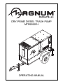
1
DRY-PRIME DIESEL TRASH PUMP MTP6500FH ww w m -p -ll c co m OPERATING MANUAL INTRODUCTION This manual provides information and procedures to safely operate and maintain the engine and pump. For your own safety and protection from physical injury, carefully read, understand, and observe the safety instructions described in this manual. The information contained in this manual was based on machines in production at the time of publication. Magnum Products LLC reserves the right to change any portion of this information without notice. DO NOT MODIFY or use this equipment for any application other than which it was designed for. Magnum Products LLC recommends that a trained and licensed professional perform all electrical wiring and testing functions. Any wiring should be in compliance with the United States National Electric Code (NEC), state and local codes and Occupational Safety and Health Association (OSHA) guidelines. Keep a copy of this manual with the unit at all times. Additional copies are available from Magnum Products LLC, or can be found at www.m-p-llc.com. An Engine Operators Manual was also supplied with the unit at the time of shipment from the factory. The manual provides detailed operation and maintenance procedures for the engine. Additional copies of the engine operators manual are available from the engine manufacturer. MAGNUM PRODUCTS LLC 215 Power Drive • Berlin, WI 54923 U.S.A. Phone: 920-361-4442 FAX: 920-361-4416 Toll Free: 1-800-926-9768 www.m-p-llc.com For technical or parts QUESTIONS, please contact Magnum Products’ Customer Support or Technical Support team at 920-361-4442. Please have your serial number available. To ORDER SERVICE PARTS, please contact the dealer from which you purchased the unit, or call Magnum Products to locate a dealer in your area. Engine Make:__________________________________________ Engine Serial Number:___________________________________ Engine Model Number: __________________________________ Pump Make:___________________________________________ Pump Model Number: ___________________________________ Pump Serial Number: ___________________________________ Unit Model Number:_____________________________________ Unit Serial Number: _____________________________________ WARNING CALIFORNIA PROPOSITION 65 WARNING: Diesel engine exhaust and some of its constituents are known to the state of California to cause cancer, birth defects and other reproductive harm. 2 TABLE OF CONTENTS Page INTRODUCTION ............................................................................................................................... 2 TABLE OF CONTENTS ..................................................................................................................... 3 SAFETY NOTES ............................................................................................................................... 4 OPERATING SAFETY ....................................................................................................................... 4 ENGINE SAFETY .............................................................................................................................. 5 SERVICE SAFETY ....................................................................................................................... 5 - 6 TOWING SAFETY ............................................................................................................................. 6 REPORTING TRAILER SAFETY DEFECTS .................................................................................... 6 SAFETY SYMBOL SUMMARY ......................................................................................................... 7 UNIT SERIAL NUMBER LOCATIONS .............................................................................................. 7 LOCATIONS & CONTROLS ......................................................................................................... 8 - 9 SPECIFICATIONS ........................................................................................................................... 10 FRONT HOOD OPERATION .......................................................................................................... 11 REAR HOOD OPERATION ...................................................................................................... 12 - 13 MAIN CONTROL PANEL COMPONENTS ..................................................................................... 14 CONTROL PANEL LEDS ................................................................................................................ 15 PRE-USE CHECKPOINTS .............................................................................................................. 16 PUMP SET UP ................................................................................................................................ 16 STARTING THE PUMP ............................................................................................................ 17 - 18 SUCTION SPECIFICATIONS .......................................................................................................... 18 STOPPING THE PUMP .................................................................................................................. 19 AUTOMATIC SHUTDOWN .............................................................................................................. 19 REMOTE/AUTO STARTING ........................................................................................................... 19 ENGINE AND PUMP MAINTENANCE ........................................................................................... 19 ENGINE BREAK-IN REQUIREMENTS ........................................................................................... 19 PUMP BEARING FRAME LUBRICATION ...................................................................................... 20 MECHANICAL SEAL LUBRICATION .............................................................................................. 20 DAILY WALK AROUND INSPECTION ............................................................................................ 21 BELT TENSION ............................................................................................................................... 21 MAINTENANCE SCHEDULE ................................................................................................... 21 - 22 TOWING THE TRAILER ................................................................................................................. 22 TRAILER WHEEL BEARINGS ........................................................................................................ 22 LIFTING THE PUMP ....................................................................................................................... 23 PUMP TROUBLESHOOTING ......................................................................................................... 24 ENGINE FAULT SHUTDOWN TROUBLESHOOTING ................................................................... 25 TRAILER LIGHTS WIRING DIAGRAM ............................................................................................ 26 DC WIRING DIAGRAM ................................................................................................................... 27 3 SAFETY NOTES This is the safety alert symbol. It is used to alert you to potential personal injury hazards. Obey all safety messages that follow this symbol to avoid possible injury or death. This manual contains DANGERS, WARNINGS, CAUTIONS, NOTICES and NOTES which must be followed to prevent the possibility of improper service, damage to the equipment, personal injury or death. The following formatting options will apply when calling the readers attention to the DANGERS, WARNINGS, CAUTIONS, NOTICES and NOTES. DANGER INDICATES A HAZARDOUS SITUATION WHICH, IF NOT AVOIDED, WILL RESULT IN DEATH OR SERIOUS INJURY. WARNING Indicates a hazardous situation which, if not avoided, could result in death or serious injury. CAUTION Indicates a hazardous situation which, if not avoided, may result in minor or moderate injury. Indicates a hazardous situation which, if not avoided, may result in property or equipment damage. Note: Notes contain additional information important to a procedure and will be found within the regular text body of this manual. OPERATING SAFETY Before using the pump be sure you read and understand all of the instructions! This equipment was designed for specific applications; DO NOT modify or use this equipment for any application other than which it was designed for. Equipment operated improperly or by untrained personnel can be dangerous! Read the operating instructions and familiarize yourself with the location and proper use of all instruments and controls. Inexperienced operators should receive instruction from someone familiar with the equipment before being allowed to operate or set up the pump. The following points should be practiced at all times: 4 • The area immediately surrounding the pump should be dry, clean, and free of debris. • Position and operate pump on a firm, level surface. • NEVER start a unit in need of repair. • NEVER modify the pump or use it in a manner other than for what it was designed. • Do not start the pump if any panels or guards are loose or missing. • Move the engine start switch to the “OFF” position when servicing or troubleshooting. • Use hearing protection if you will be near an operating pump for an extended period of time. • Keep clear of pump suction and discharge openings while pump engine is running. ENGINE SAFETY Internal combustion engines present special hazards during operation and fueling! Failure to follow the safety guidelines described below could result in severe injury or death. Also read and follow all safety warnings described in the Engine Operators Manual. A copy of this manual was supplied with unit when it was shipped from the factory. • DO NOT run engine indoors or in an area with poor ventilation unless exhaust hoses are used. Diesel engine exhaust contains carbon monoxide, a deadly, odorless and colorless gas which, if inhaled, can cause nausea, fainting or death. Make sure engine exhaust cannot seep into closed rooms or ventilation equipment. • DO NOT fill fuel tank near an open flame, while smoking, or while engine is running. DO NOT fill tank in an enclosed area with poor ventilation. • DO NOT operate with the fuel tank cap loose or missing. • DO NOT operate on a combustible surface. • DO NOT touch or lean against hot exhaust pipes or engine block. • DO NOT clean air filter with gasoline or other types of low flash point solvents. • DO NOT remove engine coolant cap while engine is hot. • DO NOT operate the unit without a functional exhaust system. Prolonged exposure to sound levels in excess of 85 DBA can cause permanent hearing loss. Wear hearing protection when working around a running engine. • Keep hands, feet and loose clothing away from moving parts on the pump and engine. • Keep area around exhaust pipes and radiator free of debris to reduce the chance of an accidental fire. • Batteries contain sulfuric acid which can cause severe injury or death. Sulfuric acid can cause eye damage, burn flesh or eat holes in clothing. Protective eye wear and clothing are necessary when working on or around the battery. Always disconnect the NEGATIVE (-) battery cable from the corresponding terminal before performing any service on the engine or other components. • Shut down the engine if any of the following conditions exist during operation: 1. Noticeable change in engine speed. 2. Loss of pumping output. 3. Sparking occurs. 4. Engine misfires or there is excessive engine/pump vibration or noise. SERVICE SAFETY Only a qualified electrician should troubleshoot or repair electrical problems occurring in this equipment. • Before servicing the trash pump, make sure the engine start switch is turned to OFF and the negative terminal on the battery is disconnected. NEVER perform even routine service (oil/filter changes, cleaning, etc.) unless all electrical components are shut down. • NEVER service electrical components if clothing or skin is wet. If the unit is stored outside, check the engine for any moisture and dry the unit before use. • NEVER open the radiator cap or oil drain plug while the engine is running or before the engine has cooled down. Pressurized coolant and hot engine oil can cause severe burns. Allow the engine to cool completely before attempting any service work. • NEVER attempt to modify the engine, pump or related components. • NEVER wash the unit with a power washer or high pressure hose. • Keep hands, feet, hair and loose clothing away from moving parts. • Replace all guards and safety devices immediately after servicing. 5 • Replace all missing and hard-to-read labels. Labels provide important operating instructions and warn of dangers and hazards. • Make sure slings, chains, hooks, ramps, jacks, and other types of lifting devices are attached securely and have enough weight-bearing capacity to lift or hold the equipment safely. Always remain aware of the position of other people around you when lifting the equipment. TOWING SAFETY Towing a trailer requires care! Both the trailer and vehicle must be in good condition and securely fastened to each other to reduce the possibility of an accident. Also, some states require that large trailers be registered and licensed. Contact your local Department of Transportation office to check on license requirements for your particular unit. • Check that the hitch and coupling on the towing vehicle are rated equal to, or greater than, the trailer's “gross vehicle weight rating” (GVWR). • Check tires on trailer for tread wear, inflation, and condition. • Inspect the hitch and coupling for wear or damage. DO NOT tow trailer using defective parts! • Make sure the trailer hitch and the coupling are compatible. Make sure the coupling is securely fastened to the vehicle. • Connect safety chains in a crossing pattern under the tongue and attach the breakaway cable TO THE REAR BUMPER OF THE TOWING VEHICLE. Do not attach the cable to the trailer hitch. • Make sure directional and brake lights on the trailer are connected and working properly. • Check that all lug nuts holding wheels on are tight and that none are missing. • Maximum recommended speed for highway towing is 45 m.p.h. Recommended off-road towing speed is not to exceed 10 m.p.h. or less depending on terrain. The trailer is equipped with hydraulic surge brakes or electric surge brakes. Check the operation of the brakes by braking the vehicle at a slow speed before entering traffic. Both the trailer and the vehicle should brake smoothly. If the trailer seems to be pushing, check the level in the surge brake fluid reservoir. When towing, maintain extra space between vehicles and avoid soft shoulders, curbs and sudden lane changes. If you have not pulled a trailer before, practice turning, stopping, and backing up in an area away from heavy traffic. A film of grease on the coupler will extend coupler life and eliminate squeaking. Wipe the coupler clean and apply fresh grease each time the trailer is towed. REPORTING TRAILER SAFETY DEFECTS If you believe your trailer has a defect which could cause a crash or could cause injury or death, you should immediately inform the National Highway Traffic Safety Administration (NHTSA) in addition to notifying Magnum Products LLC. If NHTSA receives similar complaints, it may open an investigation; and if it finds that a safety defect exists in a group of vehicles, it may order a recall and remedy campaign. However, NHTSA cannot become involved in individual problem between you, your dealer, or Magnum Products LLC. To contact NHTSA, you may either call the Auto Safety Hotline toll-free at 1-888-327-4236 (TTY:1-800-424-9153), go to http://www.safercar.gov; or write to: Administrator NHTSA 1200 New Jersey Avenue S.E. Washington, DC 20590 You can also obtain other information about motor vehicle safety from http://www.safercar.gov. 6 SAFETY SYMBOL SUMMARY This equipment has been supplied with numerous safety and operating decals. These decals provide important operating instructions and warn of dangers and hazards. Replace any missing or hard-to-read decals and use care when washing or cleaning the unit. Decal placement and part numbers can be found in the parts manual. Below is a summary of the intended meanings for the symbols used on the decals. Safety alert symbol; Used to alert you to potential personal injury hazards. Asphyxiation hazard; Operate in well ventilated area. Hot surface(s) nearby. Hazardous voltage. Disconnect battery before servicing. Belt/entanglement hazard; Keep body parts clear of this area. Anchor/tie down point. Rotating fan hazard; do not operate without guards in place. Keep body parts clear of this area. Burn/scald hazard; pressurized steam. Rotating impeller blade hazard; Keep body parts clear of this area. Use clean diesel fuel only. Moving parts can crush and cut; Keep body parts clear of this area. Remove negative battery cable before performing any service on unit. Stop engine before fueling. Read and understand the supplied operating manual before operating unit. Hearing protection required while operating unit. Lift here only. Fire/explosion hazard; Keep open flames away from unit. Crush/pinch hazard; Keep body parts clear of this area. UNIT SERIAL NUMBER LOCATIONS Unit ID Tag V.I.N. Tag MANUFACTURED BY/FABRIQUE PAR: MAGNUM PRODUCTS LLC GVWR/PNBV: GAWR/PNBE Refer to the locations illustrated to find the unit ID tag, and trailer ID tag on your unit. Important information, such as the unit serial number, model number and Vehicle Identification Number (V.I.N.) for your trailer are found on these tags. Record the information from these tags, so it is available if the tags are lost or damaged. When ordering parts or requesting technical service assistance, you will be asked to specify this information. MODEL MTP6500FH/STD SERIAL NUMBER 000000 kg lbs MADE IN USA 0000 0000 TIRE/PNEU RIM/JANTE THIS VEHICLE CONFORMS TO ALL APPLICABLE STANDARDS PRESCRIBED UNDER THE CANADIAN MOTOR VEHICLE SAFETY REGULATIONS IN EFFECT ON THE DATE OF MANUFACTURE. / CE VEHICULE EST CONFORME A TOUTES LES NORMES QUI LUI SONT APPLICABLES EN VERTU DU REGLEMENT SUR LA SECURITE DES VEHICULES AUTOMOBILES DU CANADA EN VIGUEUR A LA DATE SA FABRICATION. V.I.N./N.I.V.: 00000000000000000 DATE: 00/0000 COLD INFL. PRESS./PRESS. DE GONF A FROID SGL/DUAL KPA(PSI/LPC) TYPE/TYPE DE VEHICULE: THIS VEHICLE CONFORMS TO ALL APPLICABLE U.S. FEDERAL MOTOR VEHICLE SAFETY STANDARDS (FMVSS) IN EFFECT ON THE DATE OF MANUFACTURE SHOWN ABOVE. TRAILER MTG Trailer ID Tag MAGNUM PRODUCTS LLC BERLIN, WI 54923 USA (800) 926-9768 MODEL MTG55F/STD SERIAL NUMBER 000000 kg lbs MADE IN USA 000 000 7 LOCATIONS & CONTROLS 8 9 7 10 11 6 12 5 4 3 13 2 14 1 15 16 17 18 25 24 23 22 19 21 8 20 1. ENGINE STARTING BATTERY 2. PUMP OUTLET (DISCHARGE) PORT. Opening for discharge of liquids from the pump. Fittings can be threaded or bolted to the pump flange. 3. REAR LEVELING JACKS. Used to level the rear of the pump on rough or uneven ground. 4. CHECK VALVE. A valve that permits flow in one direction only. (Required for pump priming.) 5. DRAIN/SUCTION HOSE RELEASE VALVE. (Located on rear skid.) Allows for complete draining of the pump volute for storage and/or maintenance. This valve can also be opened to relieve pressure on the rear suction hose to facilitate removal of the hose. 6. PUMP INLET (SUCTION) PORT. Opening for intake of liquids into the pump. Fittings can be threaded or bolted to the pump flange. 7. REAR HOOD PRIMARY LATCH. See page 12 for hood operating information. 8. FLOODED SUCTION BYPASS VALVE. This valve is used to prevent water from back flowing into the compressor when there is a flooded suction. The valve should remain open for normal pump operation. (Pictured in open position.) 9. PUMP VOLUTE (HOUSING). Cast-iron housing for pump mechanical components. 10. ANTI-SHUT LATCH. See page 12 for hood operating information. 11. CENTRAL LIFT EYE. Used for lifting the pump. 12. FRONT HOOD. See page 11 for hood operating information. 13. FRONT HOOD LATCH. See page 11 for hood operating information. 14. FRONT LEVELING JACK. Used to level the pump on rough or uneven ground and to aid in attaching the pump to a tow vehicle. 15. ENGINE COOLANT DRAIN 16. ENGINE OIL FILL 17. AIR CLEANER ASSEMBLY 18. REAR HOOD. See page 12 for hood operating information. 19. REAR HOOD SECONDARY LATCH. See page 12 for hood operating information. 20. CONTROL PANEL. Controls and indicators for pump operation. 21. MANUAL HOLDER. Storage for operator manuals. 22. ENGINE OIL DRAIN 23. FUEL FILL PORT. Lockable port for filling the fuel tank with clean DIESEL fuel. 24. HAND THROTTLE. Controls pump engine speed. 25. COOLANT OVERFLOW BOTTLE Note: Use hoses and fittings that are specifically designed and sized for this type of equipment. 9 SPECIFICATIONS Read this manual carefully before attempting to use this pump. The potential for property damage, personal injury or death exists if this equipment is misused or installed incorrectly. Read all of the manuals included with this unit. Each manual details specific information regarding items such as set up, use and service requirements. MAGNUM MODEL MTP6500FH Engine Make/Brand......................................................................................... John Deere Model .................................................................................................. PE5030TF270 Type .................................................................................................... Diesel, liquid cooled, 4-stroke Displacement in3 (L) .......................................................................... 186 (3.1) Cylinders - qty ..................................................................................... 5 Engine Rated Speed rpm .................................................................. 2800 Engine Power @ Rated Speed - Intermittent hp (kW) ....................... 75.0 (56.2) Engine Power @ Rated Speed - Continuous hp (kW) ....................... 64.0 (47.8) Engine Operating Speed rpm ............................................................ 2000 Engine Power @ Operating Speed - Intermittent hp (kW) ................. 67.0 (49.8) Engine Power @ Operating Speed - Continuous hp (kW) ................ 57.0 (44.4) Fuel Consumption - 100% load gph (Lph) ........................................ 2.8 (10.6) Battery Type - Group Number............................................................. 24 Battery Voltage (Quantity per Unit) ..................................................... 12V (1) Battery Rating ..................................................................................... 720 CCA Alternator Rating ................................................................................. 70A Pump Make/Brand......................................................................................... Pioneer Pump Inc. Model .................................................................................................. VP66S10L72-EG410 Fitting Size .......................................................................................... 6" NPTF Impeller Material ................................................................................. Ductile Iron Impeller Diameter in (mm) ................................................................. 10 (254) Shaft Material ...................................................................................... Lasalle stressproof (modified AISI 1144 STL) Volute Material .................................................................................... ASTM A536 Ductile Iron Wear Plate Material............................................................................. ASTM A536 Ductile Iron Pump Set (Engine/Pump) Maximum Diameter of Solids in (mm) ............................................... 3.0 (76.2) Maximum Pump Output gpm (Lpm) .................................................. 3050 (11546) Maximum Lift Suction ft (m) ............................................................... 28 (8.5) Maximum Operating Speed rpm ........................................................ 2200 Total Dynamic Head ft (m) ................................................................. 165 (50) Sound dB(A) 23 ft @ prime .............................................................. 70 Dimensions (L x W x H) Skid Mounted in (m) .......................................................................... 95 x 35 x 55 (2.41 x 0.89 x 1.40) Trailer Mounted in (m) ....................................................................... 150 x 57 x 74 (3.81 x 1.45 x 1.88) Weights Dry Weight, Skid Mounted lbs (kg) .................................................... 2733 (1240) Operating Weight, Skid Mounted lbs (kg) ......................................... 3525 (1599) Dry Weight, Trailer Mounted lbs (kg) ................................................ 3283 (1489) Operating Weight, Trailer Mounted lbs (kg) ...................................... 4075 (1848) Capacities Fuel Tank Volume gal (L) ................................................................... 110 (416) Usable Fuel Volume gal (L) ............................................................... 95 (360) Maximum Run Time hrs .................................................................... 34 Trailer Number of Axles ................................................................................. 1 Capacity - Axle Rating lbs (kg) .......................................................... 5000 (2268) Tire Size in ......................................................................................... 15 Brakes................................................................................................. Surge Hitch - Standard .................................................................................. 2" Ball Maximum Tire Pressure psi ............................................................... 65 SPECIFICATIONS ARE SUBJECT TO CHANGE WITHOUT NOTICE. 10 FRONT HOOD OPERATION WARNING Stay clear of hood and lift structure when opening and closing pump hoods. Personal injury may result. TO OPEN THE FRONT HOOD: 1. With your right hand, grip the handle located on the upper right side of the front panel. 2. With your left hand, pull the hood latch located on the upper corner of the left hood side (see Figure A). Tilt the hood open until it contacts the bulkhead panel. CAUTION Pump hoods are heavy. Use caution when opening or closing. TO CLOSE THE FRONT HOOD: 1. Make sure skid is free of debris and all personnel are clear of unit. CAUTION Do not attempt to close the hood from the sides of the unit. Proceed to the front of the unit to close the hood. Failure to close the hood correctly could result in personal injury and equipment damage. 2. While standing at the front of the unit, slowly push the hood forward and allow it to close firmly to ensure the hood latch is engaged. 3. Verify the hood is securely closed by attempting to open without pulling the hood latch. 11 REAR HOOD OPERATION WARNING Stay clear of hood and lift structure when opening and closing pump hoods. Personal injury may result. TO OPEN THE REAR HOOD: 1. Open front hood. 2. Verify that the control door is completely closed and secure. 3. Pull lever located under lift structure to release the primary hood latch (see Figure A). 4. Proceed to rear of unit to release the secondary hood latch and tilt the hood open (see Figure B). A. With your right hand, grip the handle located on the rear of the hood. B. With your left hand, pull the hood latch located on the upper corner of the left hood side (see Figure C). Tilt the hood completely open; travel is limited by two metal guide straps. CAUTION Pump hoods are heavy. Use caution when opening or closing. 5. Verify the red safety link is engaged and undamaged. This link is located on the left side metal guide strap (see Figure D). WARNING If the red safety link is not properly engaged, unintentional closing of the hood could result, causing personal injury or equipment damage. 12 REAR HOOD OPERATION WARNING Stay clear of hood and lift structure when opening and closing pump hoods. Personal injury may result. TO CLOSE THE REAR HOOD: 1. Make sure the skid is free of debris and all personnel are clear of unit. 2. Verify that the control door is completely closed and secure. 3. Release the red safety link located on the left side metal guide strap by rotating the link counterclockwise. Failure to release the safety link could result in damage to the link or other components. CAUTION Do not attempt to close the hood from the sides of the unit. Proceed to the rear of the unit to close the hood. Failure to close the hood correctly could result in personal injury and equipment damage. 4. While standing at the rear of the unit, slowly push the hood forward and allow it to close firmly to ensure the hood latches have engaged. 5. Verify the hood is securely closed by attempting to open without releasing the hood latches. 13 MAIN CONTROL PANEL COMPONENTS 1 12 2 11 3 10 4 VACUUM 9 5 8 6 7 1. DC VOLTAGE GAUGE. Displays DC voltage of the engine starting battery. Typical range is 12-14 volts. 2. FUEL LEVEL GAUGE. Displays the amount of fuel remaining in the fuel tank. 3. ENGINE COOLANT TEMPERATURE GAUGE. Displays engine coolant temperature. Typical range is 180-210° F. 4. ENGINE OIL PRESSURE GAUGE. Displays engine oil pressure. Typical range is 30-80 psi. 5. VACUUM GAUGE. Used to determine if the pump is achieving prime. After shutdown, this gauge is used to determine if the pump is holding prime. Typical range is 20-25 in/Hg. 6. CONNECTIONS FOR OPTIONAL FLOAT SWITCHES. 7. EMERGENCY STOP SWITCH. Used to stop engine in case of emergency by interrupting power to the fuel solenoid. 8. FUEL TRANSFER PUMP SWITCH. Switch for optional fuel transfer pump for extended pump operation. 9. EMERGENCY STOP ACTIVATED LIGHT. Notifies operator that the emergency stop is activated. 10. ENGINE START SWITCH. Used to start and stop the pump engine or to allow for remote starting of the pump by a dry-contact closure type of switch. 11. CONTROL PANEL LEDS. Indicates various engine operating parameters and faults. These LEDs either flash or are steady state. See page 15 for more information. 12. ENGINE TACHOMETER/HOUR METER. Displays engine speed in revolutions per minute (rpm) and keeps track of engine hours for service. 14 CONTROL PANEL LEDS FLASHING LOW FUEL / LOW COOLANT STEADY LOW OIL PRESSURE HIGH TEMPERATURE OVERCRANK NO SPEED SIGNAL ENGINE REST OVERSPEED ENGINE RUNNING PREHEAT FLASHING LEDS • • • LOW FUEL / LOW COOLANT: Indicates a low fuel level or low coolant level shutdown (optional). NO SPEED SIGNAL: Indicates a pump engine shut down due to a loss of signal from the engine’s magnetic pickup. Refer to the TROUBLESHOOTING section for possible causes. ENGINE REST: Indicates the engine has paused between starting attempts. STEADY STATE LEDS • • • • • • LOW OIL PRESSURE: Indicates a pump engine shut down due to low engine oil pressure. Refer to the TROUBLESHOOTING section for possible causes. HIGH TEMPERATURE: Indicates a pump engine shut down due to the coolant temperature exceeding 235° F. Refer to the TROUBLESHOOTING section for possible causes. OVERCRANK: Indicates the pump engine failed to start after three attempts. Refer to the TROUBLESHOOTING section for possible causes. OVERSPEED: Indicates shutdown due to the pump engine running too fast. Refer to the TROUBLESHOOTING section for possible causes. ENGINE RUNNING: Indicates proper operation of the pump engine. PREHEAT: Indicates operation of the engine’s glow plugs during the engine starting procedure. 15 PRE-USE CHECKPOINTS Before using the pump, be sure to check the following: • • • • Place the pump as close as possible to the liquid being pumped, keeping the number of hose sections and couplings to a minimum. The pump should be the highest point between the intake and outlet section of the hoses. Make sure the ground is firm and as level as possible. Check the pump discharge area; make sure it will not erode the material under the pump or damage any nearby structures. Make sure all hose couplings are of the same size and type. WARNING The pump is designed to handle water and/or other liquids containing some slurries and other entrapped solids up to 3.0 inches (7.6 cm) in diameter. It MUST NOT be used to pump volatile, corrosive or flammable materials that may damage the pump, cause pump failure or result in explosion! PUMP SET UP 1. Disconnect the pump from the tow vehicle by turning the tongue jack clockwise to raise the tongue from the hitch. Disconnect all safety chains, surge brake cables and the trailer wiring harness. 2. Lower rear leveling jacks from the travel position. Turn the jack handles clockwise until the leveling feet are in firm contact with the ground. Adjust the front and rear jacks until the pump is as level as possible. 3. If necessary, open the rear hood and attach fittings to both the intake and outlet openings of the pump, making sure they match the fittings on the hoses. Make sure a gasket/seal is in place between the pump volute and the flange on the fitting being attached. Tighten all hardware completely to ensure an airtight seal. Threaded fittings require the use of pipe thread sealant/lubricant. SE AL SE AL 4. Attach a rigid fill hose or pipe to the intake (suction) side of the pump. Make sure the seals are present in the fitting on the pump before attaching fittings. Note: Lubricate the seals to ensure an airtight seal. 5. Attach a rigid intake screen or strainer to the end of the fill hose before placing it in the liquid. This will prevent large items or excessive trash from entering the pump housing. The screen must have enough openings to equal 4 times the area of the intake hose (6” x 3.14 = 18.84 sq. in x 4 = 75.36 sq. in.). 6. Attach a flexible hose to the outlet (discharge) side of the pump. Make sure the o-ring seal is present in the fitting on the pump before attaching the fitting. Note: Lubricate the seal to ensure an airtight seal. 7. Check the intake and outlet hoses for sharp bends or kinks that may restrict pump flow before proceeding. The intake hose should slope upwards toward the pump to avoid development of air pockets in the hose which may lead to pump cavitation. Keep the hoses as straight as possible. The pump is now ready for use. 16 STARTING THE PUMP Before starting the pump, be sure to check the following: • • • • Make sure all hose couplings, covers and plugs are tight. Check the oil level in the mechanical seal oil reservoir bottle. Do not allow the bottle to run dry. Check the engine oil level, coolant level and fuel level. Make sure the engine starting battery is connected. 1. Make sure the Emergency Stop switch is pulled out (deactivated). 2. Push the Engine Start Switch up to the MANUAL START position. The PREHEAT LED on the control panel will light up to indicate activation of the engine glow plugs. Once sufficient time has passed, the engine should crank, start and run, slowly building up speed. 3. Allow the engine to run until it reaches a constant speed. Once it is running smoothly, the engine speed can be adjusted by the throttle, located above the fuel fill port. To adjust the engine speed: A. Loosen the locking ring on the throttle, located next to the mounting bracket, by turning counterclockwise. B. Push and hold the center button on the throttle: ○ PULL the throttle out to INCREASE engine speed. ○ PUSH the throttle in to DECREASE engine speed. C. Fine engine speed adjustment can be made by turning the throttle clockwise or counterclockwise. D. Once the desired engine speed has been attained, lock the throttle by turning the locking ring clockwise. PU SH PU LL 4. The pump should prime and begin to discharge liquid within minutes. A high suction lift or low engine speed will require a longer time to prime and pump. 5. Use the engine throttle to adjust the pump flow. Several factors can influence pump output: • The temperature, viscosity amount of entrapped solids in the liquid being moved. • The length, diameter and number of bends of the intake and outlet hoses. • The total suction height (lift) of the pump. • The altitude above sea level where the pump is operating. WARNING Never adjust the pump flow by attaching a valve to the intake or outlet side of the pump. Restricting the flow in this way can cause the pump to overheat, creating extreme pressure inside the pump volute. Explosion of the pump volute and serious personal injury may result! 6. As the pump operates, avoid running the intake side of the pump dry. Air from the intake side of the pump may cause cavitation, causing damage to the pump impeller. The intake hose must be kept 4-5 times the hose diameter (4-5 x 6” = 24-30”) below the surface of the liquid being pumped. 17 7. Use the table below for approximate flow rates for the 6” pump. 6 Inch SUCTION SPECIFICATIONS B C A A = Suction Lift: The distance between the centerline of the pump impeller and the surface of the liquid being pumped. B = Vertical Discharge Head: Vertical distance from the centerline of the pump inlet to the centerline of the highest point of discharge. C = Total Dynamic Head (TDH): Suction lift plus vertical discharge plus friction loss. Note: To calculate PSI, divide TDH in feet by 2.31. Example: TDH (35 ft.) = 15.15 PSI 2.31 18 STOPPING THE PUMP 1. Reduce the engine speed by adjusting the engine throttle. 2. Allow the engine to idle briefly before switching the engine start switch to the center (OFF) position. Do not use the Emergency Stop switch unless absolutely necessary. Stopping the pump suddenly may cause shock waves to be transmitted back to the pump volute, causing pump damage. To activate the emergency stop, push the stop switch in. To deactivate the switch, pull the switch out. 3. The pump is adequately prepared for outside storage. See the pump Operation and Maintenance Manual for additional suggestions for long-term storage. In freezing temperatures, drain the pump volute case of pumpage when the unit is idle to avoid freezing and possible equipment damage. AUTOMATIC SHUTDOWN The pump is equipped with a low oil pressure and a high temperature automatic shutdown system. This system will automatically shut off the fuel supply to stop the engine if oil pressure drops too low or the engine exceeds normal operating temperature. Return the engine start switch to the “OFF” position to reset the controller; restart the pump engine after you have determined the cause of the shutdown. Refer to the ENGINE FAULT SHUTDOWN TROUBLESHOOTING section for more information. REMOTE/AUTO STARTING The pump can be configured to start automatically by the addition of dry-contact closure float level switches. These connections are found on the control panel next to the emergency stop button. Both float switches must be connected for automatic starting to occur. Contact Magnum Products’ Technical Service Department at 1-800-926-9768 or 1920-361-4442 for more information. ENGINE AND PUMP MAINTENANCE Poorly maintained equipment can become a safety hazard! In order for the equipment to operate safely and properly over a long period of time, periodic maintenance and occasional repairs are necessary. NEVER perform even routine service (oil/filter changes, cleaning, etc.) unless the engine start switch is turned to off “O” and the negative (-) cable on battery is disconnected. Attach a “DO NOT START” sign to the control panel. This will notify everyone that the unit is being serviced and will reduce the chance of someone inadvertently trying to start the unit. Never wash the unit with a high pressure hose or with any kind of power washer. Never wash the engine block or fuel tank with a power washer or steam cleaner. Water may collect in the pump control panel or other electrical parts, causing damage. ENGINE BREAK-IN REQUIREMENTS Note: During the first 20 hours of operation, avoid long periods of low engine speed or sustained maximum engine speed. The engine is supplied with engine break-in oil from the factory. Extra care during the first 100 hours of engine operation will result in better performance and longer engine life. Note: DO NOT exceed 100 hours of operation with the break-in oil. Operate the engine at high engine speeds (60-90% of maximum) as much as possible. If the engine has spent significant time at idle, constant speeds and/or light load or if makeup oil is required, a longer breakin period may be needed. Consult the engine OPERATION AND MAINTENANCE MANUAL for a full description of necessary procedures on the addition of break-in oil and extension of the break-in period. 19 PUMP BEARING FRAME LUBRICATION The lubrication of the ball bearings depends on speed, load, ambient temperature, contamination, moisture, intermittent or continuous service and other factors. These re-greasing recommendations are general and are to be used with good judgement and consideration of the pump service. The following table contains suggested lubrication intervals: 2200 RPM 1800 RPM 1200 RPM 2,500 Hours 3,500 Hours 5,000 Hours To lubricate the ball bearings, remove the plastic covers from the zerk fittings. Ensure that the zerk fitting and the end of the grease gun are clean. Use only a hand-operated grease gun with ball bearing grease. Use one of the following, or equivalent; Texaco Starplex Moly 2, Mobile MobiLux No. EP2, Shell Alvania EP2, Chevron SRI. MECHANICAL SEAL LUBRICATION The mechanical seal oil reservoir supplies lubrication and cooling to the outboard side of the mechanical seal without any liquid in the pump. Monitor the oil level in the oil fill bottle, add oil as needed. During normal operation the oil should be changed every three months, or more frequently if contamination or discoloration is detected. The external oil reservoir (bottle) is filled via a plug on the top of the bottle. There is a petcock located on the opposite side of the run-dry gland from the oil inlet line. During initial filling, this petcock should be opened to allow the air to vent from the gland. Use turbine oil with an ISO rating of 32 or lower. If you have unusual pumping conditions contact Pioneer Pump, Inc. Oil used in the reservoir (bottle) should be ISO VG 32 Turbine Oil or Automatic transmission oil, equivalent to one of the following manufacturer’s products: Chevron Turbine oil GST 32, Mobile DTE 797, Shell Turbo T oil 32. MECHANICAL SEAL OIL RESERVOIR BALL BEARING GREASE ZERK 20 DAILY WALK AROUND INSPECTION Look for conditions that could hinder performance or safety, such as (but not limited to) oil/coolant/fuel leakage, blocked vents, loose/missing hardware and electrical connections Visually inspect the fan belt for cracks, fraying, stretching and that the belt is properly seated in pulley grooves. Replace the belt according to the manufacturer’s recommendations. Note: At the 500 hour/12 month service interval, it is recommended that the belt be removed and checked for wear. While the belt is removed, inspect pulleys and bearings. Rotate and feel for hard turning or unusual sounds. If pulleys or bearings need replacement contact John Deere. Note: Failure to perform a daily inspection may result in serious damage to the prime mover. BELT TENSION John Deere engines use two types of belt tensioners: manual and automatic. Adjust the belt using the manual tensioner according to the manufacturer’s specifications. The automatic tensioner cannot be adjusted or repaired and is designed to maintain proper tension over the belt’s life. Units with the automatic belt tensioner must be inspected according to the manufacturer’s specifications. MAINTENANCE SCHEDULE The periodic maintenance schedule below lists basic maintenance intervals for the pump and engine. For detailed maintenance procedures refer to the Engine Operator’s Manual and the Pump Operation & Maintenance Manual. Copies of these manuals were supplied with the unit when it was shipped from the factory. For additional or replacement copies of these manuals, contact an authorized dealer in your area. Maintenance Action Daily Check Engine Oil Level Check Engine Coolant Level Check Fuel Level Check Mechanical Seal Oil Level * Check for Fuel Leaks Check for Coolant Leaks Check Fan Belt Tension Check Tire Inflation Check Flange Fitting Hardware 100 Hours Check Fan Belt Condition Clean Fuel Filter Check Condition of Wear Plate 250 Hours Change Mechanical Seal Oil * Change Engine Oil and Filter ** Check Condition of Volute Seals Check Exhaust System Components Replace Fuel Filter Element Clean Air Filter Element, Replace if Necessary 500 Hours 2000 Hours 2500 Hours 21 Maintenance Action Daily 100 Hours 250 Hours 500 Hours Service Battery Flush Cooling System Clean Crankcase Vent Tube Check Compressor Mounting Hardware Replace Fan Belt 2000 Hours Replace Cooling System Hoses Pressure Test Cooling System Check Engine Valve Clearance Check Flex Coupling Condition Check Pump to Engine Hardware 2500 Hours Lubricate Pump Bearings *** * See “MECHANICAL SEAL LUBRICATION” on page 20 for details. ** Change the engine oil and oil filter after the initial 100 hours of operation, then every 250 hours thereafter. *** See table on page 20 for bearing lubrication details. TOWING THE TRAILER 1. Use the jack to raise or lower the trailer onto the hitch of the towing vehicle. Lock the hitch coupling and attach the safety chains or cables to the vehicle. Release the jack locking pin and rotate the jack into the travel position. Make sure the locking pin snaps into place. 2. Connect any trailer wiring to the tow vehicle. Check for proper operation of the stop and signal lights. 3. Check for proper inflation of the trailer tires. 4. Check the wheel lugs. Tighten or replace any that are loose or missing. If a tire has been removed for axle service or replacement, tighten the lugs in the order shown to the following specifications: A. Start all lug nuts by hand. B. First pass tighten to 20-25 Ft-Lbs (27-33 Nm). C. Second pass tighten to 50-60 Ft-Lbs (67-81 Nm). D. Third pass tighten to 90-120 Ft-Lbs (122-162 Nm). 1 3 6 4 5 2 After the first road use, retorque the lug nuts in sequence. 5. Maximum recommended speed for highway towing is 45 mph. Recommended off-road towing speed is not to exceed 10 mph or less depending on terrain. TRAILER WHEEL BEARINGS The trailer is equipped with a grease zerk fitting to allow lubrication of the wheel bearings without the need to disassemble the axle hub. To lubricate the axle bearings, remove the small rubber plug on the grease cap, attach a standard grease gun fitting to the grease zerk fitting and pump grease into the fitting until new grease is visible around the nozzle of the grease gun. Use only a high quality grease made specifically for lubrication of wheel bearings. Wipe any excess grease from the hub with a clean cloth and replace the rubber plug when finished. The minimum recommended lubrication is every 12 months or 12,000 miles; more frequent lubrication may be required under extremely dusty or damp operating conditions. 22 LIFTING THE PUMP Only lift the pump with equipment that is in good condition and that is rated to support the weight of the pump. See the specifications on page 10 for approximate weights. A central lifting eye is located on the top of the pump. The eye is connected to a central lifting frame. Attach a sling or hook directly to the lifting eye. Always remain aware of others around you when moving or lifting the pump. Suction and discharge hoses and piping must be removed from the pump before lifting. CENTRAL LIFT EYE ww w m -p -llc co m 23 PUMP TROUBLESHOOTING PUMP TROUBLESHOOTING SYMPTOM POSSIBLE CAUSE SOLUTION Pump will not prime Back pressure condition in discharge hose Drain fluid from discharge line Air leak in suction hose or fitting Tighten all connections, lubricate fitting seals Intake insufficiently submerged Lower intake hose Air leak in intake hose Air leak at pump housing Low pump output Air trapped in intake hose Relocate and/or straighten intake hose Engine speed too low Increase engine speed Intake hose collapsed Replace intake hose with a more rigid one Suction lift too high Relocate pump Excess air in liquid Allow liquid to settle Total head too high Reduce inlet and outlet hose length Impeller obstructed Remove pump suction flange and check for obstructions Worn pump components Check wear plate and impeller for wear or damage Intake insufficiently submerged Air leak in intake hose Air leak at pump housing Vibration and/or noise when pump is operating Change engine speed Intake hose collapsed Replace intake hose with a more rigid one Suction lift too high Relocate pump Excess air in liquid Allow liquid to settle Total head too high Reduce inlet and outlet hose length Impeller obstructed Remove pump suction flange and check for obstructions. Improper or low lubrication at mechanical pump seal Check wear plate and impeller for wear or damage Stop pump, inspect oil level at mechanical seal oil fill bottle Pump cavitation Reduce engine speed, lower intake hose Worn pump bearings Repair pump Impeller obstructed Remove pump suction flange and check for obstructions Worn pump components Improper or low lubrication at mechanical pump seal Worn pump bearings 24 Lower intake hose Inspect intake hoses and couplings for damage or missing components and seals Inspect gaskets, seals and o-rings at pump intake flange. Engine speed incorrect Worn pump components Pump is overheating Inspect intake hoses and couplings for damage or missing components and seals Inspect gaskets, seals and o-rings at pump intake flange, cleanout cover and priming port Check wear plate and impeller for wear or damage Stop pump, inspect oil level at mechanical seal sight glass Repair pump ENGINE FAULT SHUTDOWN TROUBLESHOOTING switch switch switch switch 25 TRAILER LIGHTS WIRING DIAGRAM 26 DC WIRING DIAGRAM GRY L BLK S REMOTE START MANUAL START FUEL PREHEAT LED OUTPUTS OVERCRANK TEMP SWITCH OVERSPEED OIL SWITCH ENGINE RUN FAILURE LED TEST BLU L S GND 19 20 WARMUP COMMON GND WATER BLK LOW OIL HIGH TEMP AUX SWITCH BLK GND REMOTE START VIO 12 AUTO MODE CRANK 1 2 3 4 11 17 18 YEL/WHT 10 16 GRY/BLK 9 BAT WHT/VIO BLK 8 14 15 RED 7 13 RED 6 RED FUEL GND 5 RED RED BAT RED #3 #2 GRD BAT BAT OIL RED - + L S GND VIO GRY N/C 85 86 L L Engine Controller S GND SPEED SIGNAL YELL BLK #1 N/O 87A SIG VIO BLU YEL - + 87 COM N/C 85 86 - + DC VOLTS 30 GRN/YEL N/O 87A COM N/C 85 86 87 GRN/YEL ORN N/O 87A COM GRY 30 RD/WHT 87 RED 30 YEL ORN RED BLK TACH BAT BLU BLK WHT/BLU RED BLK YEL STARTER SOLINOID 10 PINK ORN PINK 9 BLK 8 RED FUSE 25 AMP R 4 1 5 2 6 3 ESTOP LED RED RED 5 RED 6 7 RED C+ YEL 10 AMP RD/WHT ESTOP NC1 NC2 ESTOP 3 WHT GLOW SOLINOID RED 4 BLK RED 2 YEL NO4 WHT 1 NO3 C+ RED BLK BLK YEL BLK RD/WHT ORN GRY BLK YEL VIO WHT/BLU BLU BLK WHT/VIO BLK YEL/WHT GTB 12/B 9 11 8 10 7 6 5 4 1 3 2/B GRY/BLK BLK BLK BLK YEL ORN ALTERNATOR 13 10 7 4 1 14 11 8 5 2 15 12 9 6 3 15 12 9 6 3 14 11 8 5 2 13 10 7 4 1 GLOW PLUG MOTOR STARTER BLK WHT YEL WHT/VIO FUEL SENSOR WATER SENSOR CRANK SENSOR BLK OIL SENSOR WHT RED BLK RED B+ BATTERY 12V RED RED LOW COOLANT OIL SWITCH FUEL SOLENOID BLK TEMP SWITCH WHT/BLU VIO BLK RED RED B+ 27 REV: E PART NO: 41561 01.28.11