1
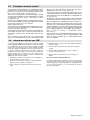
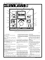
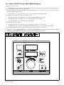
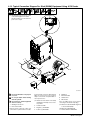
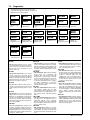
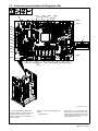
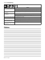
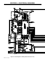
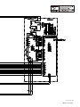
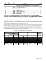
7-9. Automation Interface Module PC9 Diagnostic LEDs
1
LED11
LED13 LED25
LED28
LED12
LED14
LED27
LED31
LED30
LED1
LED2
LED3
LED4
2
LED5
LED6
LED7
LED8
LED9
LED10
LED32
LED33
LED15
LED20 LED19 LED18 LED16
LED17
LED21 LED22 LED23 LED24 LED26 LED29
216 958-A / Ref. 803 250-C
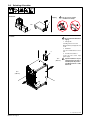
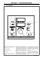
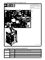
1 Automation Interface Module PC9
Diagnostic LEDs are visible inside unit,
located on PC9 mounted on left side.
Refer to Section 7-10 for information on
diagnostic LEDs.
Reinstall cover after checking diagnostic
LEDs.
2
Dip Switch S4
Dip switches are used to identify each
circuit board on the internal network. Dip
switch settings are different for each circuit
board. For proper operation, do not change
dip settings from those shown.
OM-221 771 Page 57