1
9.
Place and pin head onto center section (see Figures 13/14). Keep hands clear of center section post placement while
placing/removing head onto/off hitch base as noted on head labels. Head will tilt rearward with proper torsion spring
installation (Step 8).
10.
Add head handle with fasteners as shown in Figure 13.
11.
Slide handle grip over handle tube (using liquid soap as a lubricant will ease installation).
12.
Lubricate jaw and skid plate (If no lubrication plate is being used) with automotive type chassis grease (see Figure 14). The
jaw pin comes greased from the factory. To insure smooth jaw operation, grease should be added every 6 months to
grease fitting on top of head (see Figure 14). Refer to the Lubrication section in this manual.
Grip
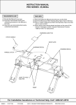
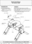
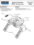
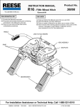
Figure 13 : Head Placement
Handle tube
3/8 Carriage bolt (2)
3/8 Lock Washer (2)
3/8 Nut (2)
WARNING:
Tilting 5th Wheel head can
crush and cut. Keep hands and
fingers clear from this area at
all
times
(including
placement/removal of head).
Site Holes (2)
Lubricate Skid Plate
(With No Lubrication Plate)
Lubricate Jaw
Grease Fitting
WARNING:
Pull Pin
Retaining
Clip
To prevent tilting head
detachment and or
separation of hitch you must
make sure that the anchor
assemblies are properly
installed. Check that the
retaining clips are properly
installed onto the ½” pull
pins before towing. The
retaining clip can easily be
seen through the site holes
in the top of the head.
Figure 14 : Pin and Clip (Skid Plate cut away view)
30160N – 2OCT14
FOR KIT 30160
REV. B
2014 CEQUENT™ PERFORMANCE PRODUCTS, INC
PRINTED IN MEXICO
7