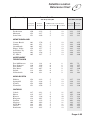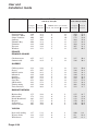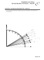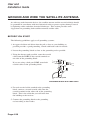
1
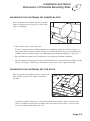
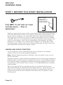
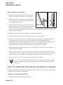
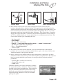
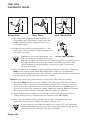
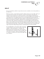
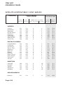
4
Installation
and Setup -A 5 Step Process
INTRODUCTION
If you do not want to install your system yourself, you can have it installed by a
professional. Ask your retailer for information about the installer in your area. (You will
be given a toll-free number. Call the toll-free number and leave a message. The installer
will call you back to set an appointment).
If you do intend to install your ExpressVu™ system yourself, this chapter provides
installation procedures. The procedures are relatively simple, but do require some skill in
construction-related tasks. Be sure to follow all warnings and cautions; they are provided
for your safety.
An optional Installation Kit is available. This Kit includes typical hardware used during
installation, and a more detailed Installation Kit Guide. Contact your ExpressVuTM dealer.
It is important that you follow all local building codes and the electrical
codes specified by your local electric company, as well as standard safety
procedures for installing and working with this type of equipment.
Improper procedures or installation can result in damage to the equipment
or the building, and harm to you. If you are not sure about whether your
installation follows these codes, contact a licensed building inspector or
electrician in your area for assistance.
Take extreme care to avoid contacting any overhead power lines, lights, and
power circuits while you are installing the satellite antenna. Contact with
any of these could prove fatal. Do not install the satellite antenna near
power lines.
See "Safety Instructions" on page iii for additional safety information.
Page 4-1
User and
Installation Guide
DISCUSSION OF POTENTIAL MOUNTING SITES
When you are surveying your property for appropriate sites for the satellite antenna, keep
in mind that you can mount the satellite antenna on a variety of surfaces: brick, cinder
block, wood, some sidings, rooftop, or a pole.
Because installing the satellite antenna may involve drilling into the wall or roof of your
building, or digging a hole and using cement, you should be very confident of the
location before beginning installation. Errors can be expensive and time-consuming.
The following guidelines apply to all mounting surfaces and locations.
WEATHER AND WIND CONSIDERATIONS
The satellite antenna has been built to withstand most kinds of weather. However,
extremely strong winds could damage the base on which the satellite antenna is mounted.
A strong wind can cause the satellite antenna to exert several hundred kilograms of
pressure on the mounting surface, so the surface must be stable and strong. Such a
mounting surface also helps ensure against movement of the satellite antenna, which
would interfere with signal reception. In general, the stronger the signal you maintain,
the better your chance of uninterrupted reception during periods of snow, rain, and heavy
cloud cover.
SOME KEY POINTS TO CONSIDER
DO’S
You should always follow these instructions to help ensure against injury to
yourself and damage to your equipment or building. See "Safety
Instructions" on page iii for further safety instructions.
• Assemble the satellite antenna in a safe location before climbing up to the mounting
location. Use caution when climbing, and when working at the mounting location.
Depending on the mounting location and size of your dish, 2 people may be required
to install the mount and antenna to your dwelling.
• Install the satellite antenna only on a solid surface such as cinderblock, brick, or solid
foundation material. If you install it on the side of a building, be sure to attach the
bolts directly to a building stud or other solid material. Use the appropriate drilling
and attachment hardware for the surface.
• Make sure you have determined the best location for the satellite antenna before
drilling the holes in your building or setting up the mounting pole. Mistakes can be
costly.
• All installations should conform to your local building and electrical codes. If you are
not sure, contact a licensed building inspector or electrician in your area to assist you.
Be aware that community covenants, if any, may have additional requirements.
Page 4-2
Installation and Setup
Discussion of Potential Mounting Sites
4
• Choose a site that is easily accessible in most weather conditions. You may need to
clean snow, ice or debris off the satellite antenna.
• Place the satellite antenna as close to the receiver as possible. We recommend using
no more than 30 meters of cable between the receiver and the satellite antenna, unless
you install a line amplifier to boost the signal.
• Consider seasonal changes. The site may appear unobstructed in the winter, but spring
and summer foliage could block the signal to the satellite antenna.
DO NOTS
You should always follow these instructions to help ensure against injury to
yourself and damage to your equipment or mounting surface. See "Safety
Instructions" on page iii for further safety instructions.
• Never install the satellite antenna under power lines.
• Do not install the satellite antenna where it can be jostled, bumped, or blocked by
people, animals, or vehicles.
• Do not install the satellite antenna where it is exposed to high winds.
• Do not try to install the satellite antenna in windy or stormy weather, particularly if
there is a chance of lightning.
• Do not attempt to fasten the satellite antenna to the mortar between bricks or cinder
blocks.
• Do not mount the satellite antenna on vinyl or aluminum siding. These materials are
structurally too weak to securely hold the satellite antenna, even with a building stud
underneath. The siding would have to be crushed, or the forces of wind and weather
over time would crush the area under the foot of the antenna mast.
• Do not mount the satellite antenna downwind of a chimney or furnace vent. Ashes
and dirt could collect on the dish and LNBF, possibly causing damage and poor
reception. If practical, locate the antenna so the dish faces away from the vent.
• Do not install the satellite antenna on stucco or imitation masonry unless the base
material is solid. Do not mount the satellite antenna on composite materials such as
strand, chip, fiber, or particle board unless the fastener attaches securely to a wall stud,
rafter, or other foundation material beneath the surface.
• Do not mount the satellite antenna on a railing, on a tile roof, or in a tree.
Page 4-3
User and
Installation Guide
MOUNTING THE ANTENNA ON BRICK
We define "brick" as a solid brick wall or other structure. This does not include brick
facing that is used on some buildings over the main structure. If you are mounting the
satellite antenna on brick facing, see "Mounting the Antenna on Siding," below.
You can mount the satellite antenna on a solid brick wall.
• The surface must be flat and even.
• The mortar between the bricks should be in good to excellent condition. The satellite
antenna foot should be mounted on several bricks. As the wind tugs on the satellite
antenna, the foot will put heavy pressure (several hundred kilograms) on those bricks
in different directions. Loose or weakened mortar may allow the bricks to shift,
changing the dish angle and reception quality, and possibly damaging the satellite
antenna and the building. The installed satellite antenna could also hasten the
deterioration of old mortar.
• To mount the satellite antenna on brick, be sure that all of the fasteners are set into the
brick, not into the mortar between the bricks. Use materials necessary to follow the
local building codes.
MOUNTING THE ANTENNA ON SIDING
We do not recommend mounting the satellite antenna on aluminum or vinyl siding.
These materials can be structurally unsound, causing eventual shifting of the dish. To
mount the satellite antenna on solid siding, be sure to follow the suggestions below.
• The surface must be flat and even. You may need to use a separator, or shim, between
the shingles to even the siding surface.
• Mount the foot on the foundation material beneath the siding surface. This may be a
building stud, cinder block, or other solid material. To locate the studs, find the
vertical line of nails where the siding is attached to the building, or use a stud finder.
Page 4-4
Installation and Setup
Discussion of Potential Mounting Sites
4
MOUNTING THE ANTENNA ON CINDER BLOCK
You can mount the satellite antenna on cinder
blocks, whether they are part of a wall or the
side of a building.
• The surface must be flat and even.
• If you are mounting the satellite antenna on a building, make sure that the surface is
true cinder block, not just a block facing over another material. If you are mounting the
satellite antenna on block facing, see "Mounting the Antenna on Siding" on page 4-4.
• Be sure that the cinder block and mortar are in good to excellent condition.
• We recommend using toggle anchors and machine bolts, inserted into the hollow of the
block, as fasteners. Other types of anchors may not have the required strength.
MOUNTING THE ANTENNA ON THE ROOF
You can mount the satellite antenna on the roof.
This usually provides the highest available
location.
• Attach the satellite antenna to a rafter beneath the roof surface. You can locate the
rafter by looking for the nails attaching the fascia board to the rafters. You can also
locate the rafters from inside the attic.
Page 4-5
User and
Installation Guide
• Be sure that the location is easily accessible in most weather conditions. You may
need to sweep off snow, remove debris, or clean dirt from the dish surface.
• To prevent the roof from leaking, you should caulk the holes, or use silicone sealant
around the holes and at the bottom of the satellite antenna foot where it contacts the
surface. Apply the sealant before you bolt the foot down tight.
• Place the antenna so it is not directly downwind from a chimney or furnace vent. Soot
can gather on the dish surface, weakening the reception. If practical, locate the
antenna so the dish faces away from the chimney.
• Do not mount the antenna on a tile roof.
MOUNTING THE ANTENNA ON WOOD
You can mount the satellite antenna on a
wooden deck, wooden beam, or other
wooden surface.
• The surface must be flat and even.
• Be sure that the wood has a solid foundation, and is secured. It should be a strong
piece that cannot be moved or jiggled.
• Do not mount the satellite antenna on a railing.
Page 4-6
Installation and Setup
Summary Of Installation
4
SUMMARY OF INSTALLATION
Following is a summary of the procedures to install and set up your ExpressVu™ system.
We recommend that you perform the procedures in the order presented.
1. Unpack the satellite antenna, receiver, and parts (see pages 4-8 through 4-10) and
the optional installation kit, if you purchased one (see page 4-9).
2. Review "What You Need to Know" (see page 4-9).
3. Connect the receiver to your TV set, and make sure the Smart Card is installed
(see page 4-28).
4. Determine the approximate location of the ExpressVu™ satellite
(see page 4-10).
5. Find the best location on your property for the satellite antenna, with a clear line
of sight to the satellite (see pages 4-10 through 4-12).
6. Assemble the satellite antenna and attach it to a solid surface (see pages 4-12 through
4-26).
7. Ground the satellite antenna, and wire it to the ExpressVu™ receiver
(see pages 4-38).
8. Aim the satellite antenna for the strongest possible signal (see pages 4-29 through
4-33).
9. Connect the receiver to an active telephone connection (see page 4-39). With the
receiver wired to the TV and the antenna properly installed, you will be able to see
the ExpressVu™ Program Guide, which tells you about available programs,
channels, and services.
10.Order your programming by calling the ExpressVu™ Customer Service Centre at
1-888-SKY-DISH (see page 4-40).
11.Wire the receiver to your other electronic equipment (see page A-13).
Page 4-7
User and
Installation Guide
STEP 1: BEFORE YOU START INSTALLATION
This is a typical
"Mount"shown
attached to a wall.
Notice that the top
portion is "Plumb".
THE KEY
} Top
TO SETTING UP YOUR
SYSTEM EASILY
– THIS
IS
IMPORTANT
The key to setting up the system is in the accurate initial setting of the vertical elevation
of the dish. The vertical elevation is the amount of tilt upwards, from horizontal, toward
the sky, which is required to “see” the satellite. This is best achieved by mounting the
dish support mast so that the top portion, to which the dish clamps attach, is as “Plumb”
as possible. That is to say: the top portion of the mount should be as perpendicular to the
earth as you can manage - this is true for wall mounting, roof mounting, any kind of
mounting. If it is “Plumb“, then, when the dish is mounted on it and the dish is tilted
upward toward the satellite at the correct vertical elevation angle, the dish can be easily
panned (East/West movements) to find the satellite.
UNPACK AND CHECK CONTENTS
As you unpack the system, confirm that all the parts are included. See "Package
Contents" below for a list of the included components.
Note: Keep the shipping materials in which these items are packed, in case you ever
need to return them.
Unpack the contents carefully. Electronic equipment can be easily damaged if bumped or
handled roughly. Examine all parts for damage that may have occurred during shipment.
If you find any damage, immediately call the location where your ExpressVu™ system
was purchased, or the Customer Service Centre at 1-888-SKY-DISH, before continuing
with installation.
The size of your dish will vary depending on the part of Canada in which you live.
The standard diameter of a ExpressVuTM dish is 60 cm, however, 76 cm, 90 cm or 1.2m
dishes are also available. If you require the large dish, we recommend that you hire a
professional to install it because installation of the 90 cm and 1.2 m dishes is a more
exacting project.
Page 4-8
Installation and Setup
Before You Start Installation
4
PACKAGE CONTENTS
• User and Installation Guide
• ExpressVu™ satellite antenna assembly
• ExpressVu™ receiver
• Accessories
❒
❒
❒
❒
❒
7.6-metre RJ11 telephone cable
2.4-metre phono (RCA) 3-connector cable
1.8-metre modulator cable
2.4-metre S-VIDEO cable (optional)
Remote control, with two (2) AAA batteries packaged separately
In addition, we provide an optional Installation Kit, which includes the necessary
hardware and cables that you would typically use during installation. Contact the
location where your ExpressVu™ system was purchased for more information, or call the
ExpressVu™ Customer Service Centre at 1-888-SKY-DISH for the location of a licensed
dealer near you.
WHAT YOU NEED TO KNOW
Because you will make modifications to the location where you mount the satellite
antenna, we suggest that you be familiar with and be able to safely perform the following
procedures.
• You should be able to use a plumb line or level to set both horizontal and vertical
surfaces. This is especially critical for vertical surfaces.
• You should know how to drill holes in the mounting surface (whether wood, brick,
cinder block, etc.).
• You should know how to drill holes and run cabling through your building. This
includes sealing the holes once the cable has been installed.
WHAT YOU NEED TO HAVE
If you did not purchase the installation kit, you will need the following materials:
• Coaxial cables and connectors (RG6 recommended up to 100ft. For longer distances
consult a installer)
• Fastening devices to attach the mount to your dwelling
• Waterproofing for the outdoor connections
• Grounding materials
• Cable ties
Page 4-9
User and
Installation Guide
You will also need some tools:
A 7/16”,1/2”, 9/16” wrench (varies with dish size)
A Phillips screwdriver
A spirit level
A drill and drill bits (masonry and wood)
A compass
INSTALL BATTERIES IN THE REMOTE
Two AAA batteries, packaged separately, are included with the remote control.
See "Install Batteries in the Remote" on page 2–4 for this procedure.
STEP 2:
FIND THE RIGHT LOCATION FOR THE DISH
The Dish must be at a location on your dwelling which gives a clear, year-round,
unobstructed “view” of the satellite and which is also free from occasional blockages due
to vehicles or passers-by.
Locating the appropriate site for your ExpressVu dish is a two step process: First, use
your compass and the satellite direction data provided in this guide, to estimate the
general direction of the satellite. Use this information to find the right spot to mount the
dish on your dwelling. Next, get more serious about the installation; confirm that your
dish has a clear unobstructed “view” of the satellite and that the dish can be mounted
securely.
ExpressVu’s current satellite is located 107.30 West Longitude. In late 1998, ExpressVu
will begin transmitting from a new, more powerful satellite to be located at 910 West
Longitude. When the new satellite becomes fully operational, all existing dishes will need
to be moved to a new position in order to acquire the new satellite signal. The movement
in question will involve a panning to left or right, and possibly tilting up or down of the
dish. Note: The “Satellite Location Table” on page 4-34 contains information on locating
the current and future satellite position.Using the figures in the these tables, it is
recommended that you select a mounting location for your dish which will allow a clear,
unobstructed line of sight to both satellites. If your circumstances prevent you from
“seeing” both satellites from one location, but you are able to “see” both satellites from
two different locations, it will be necessary to move the entire mast and dish assembly to
the new location when the new satellite becomes operational.
Page 4-10
Installation and Setup
Find The Right Location For The Dish
4
WHAT YOU WILL NEED
•
•
•
•
Compass
Level
Satellite Location Table (page 4-34)
Vertical Elevation Protractor (page 4-37)
DETERMINE DIRECTION TO THE SATELLITE
You must determine the direction the ExpressVu™ satellite from your location to help
you determine where to mount your antenna. You must have a clear line of sight from the
antenna location to the satellite. Use the following procedure to find the best location for
the antenna, while keeping in mind the considerations referenced in DISCUSSION OF
POTENTIAL SITES on page 4-2.
After you finish mounting the antenna, you will need to re-aim the dish to get the strongest
signal. Please see STEP 5: ALIGNING THE DISH on page 4-29 for this procedure.
WHERE IS IT?
Our current satellite (ANIK E2) is in a stationary position
some 40,000 km above the earth, directly above the equator
about due South from Saskatoon. To determine if you have a
clear view from your location to the satellite, look in the
direction of the correct compass heading according to the
table on page 4-34, using the information for the city
nearest you.
Facing this direction look up into the sky, at the angle above
the horizon specified in the table (vertical elevation angle)
starting on page 4-34. For example, in Calgary, look in the
Southern sky at compass heading 1530 and 310 above the
horizon. Usually, assessing whether or not you have a clear
view of the satellite is as simple as observing the southern
sky and estimating the possibility of an obstruction. Our
current satellite is in a Southeastern direction from the
Western Provinces, Southerly from the Prairies, and
Southwesterly from the Maritimes.
Finding the ExpressVu Satellite
from Calgary
ExpressVu Satellite 153
0
Page 4-11
User and
Installation Guide
To get a direction from a compass, set it on a flat, non-metal surface and
rotate it until “North” is indicated on the dial under the needle. Now sight
from the centre of the compass towards the angle of interest. From the
installation location sight a distant object such as a tree or building, so that
you have a convenient reference of the position of the satellite.
FIND A CLEAR LINE OF SIGHT
"Find a clear line of sight" means to find a location for the satellite antenna so that its
view of the orbiting satellite is unobstructed by trees, buildings, or any other obstructions.
This includes making sure that sapling trees are
The Homemade Sextant
not likely to grow up or out into the line of sight.
Also, consider seasonal changes. An unobstructed Cardboard triangle copied
from back cover
site in winter may be obstructed by foliage in
spring and summer.
Cardboard Cutout
If you need a way to determine if you have a clear
“view” to the satellite, try this procedure: Cut out a
cardboard triangle with its base about 8-10 inches
long. Make the angle of the triangle equal to the
vertical elevation angle for your location as given
in the Table (page 4-34) or simply use the triangle
as illustrated on page 4-37 as a template. Tape it to
your level as shown in the sketch. Now you have a
homemade sextant! Next, look up the edge of the
cardboard while holding the level horizontal while
aiming it at the correct compass heading. If there is
an obstruction, locate the dish elsewhere.
Level
Using
the Sextant
STEP 3: ASSEMBLING THE DISH
The following section outlines the assembly procedure for all four dish sizes: 60 cm, 76
cm, 90 cm, and 120 cm.
The overall assembly procedure is similar for all four sizes, but there are some specific
differences which are addressed in four separate sections. Please refer to the section
which is relevant to the dish size you have purchased:
•
•
•
•
Step 3.1
Step 3.2
Step 3.3
Step 3.4
Page 4-12
Assembling the 60 cm Dish
Assembling the 76 cm Dish
Assembling the 90 cm Dish
Assembling the 120 cm Dish
Installation and Setup
Assembling the 60cm Dish
4
STEP 3.1: ASSEMBLING THE 60 CM DISH
STEP 3.1A: PRE-ASSEMBLE THE PARTS (60 CM DISH)
It’s best to pre-assemble the dish indoors, so that it is all ready to place on the mast
outdoors, quickly and easily ... especially if it’s cold out.
The complete system consists of three main parts: the
dish mount, the dish assembly, and the receiver. The
mount consists of the foot (base plate) and a bent pipe
called the mast. These two parts are pre-assembled.
The dish assembly consists of the antenna, or dish,
the dish support bracket, the (LNBF) low noise
amplifier, and the LNBF support arm. The receiver is
also fully assembled.
Dish
Mount
Mast
LNBF Arm
Pre-assemble the Dish as follows:
1. Bolt the dish to the support bracket and the support
arm; there are clear instructions and pictures in the
antenna box.
Neck
Collar
2. Mount the plastic LNBF assembly bracket on the
LNBF arm as shown in the diagram. It should slide
onto the end of the LNBF arm until it is stopped by
the plastic tab. Fasten it with the screw provided.
Curved Shoe
M
3. Place the narrow neck of the LNBF into the curved
shoe of the assembly bracket then place the capture
collar over the neck and fasten it carefully and
evenly with the two screws provided. Do not
firmly tighten as further adjustments are required.
The white plastic portion of the LNBF should face
the dish.
4. Adjust the position of the LNBF to be as far back
in the collar as possible. Do this by gently pulling
the LNBF as far away from the dish as permitted
by the LNBF and collar assembly. Rotate the
LNBF so that the coaxial connectors are pointing
down. This is the “6:00 o’clock” position for the
LNBF rotation (please refer to the diagrams).
BF
LN
AR
LNBF
Bracket Stops
d sh
LNBF
LNBF ARM
5 o'clock
7 o'clock
6 o'clock
Page 4-13
User and
Installation Guide
5. Twist the angle of the LNBF slightly according to
the Table (page 4-34). In Western Canada, the
LNBF is in the 7:00 o’clock position; in Central
Canada, it is in the 6:00 o’clock position and in
Eastern Canada, it is in the 5:00 o’clock position.
Vertical Elevation
Gauge
6. Determine your specific vertical elevation from
the Table (page 4-34) and adjust the angular tilt of
the antenna so that the edge of the red mark on the
gauge is set to your vertical elevation. In our
diagram here, it is set for 38.5 degrees.
7. Lightly tighten the bolt on the gauge side of the angular pivot; leave the bolt on the
back side slightly loose.
8. Your antenna assembly is now ready to be placed on the outdoor mount assembly.
The mount for attaching the dish to the dwelling is made steel and, as a
result, it is very magnetic. If you are too close, it can adversely alter your
compass readings.
STEP 3.1B: ATTACHING THE MOUNT TO YOUR DWELLING
(60 CM DISH)
The mount should be attached to your dwelling before putting the dish assembly on it.
When fastening it to your wall or roof, etc., make sure that the top portion is “plumb”;
you can get it right by using a spirit level on both the front and side of the top piece. It is
important to affix the mount firmly to your structure with at least 4 fasteners so that the
wind will not alter the direction of the dish.
Note: Plumb means vertical in all directions. A flagpole is plumb.
90˚
WALL MOUNT
Page 4-14
90˚
HORIZONTAL MOUNT
90˚
ROOF MOUNT
Installation and Setup
Assembling the 60cm Dish
Here is how it can be done:
SIDE VIEW
4
FRONT VIEW
1. Place the mount foot on the surface location
where you intend to attach it to the structure.
2. Arrange the holes in the foot to be over solid
material and adjust the top part of the mast to
be approximately plumb.
3. Put your spirit level on the side of the pipe (see
diagram) and move the foot slightly to make the PRESS LEVEL
AGAINST MOUNT
pipe vertical. Don’t worry about getting
the pipe level in the front and back direction this will be done with the pivot arrangements after the foot is mounted.
4. Mark the location of one of the holes and remove the mount.
5. Drill the hole and attach the mount foot with the one fastener only.
6. Now, once again, position the top of the mast to be approximately plumb; then place a
level on the side of the pipe and pivot the mount foot slightly around the one
attachment and adjust the mount foot to make the pipe vertical. Once achieved, drill
the other 3 holes while the mount foot is still properly in place. (Alternatively, you can
mark the holes, remove the mount, then drill).
7. Attach the mount with the 4 fasteners; seal the holes with silicone to prevent water
damage to your dwelling.
8. Place your level on the front face of the top section of the mast and adjust the pipe to
be vertically level by pivoting around the base bracket. Tighten down the nuts on the
bracket when it is level. There are no further adjustments to make on the mount.
9. Check your work... The top of the mast should now be “plumb”!
If you have trouble fastening the mount to a surface, try mounting a solid
piece of wood to your dwelling’s surface first, then fastening the mount to
the wood.
STEP 3.1C: INSTALLING THE DISH ON THE MOUNT
(60 CM DISH)
You have installed the mount on your dwelling and you have pre-assembled the antenna
unit, ready to be installed on the mount.
There are just a few steps here:
1. Slide the antenna assembly over the mast.
2. Lightly tighten the two nuts on the back of the mast clamp, so that the antenna can
pivot in the East/West directions but not be loose.
3. You are ready to carry out the antenna alignments, as soon as the wiring in Step 3.1D
is completed.
Page 4-15
User and
Installation Guide
STEP 3.1D: CONNECTING THINGS TOGETHER (60 CM DISH)
The wiring is accomplished as follows:
1. Thread a length of coaxial cable through the dish
as shown in diagram
2. Connect the coaxial cable to the LNBF. Route
and fasten the cable in a neat, unobtrusive manner
in such a way so it cannot be damaged by accident.
Connect the opposite end of the cable to your
receiver, to the connector marked “Satellite In”.
3. To prevent long term moisture damage, cover all
outdoor coaxial connections with weather boots.
4. See page 4-38 for instructions concerning safety grounding.
The assembly and mounting of the 60 cm Dish is complete.
Proceed to page 4-28 Installing the Receiver.
STEP 3.2: ASSEMBLING THE 76 CM DISH
STEP 3.2A: PRE-ASSEMBLE THE PARTS (76 CM DISH)
It’s best to pre-assemble the dish indoors, so that it is all ready to place on the mast
outdoors, quickly and easily ... especially if it’s cold out.
The complete system consists of three main parts: the dish mount, the dish assembly, and
the receiver. The mount consists of the foot (base plate) and a bent pipe called the mast.
These two parts are pre-assembled. The dish assembly consists of the antenna, or dish,
the dish support bracket, the (LNBF) low noise amplifier, and the LNBF support arm.
The receiver is also fully assembled.
Pre-assemble the Dish as follows:
Identify the 5 main components of the dish assembly.
(A)
(B)
(C)
(D)
(E)
Dish
LNBF feed support arm
Antenna mounting bracket
LNBF mounting bracket
LNBF
(A)
(B)
(C)
1. Slide the LNBF feed support arm onto the antenna mounting
bracket and attach it with the two bolts/nuts provided.
2. Attach the Dish to the antenna mounting bracket with the 4 flat
head bolts provided.
Page 4-16
(D)
(E)
Installation and Setup
Assembling the 76cm Dish
4
3. Slide the plastic LNBF mounting bracket on to the end of the
LNBF feed support arm. Attach with screws provided.
4. Place the narrow neck of the LNBF into the curved shoe of the
LNBF mounting bracket, then place the capture collar over the
neck and fasten it carefully and evenly with the two screws
provided. Do not firmly tighten as further adjustments are
required. Mount the capture collar so that the numbers on it
read correctly when viewed from the back, looking into the
dish. Line up the marker line, labeled “up” on the back of the
LNFB with the number “9” on the scale of the LNBF collar.
STAND PIPE
BRACKET BOLTS
5. Twist the angle of the LNBF slightly so that the marker line,
lines up with the Polarization Angle stated in the Table (page
4-34). Lightly tighten the two screws on the collar.
ELEVATION MOUNT
BRACKET BOLTS
VERTICAL ELEVATION GAUGE
COLLAR
6. Determine your specific vertical elevation from the Table (page
4-34) and adjust the angular tilt of the antenna so that the point
of the mark on the gauge is set to your vertical elevation. In
our diagram here, it is set for 50.0 degrees.
CURVED SHOE
LNBF ARM
7. Lightly tighten the bolt on the gauge side of the angular pivot;
leave the bolt on the back side slightly loose.
8. Your antenna assembly is now ready to be placed on the
outdoor mount assembly.
The mount for attaching the dish to the dwelling is
made of steel and, as a result, it is very magnetic. If
you are too close, it can adversely alter your compass readings.
STEP 3.2B: ATTACHING THE MOUNT TO YOUR DWELLING
(76 CM DISH)
The mount should be attached to your dwelling before putting the dish assembly on it.
When fastening it to your wall or roof, etc., make sure that the top portion is “plumb”;
you can get it right by using a spirit level on both the front and side of the top piece. It is
important to affix the mount firmly to your structure with at least 4 fasteners so that the
wind will not alter the direction of the dish.
Note: Plumb means vertical in all directions. A flagpole is plumb.
90˚
WALL MOUNT
90˚
90˚
HORIZONTAL MOUNT
ROOF MOUNT
Page 4-17
User and
Installation Guide
Here is how it can be done:
SIDE VIEW
FRONT VIEW
1. Place the mount foot on the surface location
where you intend to attach it to the structure.
2. Arrange the holes in the foot to be over solid
material and adjust the top part of the mast to
be approximately plumb.
PRESS LEVEL
3. Put your spirit level on the side of the pipe (see
AGAINST MOUNT
diagram) and move the foot slightly to make the
pipe vertical. Don’t worry about getting the
pipe level in the front and back direction -this will be done with the pivot arrangements
after the foot is mounted.
4. Mark the location of one of the holes and remove the mount.
5. Drill the hole and attach the mount foot with the one fastener only.
6. Now, once again, position the top of the mast to be approximately plumb; then place a
level on the side of the pipe and pivot the mount foot slightly around the one
attachment and adjust the mount foot to make the pipe vertical. Once achieved, drill
the other holes (3 or more) while the mount foot is still properly in place.
(Alternatively, you can mark the holes, remove the mount, then drill).
7. Attach the mount with the 4 fasteners; seal the holes with silicone to prevent water
damage to your dwelling.
8. Place your level on the front face of the top section of the mast and adjust the pipe to
be vertically level by pivoting around the base bracket. Tighten down the nuts on the
bracket when it is level. There are no further adjustments to make on the mount.
9. Check your work ... The top of the mast should now be “plumb”!
If you have trouble fastening the mount to a surface, try mounting a solid
piece of wood to your dwelling’s surface first, then fastening the mount to
the wood.
STEP 3.2C: INSTALLING THE DISH ON THE MOUNT (76 CM DISH)
You have installed the mount on your dwelling and you have pre-assembled the antenna
unit, ready to be installed on the mount.
There are just a few steps here:
1. Slide the antenna assembly over the mast.
Page 4-18
Installation and Setup
Assembling the 76cm Dish
4
2. Lightly tighten the two nuts on the back of the mast clamp, so that the antenna can
pivot in the East/West directions but not be loose.
3. You are ready to carry out the antenna alignments, as soon as the wiring in Step 3.2D
is completed.
STEP 3.2D: CONNECTING THINGS TOGETHER (76 CM DISH)
The wiring is accomplished as follows:
1. Thread a length of coaxial cable through the dish as
shown in diagram.
2. Connect the coaxial cable to the LNBF. Route
and fasten the cable in a neat, unobtrusive manner
in such a way so it cannot be damaged by accident.
Connect the opposite end of the cable to your
receiver, to the connector marked “Satellite In”.
3. To prevent long term moisture damage, cover all
outdoor coaxial connections with weather boots.
To Ground
4. See page 4-38 for instructions concerning safety
grounding.
To Grounding Block
The assembly and mounting of the 76 cm Dish is complete.
Proceed to page 4-28 Installing the Receiver.
STEP 3.3: ASSEMBLING THE 90 CM DISH
STEP 3.3A: PRE-ASSEMBLE THE PARTS (90 CM DISH)
It’s best to pre-assembly the dish indoors, so that it is
all ready to place on the mast outdoors, quickly and
easily ... especially if it’s cold out.
DISH
The complete system consists of three main parts: the
dish mount, the dish assembly, and the receiver. The
mount consists of the foot (base plate) and a bent pipe
called the mast. The dish assembly consists of the
antenna, or dish, the dish support bracket, the (LNBF)
low noise amplifier, and the LNBF support arm. The
receiver is also fully assembled.
LNBF
LNBF ARM
MOUNT MAST
Page 4-19
User and
Installation Guide
Pre-assemble the Dish as follows:
1. Assemble the dish as indicated in the instructions
which are included in the antenna box.
2. Mount the plastic LNBF assembly bracket on the
LNBF arm as shown in the diagram. It should
slide onto the end of the LNBF arm until it is
stopped by the plastic tab. Fasten it with the screw
provided.
3. Place the narrow neck of the LNBF into the curved
shoe of the assembly bracket then place the
capture collar over the neck and fasten it carefully
and evenly with the two screws provided. Do not
firmly tighten as further adjustments are required.
The white plastic portion of the LNBF should face
the dish.
4. Adjust the position of the LNBF to be as far back
in the collar as possible. Do this by gently pulling
the LNBF as far away from the dish as permitted
by the LNBF and collar assembly. Rotate the
LNBF so that the coaxial connectors are pointing
down. This is the “6:00 o’clock” position for the
LNBF rotation (please refer to the diagrams).
AR
M
LNBF
Bracket Stops
d sh
LNBF
LNBF ARM
5 o'clock
7 o'clock
6 o'clock
VERTICAL
ELEVATION
GAUGE
VERTICAL
ELEVATION
GAUGE
10 20 30 40
50
60
70
10 20 30 40
50
60
70
80
90
7. Lightly tighten the two bolts located in the curved
slots on the mast head. Leave the pivot bolt
slightly loose.
BF
LN
90
6. Determine your specific vertical elevation from the
Table (page 4-34) and adjust the angular tilt of the
antenna so that the centre of the top bolt on the
Mast Head Clamp lines up with your vertical
elevation position on the Mast Head elevation
gauge. In our diagram here, it is set for 50 degrees.
Curved Shoe
80
5. Twist the angle of the LNBF slightly according to
the Table (page 4-34). In Western Canada, the
LNBF is in the 7:00 o’clock position; in Central
Canada, it is in the 6:00 o’clock position and in
Eastern Canada, it is in the 5:00 o’clock position.
Neck
Collar
8. Your antenna assembly is now ready to be placed
on the outdoor mount assembly.
The mount for attaching the dish to the dwelling is made of steel and, as a
result, it is very magnetic. If you are too close, it can adversely alter your
compass readings.
Page 4-20
Installation and Setup
Assembling the 90cm Dish
4
STEP 3.3B: ATTACHING THE MOUNT TO YOUR DWELLING
(90 CM DISH)
The mount should be attached to your dwelling before putting the dish assembly on it.
When fastening it to your wall or roof, etc., make sure that the top portion is plumb”.
You can get it right by using a spirit level on both the front and side of the top piece.
It is important to affix the mount firmly to your structure with the appropriate fasteners
so that the wind can’t move it. The dish support mounting assembly requires an area of
approximately 9 square feet to accommodate the mast mount foot and the two support
struts.
Note: Plumb means vertical in all directions. A flagpole is plumb.
90˚
90˚
90˚
WALL MOUNT
HORIZONTAL MOUNT
ROOF MOUNT
Here is how it can be done:
FRONT VIEW
PRESS LEVEL
AGAINST MOUNT
1. Place the mount foot on the surface location
where you intend to attach it to the structure.
2. Mark the location of one of the 2 holes and
remove the mount.
3. Drill the hole and attach the mount foot with
the one fastener only.
Mountfoot
Mountfoot
4. Place a spirit level on the top and side of the
foot and pivot the foot to make it level and plumb. Drill the other hole while the
mount foot is still properly in place. (Alternatively, you can mark the hole, remove
the mount, then drill)
5. Attach the mount with the 2 fasteners; seal the holes with silicone to prevent water
damage to your dwelling.
6. Install the mast to the mount foot using the supplied fastener. Orientate the mast so
that the short curved portion will face vertically.
7. Place a spirit level on the front face of the short curved portion of the mast and adjust
the mast to a vertical position. Tighten the mast mounting bolt.
Page 4-21
User and
Installation Guide
8. Attach the two struts to the mast with the supplied hardware. Tighten the bolt for a
snug fit that still allows some slight movement of the struts.
9. Position the foot of each strut squarely on the mounting surface and mark the holes
for drilling. Prior to drilling the strut holes, confirm with the spirit level that the mast
is still vertical. This is a critical check to ensure proper alignment.
10. Drill the holes while the strut feet are still properly in place. (Alternatively, you
can mark the holes, move the struts slightly, then drill.)
11. Attach the mount with the 4 fasteners; seal the holes with silicone to prevent water
damage to your dwelling.
12. Tighten the strut attachment bolt which was installed in step 8. Place the level on
front face of the short curved portion of the mast to confirm that the mast is still
vertical. There are no further adjustments to make to the mount.
If you have trouble fastening the mount to a surface, try mounting a solid
piece of wood to your dwelling’s surface first, then fastening the mount to
the wood.
STEP 3.3C: INSTALLING THE DISH ON THE MOUNT
(90 CM DISH)
You have installed the mount on your dwelling and you have pre-assembled the antenna
unit, ready to be installed on the mount.
There are just a few steps here:
1. Slide the antenna assembly over the mast.
2. Lightly tighten the four nuts on the back of the mast clamp, so that the antenna can
pivot in the East/West directions but not be loose.
3. You are ready to carry out the antenna alignments, as soon as the wiring in Step 3.3D
is completed.
STEP 3.3D: CONNECTING THINGS TOGETHER (90 CM DISH)
The wiring is accomplished as follows:
1. Thread a length of coaxial cable through the mast pipe and mast clamp as shown
in the diagram.
Page 4-22
Installation and Setup
Assembling the 90cm Dish
4
2. Route the coaxial cable along the back
side of the feed support tube as shown in the
diagram.
3. Connect the coaxial cable to the LNBF. Route
and fasten the cable in a neat, unobtrusive
manner in such a way so it cannot be damaged
by accident. Connect the opposite end of the
cable to your receiver, to the connector marked
“Satellite In”.
COAXIAL CABLE
4. To prevent long term moisture damage, cover all outdoor coaxial connections with
weather boots.
5. See page 4-38 for instructions concerning safety grounding.
The assembly and mounting of the 90 cm Dish is complete.
Proceed to page 4-28 Installing the Receiver.
STEP 3.4: ASSEMBLING THE 120 CM DISH
STEP 3.4A: PRE-ASSEMBLE THE PARTS (120 CM DISH)
It’s best to pre-assembly the dish indoors, so that it is all ready to place on the mast
outdoors, quickly and easily ... especially if it’s cold out.
The complete system consists of three main parts: the dish
mount, the dish assembly, and the receiver. The mount
consists of the foot (base plate) and a bent pipe called the
mast. The dish assembly consists of the antenna, or dish,
the dish support bracket, the (LNBF) low noise amplifier,
and the LNBF support arm. The receiver is also fully
assembled.
DISH
LNBF
SUPPORT
STRUTS
LNBF ARM
Pre-assemble the Dish as follows:
1. Assemble the dish as indicated in the instructions which
are included in the antenna box.
2. Mount the plastic LNBF assembly bracket on the LNBF
arm as shown in the diagram. It should slide onto the
end of the LNBF arm until it is stopped by the plastic tab.
Fasten it with the screw provided.
3. Place the narrow neck of the LNBF into the curved
shoe of the assembly bracket then place the capture
collar over the neck and fasten it carefully and evenly
MOUNT MAST
Neck
Collar
Curved Shoe
RM
A
BF
LN
LNBF
Bracket Stops
Page 4-23
User and
Installation Guide
with the two screws provided. Do not firmly
tighten as further adjustments are required. The
white plastic portion of the LNBF should face
the dish.
4. Adjust the position of the LNBF to be as far back
in the collar as possible. Do this by gently pulling
the LNBF as far away from the dish as permitted
by the LNBF and collar assembly. Rotate the
LNBF so that the coaxial connectors are pointing
down. This is the “6:00 o’clock” position for the
LNBF. (Please see the accompanying diagrams)
5 o'clock
7 o'clock
6 o'clock
VERTICAL
ELEVATION
GAUGE
VERTICAL
ELEVATION
GAUGE
10 20 30 40
50
60
70
90
6. Determine your specific vertical elevation from the
Table (page 4-34) and adjust the angular tilt of the
antenna so that the centre of the top bolt on the
Mast Head Clamp lines up with your vertical
elevation position on the Mast Head elevation
gauge. In our diagram here, it is set for 50 degrees.
LNBF
LNBF ARM
80
5. Twist the angle of the LNBF slightly according to
the Table (page 4-34). In Western Canada, the
LNBF is in the 7:00 o’clock position; in Central
Canada, it is in the 6:00 o’clock position and in
Eastern Canada, it is in the 5:00 o’clock position.
d sh
10 20 30 40
50
60
70
80
90
7. Lightly tighten the two bolts located in the curved
slots on the mast head. Leave the pivot bolt
slightly loose.
8. Your antenna assembly is now ready to be placed
on the outdoor mount assembly.
The mount for attaching the dish to the dwelling is made of steel and, as a
result, it is very magnetic. If you are too close, it can adversely alter your
compass readings.
STEP 3.4B: ATTACHING THE MOUNT TO YOUR DWELLING
(120 CM DISH)
The mount should be attached to your dwelling before putting the dish assembly on it.
When fastening it to your wall or roof, etc., make sure that the top portion is “plumb”;
you can get it right by using a spirit level on both the front and side of the top piece. It is
important to affix the mount firmly to your structure with the appropriate fasteners so that
the wind can’t move it. The dish support mounting assembly requires an area of
approximately 9 square feet to accommodate the mast mount foot and the two support
struts.
Note: Plumb means vertical in all directions. A flagpole is plumb.
Page 4-24
Installation and Setup
Assembling the 120cm Dish
4
90˚
90˚
90˚
WALL MOUNT
HORIZONTAL MOUNT
Here is how it can be done:
ROOF MOUNT
FRONT VIEW
PRESS LEVEL
AGAINST MOUNT
1. Place the mount foot on the surface location
where you intend to attach it to the
structure.
2. Mark the location of one of the 2 holes and
remove the mount.
3. Drill the hole and attach the mount foot with
the one fastener only.
Mountfoot
Mountfoot
4. Place a spirit level on the top and side of the
foot and pivot the foot to make it level and plumb. Drill the other hole while the
mount foot is still properly in place. (Alternatively, you can mark the hole, remove the
mount, then drill)
5. Attach the mount with the 2 fasteners; seal the holes with silicone to prevent water
damage to your dwelling.
6. Install the mast to the mount foot using the supplied fastener. Orientate the mast so
that the short curved portion will face vertically.
7. Place a spirit level on the front face of the short curved portion of the mast and adjust
the mast to a vertical position. Tighten the mast mounting bolt.
8. Attach the two struts to the mast with the supplied hardware. Tighten the bolt for a
snug fit that still allows some slight movement of the struts.
9. Position the foot of each strut squarely on the mounting surface and mark the holes
for drilling. Prior to drilling the strut holes, confirm with the spirit level that the mast
is still vertical. This is a critical check to ensure proper alignment.
10. Drill the holes while the strut feet are still properly in place. (Alternatively, you
can mark the holes, move the struts slightly, then drill.)
11.Attach the mount with the 4 fasteners; seal the holes with silicone to prevent water
damage to your dwelling.
12. Tighten the strut attachment bolt which was installed in step 8. Place the level on
the front face of the short curved portion of the mast to confirm that the mast is still
vertical. There are no further adjustments to make to the mount.
Page 4-25
User and
Installation Guide
If you have trouble fastening the mount to a surface, try mounting a solid
piece of wood to your dwelling’s surface first, then fastening the mount to
the wood.
STEP 3.4C: INSTALLING THE DISH ON THE MOUNT
(120 CM DISH)
You have installed the mount on your dwelling and you have pre-assembled the antenna
unit, ready to be installed on the mount.
There are just a few steps here:
1. Slide the antenna assembly over the mast.
2. Lightly tighten the four nuts on the back of the mast clamp, so that the antenna can
pivot in the East/West directions but not be loose.
3. You are ready to carry out the antenna alignments, as soon as the wiring in Step 3.4D
is completed.
STEP 3.4D: CONNECTING THINGS TOGETHER (120 CM DISH)
The wiring is accomplished as follows:
1. Thread a length of coaxial cable through
the mast pipe and mast clamp as shown in the
diagram.
2. Route the coaxial cable along the back
side of the feed support tube as shown in the
diagram.
COAXIAL CABLE
3. Connect the coaxial cable to the LNBF. Route
and fasten the cable in a neat, unobtrusive manner in such a way so it cannot be
damaged by accident. Connect the opposite end of the cable to your receiver, to the
connector marked “Satellite In”.
4. To prevent long term moisture damage, cover all outdoor coaxial connections with
weather boots.
5. See page 4-38 for instructions concerning safety grounding.
The assembly and mounting of the 120 cm Dish is now complete.
Proceed to page 4-28 Installing the Receiver.
Page 4-26
Installation and Setup
Installing One, Two, or More Receivers
4
STEP 4: INSTALLATION: ONE, TWO, OR
MORE RECEIVERS
Note: The procedures in this Guide assume you are installing only one receiver. If you
want to use this receiver in a setup of two or more receivers, you must change the
procedures as follows. If you have already installed one or more receivers and want to
install another receiver, you may need to modify the setup.
In Installing the Antenna Mount on page 4-2 through 4-7, you must use a two-output
LNBF and attach two coaxial cables to the LNBF. .
In Attaching the Cable to the Grounding Block on page 4-38, you must route both
coaxial cables from the LNBF to the grounding block. You must route two coaxial cables
from the grounding block into your building.
In Connecting the Receiver to a Telephone Line on page 4-39, you must connect each
receiver in the setup to an active telephone connection if you want to buy pay per view
programs using any receiver in the setup. You must set up each receiver for the type of
telephone system you have.
In Ordering Your Programming on page 4-40, you must make sure that each receiver
has its Smart Card installed, and authorize services for each receiver by calling Customer
Service.
In Wiring the System Together on page A-13, you must do the following:
If you want to set up two receivers, you must route each coaxial cable from the LNBF
to its own receiver. You cannot connect two receivers to the same cable (for example, by
using a line splitter), because the two receivers would interfere with one another during
channel selection.
If you want to set up more than two receivers, you will need additional equipment.
Contact your local satellite television dealer or Customer Service for assistance.
Page 4-27
User and
Installation Guide
INSTALLING THE RECEIVER
Connect the output of the satellite receiver to your TV as described in the ExpressVu
User Manual, and turn on the ExpressVu receiver. Use your new remote control to carry
out the following steps (the remote control operation is fully described in the User
Manual). Note that the ExpressVu receivers are configured at the factory for English
language operation. French language operation is available after the dish is aligned and
the initial software download is complete.
See “Wiring Setups” on page A-13 for suggested wiring configurations.
1. Ensure your Smart Card is installed in the receiver. If your Smart Card came in a
separate package, you need to install it into the Smart Card slot in the receiver.
The receiver will work only with the correct Smart Card installed.
You must use the Smart Card that was provided with your receiver.
• Open the access door on the front panel of
the receiver by gently pulling on the left
edge.
• Unwrap the Smart Card, and insert it
face up.
• Make sure the Smart Card is firmly seated
in the slot.
• Close the access door.
2. Power on the receiver.
Page 4-28
Installation and Setup
Aligning The Dish
4
STEP 5: ALIGNING THE DISH
This is the final step to be completed before ordering your program package. If your
antenna mast is plumb, it can be accomplished very quickly; however, be patient with the
adjustments, as this step can be tricky.
The process of aligning the dish involves two steps. First, you must find the satellite to
obtain a reading on the signal strength bar. Once this is accomplished, you fine adjust the
dish pointing for maximum signal strength and obtain a solid locked signal. Finding the
satellite is the most challenging of the two operations.
If you can see and hear your television from where your dish is mounted, the dish
alignment can be carried out easily by one person.
The adjustment of the antenna is usually accomplished by two people. One person will be
positioning the antenna, while the other person provides information about the effect of
the adjustments by watching the signal strength bar on the television. These two people
must be able to communicate, in order to obtain a peak signal level. This communication
can be achieved by using a cell phone and a house phone, two walkie-talkies, a baby
monitoring system or even shouting. We suggest the following procedure:
1. Make sure that the Vertical Elevation has been set according to the table (page 4-37).
2. Ensure the LNBF twist position is correct according to the table (page 4-37).
3. Point the antenna in the direction of the satellite, as described earlier in Step 2, with a
compass. For reference, mark this starting point on the antenna clamp and mast with
a pencil.
4. Power on the receiver.
Remote
Buttons
Menu Options
6. Press the Menu button to open the
Main Menu.
7. Select the System Setup option.
8. Select the Installation option.
Page 4-29
User and
Installation Guide
9. Select the Point Dish and Signal
Strength option.
You will now see the Point Dish and Signal Strength menu.
10.You must now enter the correct number transponder. If you live East of the
Manitoba/Ontario boundary, use your cursor controls to enter no.18 in the transponder
box on the screen. If you live West of the Manitoba/Ontario boundary, use your cursor
controls to enter no.21 in the transponder box on the screen.
18
11. Now you are ready to carry out the alignment of your dish.
Ignore the Zip code box, the azimuth & elevation readings. These are not used in Canada
Avoid positioning yourself directly in front of the satellite antenna while
aiming it, as your body may block much or all of the satellite signal.
Note: The signal strength indicator will turn from red to green and audio tone will
increase in pitch as you get closer to optimizing the dish; it is important to continue
adjustments until the absolute maximum signal strength is obtained, to ensure the most
reliable signal possible in all weather conditions.
Page 4-30
Installation and Setup
Aligning The Dish
4
Mast Head
Clamp Bolts
Mast Head
Clamp Bolts
Mast Head
Clamp Bolts
90˚
90˚
60cm Dish
76cm Dish
90 & 120cm Dish
12. Now that the receiver has been setup to display the correct screen you are
ready to adjust the dish to find the satellite. If a signal level is not indicated on the
signal strength bar, loosen the mast head clamp bolts slightly and pan the dish a tiny
bit in one direction and remove your hands from it. Keep doing this, in very small
increments, until you swing the dish about 10 degrees. The system takes a second to
display the signal strength, so you must pause between adjustments. Your partner at
the TV set should inform you at each step if there is an indication on the meter. The
conversation usually goes something like this:
“ Ok, I moved it”
“ No Change”
“OK, I moved it some more”
“ Hold it ... I see something on the meter ... , move it some more”
“ Ok I moved it some more, any change ?”
“ Yes ... It’s getting better”
... and so it goes
13. If you don’t find it in the one direction, rotate the antenna back to the marked
position and carry out the procedure outlined above again—this time with the same
small movements in the opposite direction.
14. Once a signal level is indicated on the signal strength bar, it means that you have
found the satellite and you may proceed with signal level optimization. The objective
here is to obtain the highest percentage of signal possible by adjusting all three
parameters:
• Panning (East and West movements)
• Vertical Elevation, and
• LNBF twist
Continue adjusting your signal strength by panning
the antenna bit by bit to obtain the highest reading
possible on the signal strength meter. Once achieved,
snug the horizontal adjustment bolts on the clamp,
loosen the vertical elevation adjustment bolts and
adjust the dish up and down, bit by bit, to further
peak up the signal.
Page 4-31
User and
Installation Guide
Vertical
Elevation
Bolts
Vertical
Elevation
Bolts
Vertical
Elevation
Bolts
90˚
60cm Dish
90˚
76cm Dish
90 & 120cm Dish
15. Once the signal is optimized for East/West and
Vertical Elevation adjustments, gently rotate the
LNBF within the shoe to attempt to receive an
even higher signal.
16. At the receiver change the transponder to 11 and
repeat steps 14 & 15. until the signal strength level
is as high as possible.
Remember: very small adjustments - less TYPICAL LNBF ASSEMBLY
than one degree are required at this point.
You need to adjust the dish until your signal strength for transponder 11 is at
least 50%. If under clear skies you cannot consistently get at least 50%
signal strength on your transponder 11 you may require a larger dish.
Contact your dealer.
17. Now that you have an optimized signal, tighten down all nuts and screws. Select the
Save option on the screen. Mark the final locations of the mast and mounting
brackets with a permanent marker—this will assist you later if you have to realign the
antenna because of movement due to wind or weather.
Note: Do not scratch the painted surface to mark them. This will cause rusting.
18. When the Save option is selected, another screen will appear that tells you not to
disturb the receiver, and that it is downloading software. The receiver is retrieving
software from the satellite necessary for it to run. You can select the Ok option, or
you can just wait for the download to finish. Other than selecting Ok, do not disturb
the receiver until the download finishes. This may take a few minutes.
19. Once the download is complete you are ready to order your program package by
calling the ExpressVuTM Customer Service Centre at1-888-SKY-DISH.
20. If you want the ExpressVu™ system menus to appear in French, follow the
instructions in the section “Change Languages” on page 3-6.
If your efforts do not result in reception of a signal at all, most likely the
vertical adjustments are incorrect. Try changing the vertical angle in steps
of 10 on the gauge, then repeat the above procedure.
Page 4-32
Installation and Setup
Help
4
HELP
If you can’t find the satellite or suspect that your mast assembly is not exactly plumb, try
the following:
With your compass, aim the dish toward the satellite to the best of your ability. Now, put
your spirit level vertically across the dish, as shown in the diagram, and adjust the
antenna on the elevation pivot so that the antenna is vertical. In this position note the
reading on the elevation gauge, this is the base vertical angle (BV) of your installation. If
your antenna mast was perfectly plumb, the gauge would read 22.50. Determine the
difference between your BV angle and the angle of 22.50. This difference represents the
vertical correction factor which is required for your installation. If your BV angle is
greater than 22.50 , add the correction factor to your Vertical Elevation from the Table
(page 4-37) to produce your revised elevation angle. If your BV angle is less than 22.50,
subtract the correction factor from your Vertical Elevation from the table to produce your
revised elevation angle. Now, set the antenna’s vertical position to the revised elevation
angle and proceed with panning the dish as outlined in Step 12 of the procedure.
As an example here: if your “BV” angle is measured
to be 20.5 degrees and you live in Calgary where the
satellite’s vertical elevation is 31.2 degrees, the
difference between your BV angle and 22.50 (your
correction factor) is 2.0 degrees. Since your BV angle
is less than 22.5 degrees, subtract 2.0 degrees from
31.2 degrees to obtain your revised Vertical Elevation
of 29.2 degrees.
Page 4-33
User and
Installation Guide
SATELLITE LOCATION TABLE (“LOOK” ANGLES)
Community
Current Satellite
Anik E2 (at 107.30)WL
Compass
Vertical
Direction
Elevation
Future DBS (at 910)WL
LNBF Rotation (Clock Hour)
60, 90, 120 cm Dish
76 cm Dish
Compass
Vertical
Direction
Elevation
ALBERTA
Calgary
Drumheller
Edmonton
Grande Prairie
Grimshaw
Lethbridge
Lloydminster
Medicine Hat
Slave Lake
153
155
153
144
145
156
160
159
150
31.2
30.9
28.6
26.2
25.3
32.8
29.1
32.5
26.6
6
6
6
6
6
6
6
6
6
8
9
9
8
8
9
9
9
8
133
135
134
125
126
135
140
139
131
27.6
27.7
25.4
22.3
21.8
29.3
26.7
29.6
23.4
136
151
136
140
143
145
131
138
139
129
139
139
30.1
32.7
21.9
24.8
30.7
31.6
25.4
31.4
26.8
24.5
31.5
32.3
6
6
6
6
6
6
6
6
6
7
6
6
8
8
8
8
8
8
8
8
8
7
8
8
118
131
119
122
124
125
113
114
117
120
113
120
24.1
28.5
17.9
20.7
25.7
26.7
19.6
21.5
20.8
22.0
19.2
25.8
196
181
178
186
188
22.3
31.0
28.3
25.9
32.0
6
6
6
6
6
10
10
9
10
10
177
160
158
166
167
23.2
30.8
27.8
26.2
32.5
251
22.2
5
12
234
30.0
BRITISH COLUMBIA
Campbell River
Cranbrook
Fort Nelson
Fort St. John
Kamloops
Kelowna
Kitimat
Nanaimo
Prince George
Prince Rupert
Vancouver
Victoria
MANITOBA
Churchill
Dauphin
The Pas
Thompson
Winnipeg
NEW BRUNSWICK
Bathurst
Page 4-34
Satellite Location
Reference Chart
Community
4
Current Satellite
Anik E2 (at 107.30)WL
Compass
Vertical
Direction
Elevation
Edmunston
Fredericton
Moncton
Saint John
Future DBS (at 910)WL
LNBF Rotation (Clock Hour)
60, 90, 120 cm Dish
76 cm Dish
Compass
Vertical
Direction
Elevation
248
250
252
251
23.8
23.9
22.7
24.0
5
5
5
5
12
12
12
12
230
232
235
233
31.2
31.9
31.0
32.3
261
263
262
259
251
262
265
17.0
15.1
16.7
15.7
19.1
15.6
14.7
5
5
5
5
5
5
5
12
12
13
12
12
12
13
244
248
246
243
234
246
249
25.5
24.0
26.0
22.9
25.5
24.2
24.0
118
136
153
145
118
146
11.4
19.0
21.8
20.7
10.8
19.1
6
6
6
6
6
6
8
8
9
9
8
9
101
118
134
127
101
128
7.5
15.7
19.7
18.0
7.2
16.8
254
253
258
251
22.9
22.6
20.0
25.0
5
5
5
5
13
12
13
12
237
236
241
233
31.8
31.1
28.9
33.6
227
219
194
234
224
209
228
235
232
29.3
28.7
31.6
30.5
33.9
30.9
30.1
29.1
29.5
5
5
6
5
5
5
5
5
5
11
11
10
12
12
11
11
12
12
207
199
173
213
203
188
207
215
212
34.4
32.6
32.8
37.0
39.4
33.7
35.5
35.5
35.5
NEWFOUNDLAND
Corner Brook
Gander
Grand Bank
Happy Valley
Labrador City
Springdale
St. John’s
NORTHWEST
TERRITORIES
Fort McPherson
Fort Simpson
Fort Smith
Hay River
Inuvik
Yellowknife
NOVA SCOTIA
Halifax
Springhill
Sydney
Yarmouth
ONTARIO
Cobalt
Hearst
Kenora
Kingston
London
Nipigon
North Bay
Ottawa
Pembroke
Page 4-35
User and
Installation Guide
Community
Current Satellite
Anik E2 (at 107.30)WL
Compass
Vertical
Direction
Elevation
Peterborough
Sault Ste. Marie
Sioux Lookout
Sudbury
Thunder Bay
Timmins
Toronto
Windsor
Future DBS (at 910)WL
LNBF Rotation (Clock Hour)
60, 90, 120 cm Dish
76 cm Dish
Compass
Vertical
Direction
Elevation
230
217
200
225
206
224
228
221
31.3
31.9
30.7
30.6
31.8
29.0
32.4
35.3
5
5
6
5
5
5
5
5
12
11
10
11
11
11
12
11
210
196
179
204
185
204
207
199
37.4
36.1
32.6
35.6
34.4
33.6
38.3
40.5
255
254
21.7
21.9
5
5
12
12
237
236
30.2
30.3
238
253
236
239
243
247
251
242
229
241
24.8
20.7
28.1
28.0
25.8
23.2
20.8
27.2
29.6
26.8
5
5
5
5
5
5
5
5
5
5
11
12
12
12
12
12
12
12
11
12
219
236
216
220
224
229
233
223
208
222
30.6
28.4
34.3
34.8
32.8
30.3
27.9
34.4
35.0
33.7
175
178
163
171
167
165
29.4
32.3
29.7
32.1
30.4
32.4
6
6
6
6
6
6
9
9
9
9
9
9
155
156
143
150
146
144
28.7
31.6
27.6
30.8
28.6
30.2
117
128
122
13.3
19.5
17.3
6
6
6
8
8
8
100
111
105
8.4
14.9
12.1
PRINCE
EDWARD ISLAND
Charlottetown
Summerside
QUEBEC
Chibougamau
Gaspé
Mont-Laurier
Montréal
Québec
Rimouski
Sept-Îles
Sherbrooke
Témiscaming
Trois-Rivières
SASKATCHEWAN
Hudson Bay
Moosomin
North Battleford
Regina
Saskatoon
Swift Current
YUKON
Dawson Landing
Watson Lake
Whitehorse
Page 4-36
Installation and Setup
Vertical Elevation Protractor - Anik E2
4
VERTICAL ELEVATION PROTRACTOR - ANIK E2
Use the Satellite location chart and this protractor to determine your dish elevation
measurement.
°
.3
5
3
°
.4 .5°
or
2
s
1
3
d
in nto er 3
°
W ro uv
8.0
To nco al 2
Va ntre
.0°
Mo
23
x
a
lif
°
Ha
17.4
e
s
r
o
iteh
.6°
Wh
's 14
n
h
o
St. J
10.9°
Inuvik
90
80
70
60
50
40
30
20
10
0
Page 4-37
User and
Installation Guide
GROUND AND WIRE THE SATELLITE ANTENNA
As with any such electronic devices, the satellite antenna and the coaxial cable(s) should
be grounded in accordance with local electrical codes to protect against damage caused
by lightning strikes and other electrical discharges. This section provides some
suggestions on grounding both satellite antennae and the cable.
BEFORE YOU START
The following guidelines apply to all grounding systems:
1. A copper-clad iron rod driven into the soil as close to your building as
possible provides a good grounding. Check with local codes for details.
2. Locate the grounding block as close to the grounding rod as possible.
3. Using the shortest path possible, route the coaxial
cable from the LNBF to the coaxial terminal on
one side of the grounding block.
If you are using a dual-port LNBF, route both
coaxial cables to the grounding block.
To Grounding Rod
GROUNDING BLOCK WITH LNBF CABLE
4. For each coaxial cable attached to the grounding
block, connect a second coaxial cable onto the
coaxial terminal on the other side of the grounding
block. This is the cable that you will route into
the building to the receiver.
5. Connect the grounding block to the grounding
rod according to local codes.
Page 4-38
Installation and Setup
Ground and Wire the Satellite Antenna
4
CONNECT RECEIVER TO TELEPHONE CONNECTION
To connect your ExpressVu™ receiver to an active telephone connection attach a
telephone line to the phone jack on the receiver back panel.
The receiver stores information such as an ExpressVuTM PPV purchase in its memory.
Your receiver must be connected to a active phone line to take advantage of several
ExpressVuTM services such as PPV and multiple receivers in the same home. Please note
that all receivers must be connected to the same phone line. The receiver dials into the
ExpressVu™ Customer Service Centre every few days to send the purchase information.
These calls are made in the middle of the night, at irregular times, and are toll-free (no
cost to you). This will not interrupt normal phone use.
Page 4-39
User and
Installation Guide
ORDER YOUR EXPRESSVU™ PROGRAMMING
This procedure notifies the ExpressVu™ Customer Service Centre that your system is online and installed. You need to have your services activated before you can start enjoying
your desired programming. You must authorize your services when you first install your
ExpressVu™ system, and whenever you request to add or remove services.
All you need to do is call the ExpressVu™ Customer Service Centre at 1-888-SKY-DISH
and notify them that your system has been installed and you would like to begin receiving
programming. The Service Representative will explain the available program packages
and à la carte services. You can then select the services that you want to authorize.
You will need to give the Service Representative information about your system. To get
this information, do the following. Power the receiver OFF, using the remote control
Power button (not the receiver Power button). Then, press the Info button on the
receiver or the remote. This will display the Important System Information menu,
as shown below. To exit from this menu, press the Select button on the receiver or
remote.
Note: Even though there is information on the screen the receiver is still OFF. You will
have to press the Power button on either the remote or the receiver to turn the receiver
back ON.
As an option, the Service Representative will ask you if you want to establish an
ExpressVu™ Customer Service Centre Personal Identification Number (PIN). See
“Security Features” on page 2-21 for more information.
Page 4-40