1
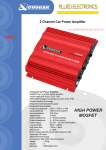
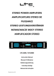
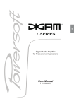
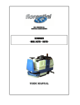
Notice d'utilisation
Amplificateurs
XO5 et XO7
INDEX
1 -- Instructions de sécurité
6 -- Connections d’entrée du signal
2 -- Caractéristiques
7 -- Connections de sortie du signal
3 -- Précautions
8 -- Fonctionnement
4 -- Face Avant
9 -- Entretien
5 -- Face Arrière
10 -- En cas de problème
11 -- Spécifications techniques
1. Instructions de sécurité
1) Attention aux risques de chocs électriques, ne pas ouvrir l'appareil. Il
ne contient aucune pièce nécessitant un entretien.
2) Afin de prévenir tout risque de feu, chocs électriques ou mauvais
fonctionnement, n'exposez pas cette unité à la pluie ou à l'humidité,
n'introduisez pas d'objet métallique et ne renversez pas de liquide à
l'intérieur.
3) N'obstruez pas les entrées et sorties de ventilation cela risquerait
d'entrainer une surchauffe, placez toujours cette unité dans un endroit
bien ventilé, n'installez pas cette unité à proximité d'une source de
chaleur ou une source d'humidité.
4) En cas de problème ne tentez pas de réparer cette unité, confiez là à
un revendeur agréé par la marque.
2. Caractéristiques
La série A de Hortus Audio est une gamme d'amplificateurs
professionnelle, elle est spécialement étudiée pour un usage intensif
permettant d'avoir suffisamment de puissance et une qualité acoustique
satisfaisante.
Les amplificateurs de cette série sont équipés de :
- limiteur automatique
- système de protection contre les courts circuits
- protection contre les défauts d'alimentation
- protection contre la surchauffe
- protection générale
Ils peuvent être branchés en parallèle, stéréo ou en bridge.
Les entrées se font par prises Combo et XLR pour relier plusieurs
amplificateurs.
Les sorties se font par connecteurs Speakon.
Ils sont équipés d'indicateurs de mise en marche, de signal et de
protection.
Ver :-
1
3. Précautions
1) Avant tout branchement de l'unité assurez vous que celle ci est sur
OFF
2) Assurez-vous que le voltage de l'unité correspond à celui de votre
pays
3) Assurez que l'alimentation est adaptée et n'allumez pas tous vos
amplificateurs en même temps
4) Assurez vous que tous les connecteurs sont branchés au bon endroit
et qu'ils sont tous en parfait état
5) Avant toute mise en route, assurez-vous que le sélectionneur de
mode est en bonne position (stéréo, bridge ou parallèle)
6) Vérifiez que les volumes sont au minimum (à gauche) avant toute
mise en route
4. Face Avant
1) Protect (LED ROUGE)
Ces LED indiquent que votre unité est en protection
Elle peut s'allumer pour 3 raisons :
–
–
–
Vos enceintes ne sont pas raccordées à l'amplificateur
La température à l'intérieur de l'unité est trop élevée
Il y a un défaut électrique à l'intérieur de l'unité
2) Limit LED (LED ROUGE)
Quand le signal d'entrée est trop élevé, la LED s'éclaire
3) Signal (LED VERTE)
Quand le signal est présent la LED s'éclaire
Ver :-
2
4) Power (LED VERTE)
Cette LED signifie que l'unité est sous tension
5) CH A / CH B contrôle du niveau de volume
Permet de contrôler le niveau du canal A ou du canal B si vous êtes en
mode Bridge seul CH A fonctionne
6) Interrupteur
Cet interrupteur permet de mettre l'unité sous tension, après quelques
secondes votre amplificateur est prêt à fonctionner.
5. Face Arrière
1) Entrée Combo CH A (CHANNEL A) et CH B (CHANNEL B)
Prises Combo permettant d'entrer le signal soit par JACK soit par XLR
2) Entrée XLR CH A et CH B
Prises XLR permettant de relier l'unité à d'autres unités (pontage de
signal)
3) Sélecteur de mode
Ce sélecteur permet de passer du mode Stéréo au mode Bridge ou
parallèle, en mode bridge ou parallèle seule l'entrée CH A est prise en
compte
4) Sélecteur de sensibilité
Ce sélecteur permet de choisir la sensibilité d'entrée (par défaut 0,775
V) de 0,775V, 1 V ou 1,44 V
Ver :-
3
5) Sortie Speakon
Utilisez des connecteurs standard Speakon 1+, 1-, 2+, 26) Sortie Speakon pour mode BRIDGE uniquement
7) Entrée d'alimentation électrique
8) Fusible de protection
Pour amplificateur A1 fusible : 7A T 125/250 V
Pour amplificateur A2 fusible : 11A T 125/250 V
9) Sélecteur de masse (ground)
Ce sélecteur permet, en cas de bruit résiduel, de changer de mode de
masse"
6. Connections d'entrée du signal
1) Entrées asymétriques
le connecteur est un Jack 6,35 mm MONO
le schéma indique le branchement
2) Entrées symétriques
le connecteur est un XLR mâle
Pin 1 = la masse
Pin 2 = Signal +
Pin 3 = Signal -
Ver :-
4
3) Link de plusieurs amplificateurs
le connecteur est un XLR femelle
7. Connections de Sortie du signal
1) En mode stéréo
branchement de votre speakon
1+, 2+ au + de votre enceinte 1-, 2- au – de votre enceinte
Ver :-
5
2) en mode Bridge
le branchement du spreakon est identique
3) en mode Parallèle
le signal d'entrée se fait uniquement sur le canal A le signal de
sortie se fait sur A et B
8. Fonctionnement
1) Général
a.) Branchez les enceintes correspondantes
b.) S'assurer que les connexions entrée et sortie sont correctes et
branchées correctement
c.) Vérifiez que le voltage correspond
d.) Branchez l'appareil de signal, comme la table de mixage, sur
l'entrée
e.) Réglez le volume au minimum
f.) Activez le bouton du mode choisi (stéréo, bridge ou parallèle)
g.) Activez l'appareil de signal, puis l'amplificateur
h.) Ajustez le niveau d'entrée sur l'intensité voulue.
Ver :-
6
2) Fonctionnement du mode Stéréo, Bridge et Parallèle
A) Mode stéréo
a.) Eteignez l'amplificateur
b.) Branchez les enceintes sur les entrées CHA et CHB
c.) Enclenchez le mode "stéréo"
d.) Signal d'entrée CHA et CHB
e.) Allumez l'amplificateur
f.) Réglez le volume du signal CHA et CHB
Attention : l'amplificateur se mettra en protection en utilisation continue sous 2 Ohms
B) Mode Bridge
a.) Eteignez l'amplificateur
b.) Branchez les enceintes sur les sorties "bridge"
c.) Enclenchez le mode "bridge"
d.) Signal d'entrée CHA
e.) Allumez l'amplificateur
f.) Réglez le volume du signal CHA
Attention: l'amplificateur se mettra en protection en utilisation continue sous 4 Ohms
C) Mode Parallèle
a) Eteignez l'amplificateur
b) Enclenchez le mode "Parallèle"
c) Signal d'entrée CHA
d) Signal de sortie CHA et CHB (branchement aux 2 enceintes)
e) Allumez l'amplificateur
f) Ajustez les gains CHA et CHB
Attention : l'amplificateur se mettra en protection en utilisation continue sous 2 Ohms
9. Entretien
1) Nettoyez régulièrement votre unité avec un chiffon sec et doux,
n'utilisez jamais, de liquide détergent ou d'alcool.
2) Soufflez régulièrement la ventilation afin de dégager les aérations et
ainsi maintenir les capacités de ventilation de l'unité.
Ver :-
7
10. En cas de problème
En cas de problème pensez à vérifier les quelques points suivants :
L'unité ne
s'allume pas Cause possible
:
Il n'y a pas
de son :
Dépannage suggéré
1. l'inter n'est pas sur ON
1. mettez l'inter sur ON
2. le câble d'alimentation
est mal connecté
2. rebranchez le câble
d'alimentation mal connecté
3. le fusible est HS
3. changez le fusible
1. il n'y a pas de signal
d'entrée
1. mettez la source de signal
sous tension vérifiez votre
câblage
2. l'ampli fonctionne mais 2. vérifiez vos connections et
Le niveau de pas les enceintes
cables vérifiez vos enceintes
sortie est
inadapté :
3. problème de
3. vérifiez l'ensemble de vos
connections
connections
4. éteignez l'amplificateur afin
4. la protection thermique
qu'il refroidisse, vérifiez les
est activée
ventilations
Le niveau de
sortie est
inadapté :
Ver :-
1. problème du signal
d'entrée
1. ajustez le volume de
source
2. le voltage de la source
est inadapté
2. utilisez le sélecteur de
tension d'entrée
8
11.
.Spécifications techniques
Modèle
puissance de
sortie :
1 KHz
THD+N < 0,1%
A1
A2
Stéréo 8 Ω
2X500W
2X800W
Stéréo 4 Ω
2X750W
2X1200W
Stéréo 2 Ω
2X900W
2X1440W
Bridge 8Ω
1500W
2400W
Bridge 4Ω
1800W
2800W
Parrallèle 8Ω
2X500W
2X800W
Parrallèle 4Ω
2X750W
2X1200W
Parrallèle 2Ω
2X900W
2X1440W
Important : Les amplis Hortus Audio A1 et A2 disposent d'un système Protect qui peut se
mettre en route lors d'une utilisation sous 2 ohms pendant une trop longue période au
niveau de puissance maximale
Fréquence de réponse
20Hz~20KHz, 1KHz, +0.5dB, -1.0dB
Sensibilité d'entrée
0.775V/1.0V/ 1.44V
S/N Ratio
>100dB
Crosstalk 8 ohms à 1 Khz
>70dB
Protection
Thermique, électrique, court-circuit limiteur automatique
Indicateurs
PROTECT, LIMIT, SIGNAL, POWER
Connections
entrée : 2 COMBO + 2 XLR pour link
Sortie : 3 SPEAKON
Système de refroidissement
ventilation à vitesse variable
Alimentation électrique
AC 230V~50Hz
Dimensions (L x P x H)
483 x 425 x 88 mm
483 x 452 x 88 mm
Poids (NET)
20.0KG
26.5 KG
Amplificateurs Professionnels
Les données imprimées dans ce mode d'emploi sont
susceptibles d'être modifiées sans préavis.
Ver :-
9
USER MANUAL
Professional Power Amplifiers A1 & A2
INDEX
1- Safety instructions
6- Connection (signal input)
2- Main features
7- Connection (signal output)
3- Precaution
8- General Operation
4- Front panel
9- Maintenance
5- Rear panel
10- Troubleshooting
11- Specification
Ver :-
10
1.
Safefy Instructions
1)
2)
3)
4)
2.
Caution: Avoid the risk of electric shock, do not remove the cover. No user
serviceable parts inside.
To prevent fire or shock hazard, do not expose the unit to rain or moisture.
Do not place metal objects or spill liquid inside the unit; electric shock or
malfunction may result.
Don't cover any ventilation slots as this may result in overheating. Always
install the unit in a well ventilated place. Avoid presence of heat source,
and avoid places which are dusty and humid.
Do not repair the unit by yourself. Check or repair the unit by qualified
personnel only.
Main features
A Series Professional amplifiers come with enough power reserve, enabling it to
have good sound performance.
The amplifiers feature:
- Automatic current limiter
- Short circuit protection
- DC fault protection
- High temperature protection
- Overloaded protection
The amplifiers can be connected in 3 modes: parallel, stereo or bridge.
Input connectors: Combo and XLR male connectors for daisy chain linkage
Output connectors: Speakon
Power, Protect, Limit & Signal Indicators.
Ver :-
11
3.
Precaution
1)
2)
3)
Make sure the mains power of the unit is turned off before installation.
Make sure the mains supply matches to the unit's rated voltage.
Use an adequate power source, do not turn on several amplifiers at the same
time.
Make sure all the connectors are well connected in their indicated position
firmly.
Before turning on the power, please check carefully if the mode switch is in its
correct position– stereo, bridge or parallel.
Set the input volume controls to the left ( minimum) before you turn on the
power.
In case the amplifier cannot work properly, stop use it immediately. Do not fix it
by yourself, contact your dealer for service.
4)
5)
6)
7)
4.
Front panel
1) PRO (Protect LED – Red)
The Led will be on under the following three conditions:
1-1/ During first seconds after switching on/ switching off the amplifier. The
protection Led is on when the speakers are disconnected from the amplifier.
1-2/ When the temperature of the power stage becomes too high.
1-3/ In case of a technical defect: DC protection.
2) Limit LED (red)
When the input signal voltage is too high, the LED lights.
3) SGL (Signal LED – green)
When the signal is present, the LED lights.
4) Power LED (green)
When the amplifier is working, the LED lights.
Ver :-
12
5) CHA / CHB input level control
These potentiometers are used to control the input volume of the amplifier. In
bridge mode, only CHA is active.
6) Power switch
This switch sets the power on. After a few seconds, the amplifier is ready to work.
5. Rear panel
1) CHA (Channel A) & CHB (Channel B) Input COMBO connectors
Using a standard XLR and 6.35 (1/4") JACK
2) CHA & CHB Input XLR (male)
XLR input for connecting another amplifier in daisy chain.
3) Mode selector
You can select between Stereo, Bridge or Parallel mode. In Bridge or Parallel
Mode, the input signal must be applied to CH A only.
4) Input sensitivity selector
For 0.775V, 1.00V or 1.44V selection
5) Output Speakon
Using a standard Speakon connector 1+, 16) Speakon output for bridge mode
7) Mains power input
8) Fuse circuit breaker
A1: 7A T 125/250V
A2: 11 A T 125/250V
Ver :-
13
9) Ground / Lift Switch
This switch allows to change the Ground / Lift position in case of nasty hum noises.
6. Connections (Signal Input)
1) Unbalanced Input (Combo connector)
Input 6.35 mm (1/4") phone JACK:
The diagram below indicates the connection
Photo (1)
2) Balanced Input (Combo connector)
Input female XLR
Pin 1 = Ground
Pin 2 = Signal +
Pin 3 = Signal-
Photo (2)
3) CHA & CHB Link
Input male XLR for linking to another amplifier
Photo (3)
Ver :-
14
7. Connections (Signal Output)
1) Stereo Mode
CHA & CHB stereo output connection:
1+ Signal output (+)
1- Signal output (-)
connect to speaker (+)
connect to speaker (-)
Photo (4)
2) Bridge
Signal input only on CH A
Signal output only on bridge output
Volume control is done with the volume switch A
Photo (5)
3) Parallel Mode
The input signal is from CHA only, the output signal is from CHA and CHB.
Photo (6)
Ver :-
15
8. General Operation
1) General Operation:
a.)
b.)
c.)
d.)
e.)
f.)
g.)
h.)
Connect to the matching speakers
Make sure all the input & output connections are correct and well connected
Make sure the mains power matches the units rated voltage
Connect ht signal source equipment, like Mixer, to the amplifier's signal input
Set amplifier's input level to the minimum
Set the mode switch to the mode (stereo, bridge, or parallel) required
Turn on the power of signal source equipment, then the amoplifier
Then adjust the input level to the intensity required.
2) Operation procedure of Stereo, Bridge & Parallel Mode:
A.) Stereo Mode:
a.)
b.)
c.)
d.)
e.)
f.)
Turn off the power of the amplifier
Speakers connect to CHA and CHB outputs
Set mode switch to "stereo" mode
Input signal from CHA and CHB
Turn on the power of amplifier
Adjust CHA and CHB signal volume
If used continuously at its maximum power under 2 Ohms, the amplifier will put itself into
protection.
B.) Bridge Mode:
a.)
b.)
c.)
d.)
e.)
f.)
Turn off the power of the amplifier
Speaker connect to the "bridge" speakon output
Set mode switch to "bridge" mode
Input signal from CHA
Turn on the power of the amplifier
Adjust CHA signal volume
If used continuously at its maximum power under 4 Ohms, the amplifier will put itself into
protection.
C.) Parallel Mode:
a.)
b.)
c.)
d.)
e.)
f.)
Turn off the power of the amplifier
Set mode switch to "parallel" mode
Input signal from CHA
Output signal from CHA and CHB (connect to 2 speakers)
Turn on the power of the amplifier
Adjust CHA and CHB gain controls respectively for the output volume of CHA and
CHB
If used continuously at its maximum power under 2 Ohms, the amplifier will put itself into
protection.
Ver :-
16
9. Maintenance
1) Clean the unit by wiping with a slightly damp cloth. Avoid getting water inside
the unit. Do not use alcohol or any volatile liquid that will damage the unit.
2) Clean the ventilation slots regularly with a vacuum cleaner. This increases the
cooling capacity of the amplifier fans and help preventing temperature
overheat.
10. Troubleshooting
You can check some operation problems as mentioned below first before asking for
help.
Problem
No response
when power on
Problem cause (s)
Suggested Remedy
1、 Power did not turn on
1、 Turn on the power.
2、 Lost connection of the power
cord
2、 Make sure the power cord is
connected firmly to the mains
supply before turn on the power of
amplifier.
3、 Blown fuse
3、 Replace the fuse with same type
only if the fuse is blown.
1、 No signal input
1、 Connect
the
signal
source
equipment to the amplifier, then
turn on the power.
2、 Connection of the speaker
lost or damaged speaker
2、 Make sure the speaker is well
connected. Check if the speaker is
in good condition.
3、 Wrong connection
3、 Make
sure
the
connection
between amplifier and speaker is
correct. Please refer to the point 7
Connection (signal output) for
more information.
4、 Thermal protection
4、 Avoid overloading the amplifier for
a long time, or working in a bad
ventilation area. Check if the fans
work properly or the ventilation
slots is clear of dust:
1、The signal input level
(intensity) is set at minimum
1、Adjust the signal input level to the
appropriate intensity
2、Low input voltage of the
signal source equipment (CD
Player)
2、Increase the input voltage of the
signal source equipment Adjust
the input sensitivity of the
amplifier
No sound
Inadequate
output volume
Ver :-
17
11.
.Specification
Model
A1
A2
Stereo 8Ω
2X500W
2X800W
Stereo 4Ω
2X750W
2X1200W
Stereo 2Ω
2X900W
2X1440W
Bridge 8Ω
1500W
2400W
Bridge 4Ω
1800W
2800W
Parallel 8Ω
2X500W
2X800W
Parallel 4Ω
2X750W
2X1200W
Parallel 2Ω
2X900W
2X1440W
Output Power :
1 KHZ
THD+N < 0,1%
Important: Hortus amplifiers feature a Protect system which will activate when the amplifier is
used under 2 Ohms at its maximum power during long periods of time.
Frequency Response
20Hz~20KHz, 1KHz, +0.5dB, -1.0dB
Input Sensitivity
0.775V/1.0V/ 1.44V
S/N Ratio
>100dB
Crosstalk at rated output
8Ohms1KHz
>70dB
Protection
Short circuit, DC fault, AC line fuse, thermal cut off,
soft start, automatic current limiter
Indicators
PROTECT, LIMIT, SIGNAL, POWER
Connector
Input: 2 COMBO + 2 XLR link male
Output : 3 SPEAKON
Cooling System
Variable speed fan
Power Supply
AC 230V~50Hz
Dimensions (L x P x H)
483 x 425 x 88 mm
483 x 452 x 88 mm
Weight (NET)
20.0KG
26.5 KG
A Series Professional Power Amplifiers
Specification is subject to change without prior notice.
Ver :-
18