1
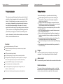
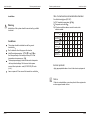
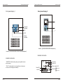
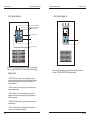
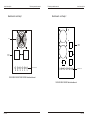
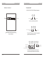
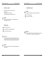
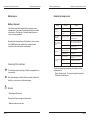
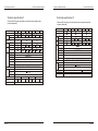
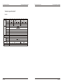
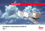
Catalog
Product introduction--------------------------CH-1
features------------------------- ----------------CH-1
Product user manual
safefy attention------------------------------- CH-2
install description---------------------------- CH-5
enviroment
CH-5
biggest current and recommended connected wire
CH-6
outside protective equipment
CH-6
front panel display 1
CH-7
front panel display 2
CH-8
front panel display 3
CH-9
front panel display 4
CH-10
front panel display 5
CH-11
front panel display 6
CH-12
Backboard and help 1
CH-13
Backboard and help 2
CH-14
Backboard and help 3
CH-15
connection terminal 1
CH-16
connection terminal 2
CH-17
outside connected battery operation instruction
CH-18
Equipment renning operation---------------CH-19
primary running control
CH-19
starting
CH-19
shut down
CH-20
maintainence/simple failure process-------CH-21
maintainence of the machine
CH-21
simple failure process
CH-22
Technical specification-- -- -------------------CH-23
Inverter Power
Technical specification 1
CH-23
Technical specification 2
CH-24
Technical specification 3
CH-25
Product introduction
Product operation manual
Product introduction
Product operation manual
Safety attention
Safety attention:
To ensure the safety use, pls. adhere to the following:
This series is specially designed for the area which is lack of
electricity, it is an intergration of in inverter,controller, VRLA
battery. It is digital design, pure sine-wave output, low-freq
uency design, independent modularization which enhances
the reliability andexpandability of the product. It is mainly
applied to the solar energy PV generating system, wind power
system, wind, sun, oil,storage hybrid generating system and
provide AC power supply for remote area, satellite groud re
ception, observatory, frontier defence station,communication
station, electroless island and so on.
Features:
Advanced performance by CPU control.
Suitable packing method is required when making the
transportation of the goods.( To keep the equipment
steady or non-vibrative.)
It might be water when the machine was moved from low
temperature environment to high temperature environment.
Dry the machine before use to ensure safety.
Read through the user manual particularly before use.Don't
exceed rated load.
Cut off the power immediately in case the failure occurred
and contact with the dealer.
Pls. use dry fire extinguisher and liquid fire extinguisher in
case fire caused from the surrounding environment of the
machine.
In order not to pour it into the machine, pls. don't place the
container with liquid on the top of the equipment
The risk of causing short circuit or electric shock or catching
fire.
The equipment should be connected to the ground well to
ensure the safety.
Adopt low frequency transformer, pure sine wave output, adapt
to different load.
Danger
IGBT module with high reliability.
All the load should be disconnected before connecting the
equipment. It is not allowed to put out the fire with water.
High effciency energy-saving and environmental protection.
Intelligent battery management, protection against over-charged
and over-discharged to prolong the service life of the battery.
drain current
Connect well the ground line before the connection of the cables.
Concise LED/LCD display to check the working status.
Full-oriented protection with high reliability.
Invert/charge/battery intergration,simple configuration,costeffective, suitable for users.
Can be used at wide range of temperatures and high altitude
CH-1
Radio disturbance
This series is A class radio disturbance product, do not let the
equipment which is sensitive to the equipment(such as emitter,
receiver, radar, metal locator to get close to the equipment.
CH-2
Safety attention
Product operation manual
Battery
Please go to the specialist for maintenance of the batteries
Keep the batteries in a dry environment. Electrolyte leakage
may happen when it is broken, which is harm to the eyes
and skin. In case of the electrolyte in the eyes or on the
skin, rinse with water and go to the doctor.
When the batteries are in series, the voltage of the battery
bank may be dangerous for human. Don't touch the battery
bank.
When the battery is short circuit or discharged with large
current, it will probably be broken or even catch on fires.
If the battery is SLA one, recharge it after 6 months storage
( on 20 ). Or battery failure may occur. Charge the battery
every four months is advisable.
New battery can not be 100% charged after the first charge.
It will takes several charge and discharge circles
Dispose the battery scrap properly and deliver it to the
battery recycle organization.
Product operation manual
Safety attention
Transportation and storage
Transportation
Check the packing of the goods. If it is broken or there is some
part of the system missing, please notify the dealer within 7
days.
Unpack
Be careful, when unpacking. Check the packing if it is good.
Storage
Please put the goods in a clean, dry environment. And the
temperature should be between( 0 -35 )
Move
Keep the packing on the up side and move it careful. Any falloff
or strike may break the machines.
CH-3
CH-4
Install description
Product operation manual
Installation
Product operation manual
Install description
Max. Current and recommended cable diameter
See the following figure( IEC-287)
Warning
Installation of this system should be carried out by qualified
technicist
1
2
3
PVC-insulated copper wire (@70 )
Temperature: below 40
If the two conditions above can not be met, wider
cable is needed.
Rated power W
Conditions
This system should be installed on shelf or ground
horizontally.
Don't stack with other things upon the inverter
Ideal Running temperature: 15 -25 . From 20 on,
the life expectancy of the battery will drop 50% if the
temperature increases every 10
These equipments apply to wind turbine and solar panels
with equivalent wattage. Don't connect other power
source to the input ends---wind (W1/W2/W3) OR solar
(s+/s-).
Leave a space of 2.5cm around the inverter for ventilation
150 300
(12V) (24V)
500
750
1000
1500
2000
3000
Input cable diameter
of wind turbine(
)
2
3
3
4
4
4
6
6
Input cable diameter
of PV panels
1.5
1.5
2
3
3
3
3
4
Output cable
diameter ( )
2
3
3
4
6
4
6
8
Ground line
diameter (
)
0.5
0.5
0.75
0.75
1
1.5
2
2.5
Battery wire
diameter (mm 2)
0.5
0.5
0.75
0.75
1
1.5
2
2.5
Exterior protector
Apply appropriate breaker or fuse to the exterior equipments
Notice
If there is external battery case, keep it next to the equipments
and use proper breaker or fuse.
CH-5
CH-6
Install description
Product operation manual
Front panel display 1
Product operation manual
Install description
Front panel display 2
LCD
Sine-Wave
Inversion
indicator
ON
On
Off
OFF
Failure
indicator
Inverter
1500W/2000W/3000W Model panel
Inverter (150W/300W/500W/750W/1000W Model panel)
Indicator instruction
Indicator instruction
Output LED
Battery LED
"INVERTER" Indicator light is green, green signifies inverter
normal running.
"FAULT" Indicator light is red, red signifies over load power
or short circuit/ running down of battery.
Battery capaclty LED
Output LED
Load LED
CH-7
Normal LED
State LED
Alarm LED
CH-8
Install description
Product operation manual
Front panel display 3
Product operation manual
Install description
Front panel display 4
Wind turbine indicator light
WIND
SOLAR
BATTERY
Solar energy indicator light
Battery indicator light
Invert indicator light
On
Sine-Wave
On
Off
Off
Fault indicator light
Conversion& Charge by wind and solar power incorporated
System 150W/300W/500W/750W/1000W model panel
display help
Conversion& Charge by wind and solar power incorporated
System 1500W/2000W/3000W model panel
"BATTERY" Indicator light is bi-colour light(green/yellow).
Green signifies battery normal voltage, yellow signifies battery
under voltage, green/yellow twinkle signifies battery over
charge protection
"SOLAR" Indicator light is green light. Green signifies solar
energy normal running.
"WIND" Indicator is bi-colour light(green/yellow). Green
signifies wind turbine normal running. Yellow signifies wind
turbine is unloaded.
"INVERTER" Indicator light is green, green signifies inverter
normal running.
"FAULT" Indicator light is red, red signifies over load power
or short circuit/ running down of battery.
CH-9
CH-10
Install description
Product operation manual
Front panel display 5
Product operation manual
Install description
Front panel display 6
Wind turbine indicatior light
Solar energy indicatior light
Battey indicator light
Output current
Battery indicator light
Inver indicator light
Output voltage
Invert indicator light
Wind turbine indicator light
Solar energy indicator light
On
OUTPUT VOLTAGE
OUTPUT CURRENT BATTERY VOLTAGE
On
Battery voltage
Off
Off
Fault indicator light
Fault indicator light
Conversion& Charge by wind and solar power incorporated system
(internal batteries) (1500W/2000W/3000W Model panel
CH-11
Conversion& Charge by wind and solar power incorporated system
(internal batteries) (1500W/2000W/3000W Model panel
display help
display help
"BATTERY" Indicator light is bi-colour light(green/yellow).
Green signifies battery normal voltage, yellow signifies battery
under voltage, green/yellow twinkle signifies battery over
charge protection
"BATTERY" Indicator light is bi-colour light(green/yellow).
Green signifies battery normal voltage, yellow signifies battery
under voltage, green/yellow twinkle signifies battery over
charge protection
"SOLAR" Indicator light is green light. Green signifies solar
energy normal running.
"SOLAR" Indicator light is green light. Green signifies solar
energy normal running.
"WIND" Indicator is bi-colour light(green/yellow). Green
signifies wind turbine normal running. Yellow signifies wind
turbine is unloaded.
"WIND" Indicator is bi-colour light(green/yellow). Green
signifies wind turbine normal running. Yellow signifies wind
turbine is unloaded.
"INVERTER" Indicator light is green, green signifies inverter
normal running.
"INVERTER" Indicator light is green, green signifies inverter
normal running.
"FAULT" Indicator light is red, red signifies over load power
or short circuit/ running down of battery.
"FAULT" Indicator light is red, red signifies over load power
or short circuit/ running down of battery.
CH-12
Product operation manual
Install description
Backboard and help1
Product operation manual
Install description
Backboard and help 2
Fan
Output
socket
OUTPUT
Output
socket
OUTPUT
OUTPUT
Connector bar
W1
W2
W3
S+
B-
B+
Connector bar
W1
W2
W3
SS+
B-
B+
R1
R2
R3
150W/300W/500W/750W/1000W Model backboard
1500W/2000W/3000W Model backboard
CH-13
CH-14
Product operation manual
Install description
Backboard and help 3
Product operation manual
Install description
Connector bar 1
(150W/300W/500W/750W/1000W Model backboard )
B-
Output
socket
Terminal board
BAT+
BAT-
W1
W2
W3
S+
S-
L
B+
Pile negative
Pile positive
N
Inverter backboard teminal board
S+
B-
B+
Solar energy pile positive input
Pile positive
Pile negative
1500W/2000W/3000W Model backboard
(internal batteries)
Conversion& Charge by solar power incorporated
system backboard teminal board
W1
W2
W3
S+
B-
B+
Aerogenerator input
Pile positive
Aerogenerator input
Pile negative
Aerogenerator input
Solar energy pile positive input
Conversion& Charge by wind and solar power
incorporated system backboard teminal board
CH-15
CH-16
Product operation manual
Install description
Connector bar 2
Product operation manual
Instruction of battery connection
Connect the batteries with the same capacity in series,
according to the system voltage. And you can connect the
battery bank in parallel as well.
There should be a DC switch between the inverter and
battery bank. The rated current of the switch should be
larger than the ones in the following chart:
(1500W/2000W/3000W Model backboard )
B+
B-
Pile positive
Pile negative
Rated power W
Inverter backboard teminal board
S+
Pile negative
Conversion& Charge by solar power incorporated
system backboard teminal board
R2
R3
R1
Aerogenerator input
W3
S+
B-
B+
R1
R2
12
24
24
24
24
48
48
48
MAX. current of the
battery back
16
16
26
40
55
40
55
80
When the battery connection is normal and after the air switch
is on 1-2 seconds later, you will hear the ON sound of the
relay from the inverter.
R3
Aerogenerator input
Unloaded resistance 3
Unloaded resistance 2
Aerogenerator input
Unloaded resistance 1
Solar energy pile positive input
Pile positive
Voltage of battery
bank
Notice
R1 R2 R3
W2
150W 300W
500W 750W 1000W 1500W 2000W 3000W
(12V) (24V)
The air switch of the battery bank is off. Then connect the
batteries in series. Check the voltage of the battery bank
with multimeter.
Positive terminal: red wire; Negative terminal: black wire.
Then connect the red wire to B+ and black wire to
on the back panel of the inverter.
Turn on the switch.
B+
B-
Solar energy pile positive input
Pile positive
W1
Install description
Pile negative
Solar energy pile
negative input
1500W/2000W/3000W Instruction for wind turbine uninstall
According to the power of the wind turbine and the requirement
of user, choose the right resistance of uninstall:
Rated input power of
wind power
Conversion& Charge by wind and solar power
incorporated system backboard teminal board
CH-17
Resistance of uninstal
1000W
7
/500W
1500W
2000W
4.5 /600W
3.5 /1000W
CH-18
Product operation manual
Equipment running operation
Initial run control
Before start up the inverter, please check:
Ventilation
Connection of the ground line
All the switches are in the position of ¡°
OFF¡±
.
Product operation manual
Equipment running operation
Turn off the inverter
Notice
Doing this will cutoff the power supply of all the loads
Turn off the loads and
Press on the OFF switch
Notice
Do the same as the instruction ,or something may occur
during the power supply.
Startup step
Press the
on
switch
5 seconds till the output voltage is stable
Turn on the loads one by one.
Notice
After pressing the "off" button on the front panel, you stop the
conversion only. The charge controller still works on.
Dangers
If the inverter is overloaded, there will be warning sound con
tinuously. Please turn off some loads. Start the inverter again.
The air switch of the external battery case should be on .
Notice
If the inverter is not loaded, it will turn off automatically 4-5
minutes later.
CH-19
CH-20
Maintainence/simple failure process
Product operation manual
Maintenance
Battery disposal
The batteries should be replaced by the customer service
representative. The scrap of the lead acid battery is classified
as toxic waste. The disposal of it should abide by laws and
rules of recycle department.
Solution for simple error
Failure
¡°
BATTERY¡±
indicator is off
Battery indicator
( yellow) is on
Normally, the life expectancy of the battery is 3 years, when
it is 25 . But still we should take the running time and
frequency of the inverter into consideration.
Maintainence/simple failure process
Product operation manual
¡°
FAULT¡±
indicator
is on and continuous
beeping
Reasons
Solution
The connection of batteries
is wrong
Double check the connection of the
batteries
Errors on the charge
controller.
Tell the customer service
representative.
Low voltage of the battery
bank.
Unplug all the loads to protect the
batteries. When the voltage is normal,
the indictor will be off
Short circuit on the output
end.
Turn off the inverter and unplug all the
loads. Then check the loads to see if
there are malfunctions in the loads.
Overload
Check the loads and unplug the
unimportant loads.
The connection between the battery
Check the connection.
bank and inverter is not right.
Startup error
Internal fuse is broken;
Internal malfunction
Tell the customer service
representative.
Battery undercharge
Make sure to charge the batteries
over 8 hours.
The on load discharge
Over load
time is less.
Cleansing of the machines
Turn off the inverter accordingly. Clean the casing with dry or
tiny wet cloth.
Battery is aging
Unplug the unimportant loads.
Replace the batteries
Provide the following information to the customer service
representative:
¡îModel Serial number The date you bought the products.
¡îDetails of the malfunctions.
After the cleansing, check the all the connections. When it is
totally dry, you can turn on the inverter again.
Notices
ØNo detergent. Water only.
Prevent liquid from running into the machine.
ØMake sure the airway is clear
CH-21
CH-22
Product operation manual
Technical specification
Technical specification 2
Technical specification 1
Conversion& Charge by wind and solar power incorporated system
( internal batteries)
Conversion& Charge by wind and solar power incorporated system
( external batteries)
Rated Power(W)
Rated power (W)
300
150
500
750
1000
1500
3000
2000
Rated dc voltage(VDC)
Battery capacity
(12V,65AH) (12V,100AH) (12V,100AH) (12V,100AH) (12V,65AH) (12V,100AH) (12V,65AH) (12V,100AH)
8
8
1
1
2
2
4
4
Back up time (H)
3-4
Battery
Battery over discharge
alarm voltage VDC
DC voltage range
Solar
(VDC)
energy
Max. Power (Wp)
input
Wind
turbine
input
CH-23
<3%
130%,1 minute shutdown
Other
Soft start protection for battery input reverse connection, battery voltage-lack/over-voltage,
output overload/short circuit, overheat etc.
1500VAC,1 minute shutdown
10
0-90%
480
12/15
235
510
15/18
480
18/22
235
770
19/23
~
3:1
Soft start protection for battery input reverse connection, battery voltage-lack/over-voltage,
output overload/short circuit, overheat etc.
1500VAC,1 minute shutdown
Insulating strength
Invert efficiency
(80% impedance load)
environmental
temperature
environmental
humidity
3000
2000
Input rated
voltage(V)
Protection function
3:1
Insulating strength
1500
Invert efficiency
(80% impedance load)
130%,1 minute shutdown
Peak factor
1000
Max. Power(Wp)
Peak factor
<3%
Overload capacity
Remark
750
Overload capacity
Output frequency
range
AC output distortion rate of a
wave(linearity load)
NW/GW (Kg)
(not including the battery)
500
Output voltage
range
Output frequency
range
AC output
distortion rate of a
wave(linearity load)
Max. Power (Wp)
Appearance (D W H)(mm)
300
Battery over discharge
alarm voltage VDC
DC voltage range
Solar
(VDC)
energy
input
Max. Power(Wp)
Output voltage range
Other
150
Rated DC voltage(VDC)
Wind
turbine
input
Input rated voltage
(V)
Protection function
Technical specification
Product operation manual
environmental
temperature
environmental
humidity
Appearance (D W H)(mm)
55
NW/GW (Kg)
uncondensed
Remark
480
21/26
460
10
0-90%
950
32/38
880
40/46
460
400
10/11
11/12
145
12/13
~
55
uncondensed
450
210
12.5/15
13.7/16.2
23/25.5
190
27/29.5
330
39/41.5
Specification only for reference. Subject to change without prior notice.
950
55/61
Specification only for reference. Subject to change without prior notice
CH-24
Product operation manual
Technical specification
Technical specification
Product operation manual
Technical specification 3
Inverter
Rated power (W)
150
Input Rated voltage
(VDC)
Input Rated current
(A)
DC input
DC voltage range
(VDC)
16
Battery over discharge
alarm voltage(VDC)
AC output
300
500
32
30
1500
45
60
40
60
90
11
22
44
<3%
130%,1 minute shutdown
Peak factor
3:1
82%
Soft start protection for battery input reverse connection, battery voltage-lack/over-voltage,
output overload/short circuit, overheat etc.
1500VAC,1 minute shutdown
Insulating strength
environmental
temperature
environmental
humidity
20
0-90%
Appearance (D W H)(mm)
Remark
3000
44-60
Invert efficiency
(80% impedance load)
NW/GW (Kg)
2000
22-30
Output voltage
range
Output frequency
range
distortion rate of a
wave(linearity load)
Protection function
CH-25
1000
11-15
Overload capacity
Othe
750
400
11/12
11/12
145
12/13
~
55
uncondensed
450
210
12.5/15
13.7/14.7
23/25
190
27/29
330
39/41
Specification only for reference. Subject to change without prior notice.
CH-26