1
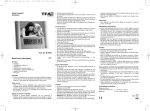
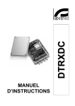
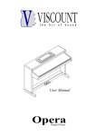
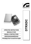
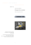
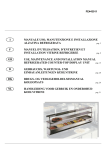
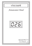
viscount
Pipe 27
Manuale Operativo
Owner's Manual
Mode d ' Emploi
Bedienungsanleitung
WARNING: READ THIS FIRST!
∗∗∗
AVIS IMPORTANT!
WARNING
RISK OF ELECTRIC SHOCK
DO NOT OPEN
AVIS
RISQUE DE CHOC ÉLECTRIQUE
NE PAS OUVRIR
This symbol is intended to alert the user to the
presence of uninsulated “dangerous voltage”
within the product’s enclosure that may be of
sufficient magnitude to constitute a risk of electric
shock to persons.
This symbol is intended to alert the user to the
presence of important operating and maintenance
(servicing) instructions in the literature
accompanying the appliance.
Ce simbole sert pour avertir l’utilisateur
qu’à l’interieur de ce produit sont
présents éléments non isolés soumis à
“tensions dangereuses” suffisants à créer
un risque d’électrocution.
Ce simbole sert pour avertir l’utilisateur
qu’à l’interieur de la documentation de
l’appareil sont présentes importantes
instructions pour l’utilisation correcte et la
manutention de l’appareil.
ATTENTION
CAUTION
TO REDUCE THE DANGER OF ELECTRIC SHOCK
DO NOT REMOVE COVER (OR BACK)
NO USER-SERVICEABLE PARTS INSIDE
REFER SERVICING TO QUALIFIED SERVICE PERSONNEL
AFIN D’EVITER LES RISQUES DE CHOC ÉLECTRIQUE:
NE PAS OUVRIR LE COUVERCLE (OU PANNEAU ARRIERE)
L’UTILISATEUR NE PEUT EFFECTUER AUCUNE REPARATION
PUOR TOUTE REPARATION EVENTUELLE, FAIRE APPEL A
UN PERSONNEL QUALIFIE
“INSTRUCTIONS PERTAINING TO A RISK OF FIRE,
ELECTRIC SHOCK, OR INJURY TO PERSONS”
IMPORTANT SAFETY INSTRUCTIONS
WARNING:
1) Read these instructions.
2) Keep these instructions.
3) Heed all warnings.
4) Follow all instructions.
5) Do not use this apparatus near water.
6) Clean only with dry cloth.
7) Do not block any ventilation openings. Install in accordance with the manufacturer’s instructions.
8) Do not install near any heat sources such as radiators, heat registers, stoves,
or other apparatus (including amplifiers) that produce heat.
9) Do not defeat the safety purpose of the polarized or grounding-type plug. A polarized plug has two blades with one
wider than the other. A grounding type plug has two blades and a third grounding prong. The wider blade or the third
prong are provided for your safety. If the provided plug does not fit in to your outlet, consult an electrician for replacement
of the obsolete outlet.
10) Protect the power cord from being walked on on pinhead, particularly at plugs, convenience receptacles,
and the point where they exit form the apparatus.
11) Only use attachments/accessories specified by the manufacturer.
12) Use only with the cart, stand, tripod, bracket, or table specified by
the manufacturer, or sold, with the apparatus.
When a cart is used, use caution when moving the cart/apparatus
combination to avoid injury from tip-over.
13) Unplug this apparatus during lightning storms or when unused for long periods of time.
14) Refer all servicing to qualified service personnel. Servicing is required when the apparatus has been damaged
in any way, such ad power-supply cord or plug is damaged, liquid has been spilled or objects have fallen into
the apparatus, the apparatus has been exposed to rain or moisture, does not operate normally, or has been dropped.
SAVE THESE INSTRUCTIONS ∗∗∗ INSTRUCTIONS A CONSERVER
viscount Pipe 27
INDICE
1. PANNELLO DI CONTROLLO ................................................................................................... 1
2. PROCEDURA DI ASSEMBLAGGIO......................................................................................... 2
1. PANNELLO DI CONTROLLO
1. Prese INPUT L/M – R: prese Jack a cui collegare i cavi provenienti dalle uscite ANTIPHONAL OUT
presenti sul pannello posteriore del Vostro organo VISCOUNT.
In caso di utilizzo dell’uscita ANTIPHONAL OUT 1(+2) collegate l’ingresso L/M. In caso di utilizzo della coppia
di uscite 1(+2) e 3(+4) utilizzate entrambi i connettori L/M e R.
2. Prese 12V DC: prese per l’alimentazione esterna fornita dai connettori EXT +12V DC siti sul pannello
posteriore del Vostro organo VISCOUNT.
3. Potenziometro LEVEL: tramite questo potenziometro potrete controllare il volume generale dell’amplificatore.
4. Potenziometro BASS TONE: tramite questo potenziometro potrete regolare i toni bassi del suono.
5. LED ON: questo LED visualizza l’accensione dell’amplificatore.
6. Presa MAIN: presa per collegare il cavo per l’alimentazione esterna.
7. Interruttore LOCAL – OFF – REMOTE: interruttore con il quale selezionare la modalità di alimentazione:
LOCAL: l’alimentazione viene fornita dal cavo collegato alla presa MAIN.
OFF: amplificatore spento.
REMOTE: l’alimentazione viene fornita dall’organo collegato tramite le prese 12V DC.
1
viscount Pipe 27
2. PROCEDURA DI ASSEMBLAGGIO
1. Posizionare la base [A] sopra l’organo verificando
che i fianchi dei due mobili coincidano.
2. Avvitare nei fianchi [B] i piedini [H].
2
viscount Pipe 27
3. Fissare i fianchi [B] alla base [A]
inserendo i ciondoli [C] nei fori [D].
4. Svitare dall’organo le viti [E] (1a e 4a
dall’alto) e riavvitarle con gli angolari [F].
Regolare i piedini [H] al fine di ottenere una
perfetta equilibratura dello strumento.
3
viscount Pipe 27
5. Praticare quattro prefori (∅ 3 mm.) nei fianchi
[B] dove verranno avvitate quattro viti 4 x 16 TCFR
([G] nel disegno) al fine di fissare i fianchi [B] con
gli angolari [F].
6. Posizionare il Pipe 27 sopra la base [A]
verificando che lo stesso sia ben centrato con la
base sottostante. Quindi praticare otto prefori [J]
(∅ 3 mm.) in cui verranno avvitate le viti [I] (4 x 40
TS).
4
viscount Pipe 27
CONTENTS
1. CONTROL PANEL ..................................................................................................................... 5
2. ASSEMBLING INSTRUCTIONS ............................................................................................... 6
1. CONTROL PANEL
1. INPUT L/M - R Jack sockets: for the connection to the ANTIPHONAL OUT output sockets located on the
rear panel of the VISCOUNT organ.
To use the ANTIPHONAL OUT 1(+2), please connect to the L/M input.
To use the two outputs 1(+2) and 3(+4) please use both connectors L/M and R.
2. 12V DC sockets: for the external voltage supplied by connectors EXT +12V DC located on the rear panel
of the VISCOUNT organ.
3. LEVEL potentiometer: to control the general volume of the amplifier.
4. BASS TONE potentiometer: to adjust the sound bass tones.
5. LED ON: this shows the status of the amplifier On or Off.
6. MAIN socket: for the connection of the power cable.
7. LOCAL – OFF – REMOTE switch:
- when LOCAL it is powered through the power cable connected to the MAIN socket
- when OFF the amplifier is off
- when REMOTE it is powered by the organ connected through the 12V DC sockets.
5
viscount Pipe 27
2. ASSEMBLING INSTRUCTIONS
1. Set the base [A] on the organ.
2. Fix the rubber feet [H] to the side panels [B].
6
viscount Pipe 27
3. Fix the side panels [B] to the base [A]
inserting the pins [C] in the holes [D].
4. Unscrew from the organ the screws [E]
(1st and 4th from the top) and screw them to
the iron corners [F]. Adjust the rubber feet
[H] for perfect balance.
7
viscount Pipe 27
5. Drill 4 holes (3 mm) in the side panels [B] in
order to screw in 4 screw, 4x 16 TCFR [G] fixing
the side panels [B] with the iron corners [F].
6. Set the Pipe 27 on to the base [A] and check it
is central. Drill 8 holes [J] (∅ 3 mm.) where to
screw in the 4 x 40 TS screw (I).
8
viscount Pipe 27
SOMMAIRE
1. PANNEAU DE CONTRÔLE ...................................................................................................... 9
2. INSTRUCTIONS D’ASSEMBLAGE ....................................................................................... 10
1. PANNEAU DE CONTRÔLE
1. Connecteurs INPUT L/M - R: pour effecteur (à l’aide de cablês appropriés) la connection aux sorties
ANTIPHONAL OUT situées sur le panneau arriére de votre orgue VISCOUNT.
Si vous utilisez une seule sortie ANTIPHONAL OUT 1(+2), connectez vous sur l’entreé repérée L/M.
Si vous utilisez les deux sorties 1(+2) et 3(+4) connectez vous sur les deux entrée repérées L/M et R.
2. Connecteur 12V DC: permet une alimentation externe à partir des connecteurs EXT +12V DC situés sur
le panneau arriére de votre orgue VISCOUNT.
3. Potentiomètre LEVEL: permet de contrôler le volume général de l’amplificateur.
4. Potentiomètre BASS TONE: permet de contrôler le niveau des basses.
5. Indicateur lumineux LED ON: indique l’état sous / hors tension de l’amplificateur.
6. Connecteur MAIN: permet le raccordement du câble d’alimentation.
7. Interrupteur LOCAL – OFF – REMOTE:
- Lorsque cet interrupteur est sur LOCAL, l’alimentation électrique est fournie par le câble relié au
connecteur MAIN.
- Sur OFF l’amplificateur es hors tension.
- Sur REMOTE l’alimentation est fournie par l’orgue grâce au connecteur 12V DC.
9
viscount Pipe 27
2. INSTRUCTIONS D’ASSEMBLAGE
1. Installez la base [A] sur l’orgue.
2. Fixez les panneaux latéraux [B] à travers le joint de
caoutchouc [H].
10
viscount Pipe 27
3. Fixez les panneaux latéraux [B] sur la
base [A] en insérant les chevilles [C] dans
les trous [D].
4. Dévissez sur l’orgue les vis [E] (1ere et
4éme à partir du haut) et re-vissez les après
avoir ajusté les cornières en acier [F]. Ajustez
le joint caoutchouc [H] de manière optimale.
11
viscount Pipe 27
5. Effectuez 4 trous (∅ 3 mm) dans les panneaux
latéraux [B] afin de visser 4 vis de type 4 x 16
TCFR [G] fixez les panneaux latéraux [B] avec les
cornières en acier [F].
6. Installez le Pipe 27 sur la base [A] et vérifiez
qu’il est bien positionné au centre. Percez 8 trous
[J] (∅ 3 mm.) afin de visser les 4 vis de type 4 x
40 TS [I].
12
viscount Pipe 27
INHALTSVERZEICHIS
1. KONTROLLEN ........................................................................................................................ 13
2. HINWEISE ZUM AUFBAU ...................................................................................................... 14
1. KONTROLLEN
1. INPUT L/M Jack Buchsen: fuer die Verbindungkabel, die von der Anschlussplatte auf die Rueckseite
Ihrer VISCOUNT Orgel her kommen. Wenn Sie die ANTIPHONAL OUT 1(+2) benuetzen (1 kanal), verbinden
Sie den L/M Eingang (L/M bedeutet “links mono”). Wenn Sie die zwei Ausgaenge 1(+2) und 3(+4) an der
Orgel benutzen, verbinden Sie diese mit den Buchsen L/M und R.
2. 12V DC Buchse: fuer den Anschluss ueber ein 2-adriges Kabel an die EXT +12V DC Buchse, die sich
auf die Rueckseite Ihrer VISCOUNT Orgel befindet. Damit kann das Pipe-Cabinet von der Orgel her aus-und
eingeschaltet werden.
3. LEVEL Potentiometer: regalt die Gesamtlautstaerke des Pipe-Cabinet.
4. BASS TONE Potentiometer: regelt den Bassnteil des Klanges.
5. LED ON: Betriebsanzeige.
6. MAIN Buchse: der Anschluss fuer das Netzkabel.
7. LOCAL – OFF – REMOTE Schalter:
Stellung:
- LOCAL, Stromversorgung direkt ueber das mitgelieferte Netzkabel.
- OFF, das Pipe-Cabinet ist ausgeschaltet.
- REMOTE, das Pipe-Cainet wird ueber das Kabel zwischen den Buchsen 12V DC jack der Orgel
und dem Pipe-Cabinet von der Orgel geschaltet. Das Netzkabel des Pipe-Cabinet muss eingesteckt
sein!
13
viscount Pipe 27
2. HINWEISE ZUM AUFBAU
1. Setzen Sie den Sockel [A] auf die Orgel.
2. Befestigen Sie die Gummifuesse [H] und die Seiten
[B].
14
viscount Pipe 27
3. Befestigen Sie die Stifte [A] an den
Seiten [B] und stecken die Stifte [C] in
den Bohrungen [D].
4. Drehen Sie die Schrauben [E] (1. und 4.
von oben) von der Orgel auf und schrauben
Sie sie zusammen mit dem Metallescken [F]
wieder an. Stellen Sie die Fuesse [H] ein
fuer einen korrekten Stand.
15
viscount Pipe 27
5. Bohren Sie 4 Loecher (3 mm) in den Seitenteilen
(Bfuer die 4 4 x 16 TCFR Schrauben [G] und
befestigen Sie die Seitenteilen [B] mit den
Metallecken [F].
6. Setzen Sie das Oberteil des Pipe 27 auf den
Sockel [A] und kontrollieren Sie die Mittenposition.
Bohren Sie 8 Loecher [J] (3 mm) in die 4 x 40 TS
Schrauben [I] geschraubt werden.
16
NOTE: This equipment has been tested and found to comply with the limits for a Class B
digital Device, persuant to Part 15 if the FCC Rules. These limits are designed to provide
reasonable protection against harmful interference in a residential installation. This equipment
generates, uses and can radiate radio frequency energy and, if not installed and used in
accordance with the instruction, may cause harmful interference to radio comunications.
However, there is no guarantee that the interference will not occur in a particular installation. If
this equipment does cause harmful interference to radio or television reception, which can be
determinated by turning the equipment off and on, the user is encuraged to try to correct the
interference by one or more of the following measures:
-
Reorient or relocate the receiving antenna.
Increase the separation between the equipment and receiver.
Connect the equipment into an outlet on a circuit different from that to which the receiver
is connected.
Consult the dealer or an experienced Radio/Tv technician for help.
The user is cautioned that any changes or modification not expressly approved by the party
responsable for compliance could void the user’s authority opearate the equipment.
eXbR^d]c
Intercontinental Electronics S.p.A.
P.O. BOX 5
Mondaino (RN) - Italy
From Italy: TEL: 0541-981700 FAX: 0541-981052
From all other countries: TEL: +39-0541-981700 FAX: +39-0541-981052
E-MAIL: [email protected]
WEB: http://www.viscount-organs.com
http://www.viscount.it