1
LENSTAR LS 900®
Biometer
Biomètre
Biometer
1500.7220055.04030
Gebrauchsanweisung
Mode d'emploi
Instruction manual
Zusätzliche Informationen
Informations supplémentaires
Additional informations
© Haag-Streit AG, CH-3098 Koeniz, Switzerland
Vorwort
Avant-propos
Zweckbestimmung
Objectif d'usage
Inhaltsverzeichnis
Table des matières
Wir danken Ihnen, dass Sie sich für ein Haag-Streit Gerät entschieden haben. Bei sorgfältiger Einhaltung der Vorschriften in dieser Gebrauchsanweisung können wir Ihnen eine zuverlässige und problemlose Anwendung unseres Produktes gewährleisten.
Der LS 900® ist ein nicht-invasiver, kontaktloser OLCR (optische niedrig-Kohärenz Reflektometrie) Biometer zum ausmessen verschiedene
Augenparameter zur Berechnung und Bestimmung der für den Patienten geeigneten Intraokularlinsen (IOL) für die Implantation nach
Entfernung der natürlichen kristallinen Linse. Der LS 900® misst:
Die axiale Länge des Auges • Die Hornhautdicke • Die Tiefe der Vorderkammer • Die Tiefe wässerige • Die Dicke der wässrigen Linse •
Der Radius der Krümmung des Hornhaut Meridian von flach zu steil
• Die Achse des flachen Meridians • Weiß-weiß Abstand • Der Pupillendurchmesser.
Nous vous remercions d’avoir choisi un produit Haag-Streit.
Si les instructions dans le présent mode d’emploi sont strictement
observées, nous pouvons vous assurer que l’utilisation de cet instrument ne vous causera aucun problème.
Le LS 900® est un biomètre OLCR (optique de faible cohérence reflectométrique) non-envahissant et sans contact, utilisé pour obtenir
des mesures oculaires et déterminer la puissance et le type de LIO
(lentille intraoculaire) précédant l'implantation après le retrait du cristallin naturel. Le LS 900® mesure :
La longueur axiale de l’œil • Lépaisseur de la cornée • La profondeur de la chambre antérieure • La profondeur aqueuse • L’épaisseur
de la lentille • Le rayon de courbure de la cornée à plat et raide du
méridien • L’axe du méridien plat • L’écart blanc-blanc • Le diamètre de la pupille.
1 Sicherheitshinweise
1.1 Allgemeines . . . . . . . . . . . . . . . . . . 4
1.2 Plausibilität der Messungen. . . . . . . . . . 6
1.3 IOL-Berechnung. . . . . . . . . . . . . . . . 8
1.3.1 Referenzen . . . . . . . . . . . . . . . . . . . 8
1.4 IOL Konstanten . . . . . . . . . . . . . . . . . 8
1.4.1 IOL Konstanten errechnet aus Daten
eines optischen Biometer. . . . . . . . . . . . 8
1.4.2 IOL Konstanten errechnet aus Daten
eines immersionsultraschall Biometer. . . . . 8
1.4.3 IOL Konstanten errechnet aus Daten
eines kontaktultraschall Biometer . . . . . . . 10
1.5 Elektrische Anschlüsse . . . . . . . . . . . . 10
1.6 Optische Strahlung . . . . . . . . . . . . . . 10
1.7 Gerät transportieren. . . . . . . . . . . . . . 10
1.8 Spezielle Hinweise im Text . . . . . . . . . . 10
1.9 Piktogramme. . . . . . . . . . . . . . . . . . 12
1.10 Typenschid. . . . . . . . . . . . . . . . . . . 12
1.11 Garantie . . . . . . . . . . . . . . . . . . . . 12
1.12 Gesetzliche Vorschriften. . . . . . . . . . . . 12
2 Einführung
2.1 Grobaufbau. . . . . . . . . . . . . . . . . . 14
2.2 Untersuchungsteil (LS 900®). . . . . . . . . . 14
2.3 Steuerteil (PC). . . . . . . . . . . . . . . . . 16
2.3.1 Minimalanforderungen PC. . . . . . . . . . . 16
2.3.2 Minimalanforderungen Monitor . . . . . . . . 16
2.4 Instrumententisch. . . . . . . . . . . . . . . 16
3 Installation
3.1 Sichere Systemkonfiguration . . . . . . . . . 18
3.2 Instrumententisch. . . . . . . . . . . . . . . 18
3.2.1 Montage Rollschiene/Gleitplatte. . . . . . . . 18
3.2.2 Automatische Positionserkennung. . . . . . . 18
3.3 Montage Gerät. . . . . . . . . . . . . . . . . 20
3.3.2 Verkabelung. . . . . . . . . . . . . . . . . . 20
3.3.3 Seitliche Kabelführung (Option). . . . . . . . 22
3.4 Computer anschliessen . . . . . . . . . . . . 22
3.4.1 Software. . . . . . . . . . . . . . . . . . . . 22
4 Bedienung
4.1 Messposition des Patienten. . . . . . . . . . 24
4.2 Fixation . . . . . . . . . . . . . . . . . . . . 24
4.3 Messgrössen. . . . . . . . . . . . . . . . . 24
1 Consignes de sécurité
1.1 Généralités. . . . . . . . . . . . . . . . . . . 4
1.2 plausibilité des mesures. . . . . . . . . . . . 6
1.3 Calcul IOL . . . . . . . . . . . . . . . . . . . 8
1.3.1 Références. . . . . . . . . . . . . . . . . . . 8
1,4 constantes IOL. . . . . . . . . . . . . . . . . 8
1.4.1 Constantes IOL calculées à l'aide de mesures
optiques . . . . . . . . . . . . . . . . . . . . 8
1.4.2 Constantes IOL calculées à l'aide de mesures
par immersion à l'ultrason. . . . . . . . . . . 8
1.4.3 Constantes IOL calculées à l'aide de mesures
par contact à l'ultrason. . . . . . . . . . . . . 10
1.5 Raccordements électriques . . . . . . . . . . 10
1.6 Rayonnement optique. . . . . . . . . . . . . 10
1.7 Transport de l’appareil. . . . . . . . . . . . . 10
1.8 Informations particulières. . . . . . . . . . . 10
1.9 Pictograms. . . . . . . . . . . . . . . . . . . 12
1.10 Plaque d’identification. . . . . . . . . . . . . 12
1.11 Garantie . . . . . . . . . . . . . . . . . . . . 12
1.12 Dispositions légales . . . . . . . . . . . . . . 12
2 Introduction
2.1 Structure (grosso modo). . . . . . . . . . . . 14
2.2 La partie examen (LS 900®). . . . . . . . . . 14
2.3 Partie commande (PC) . . . . . . . . . . . . 16
2.3.1 Exigences minimales PC . . . . . . . . . . . 16
2.3.2 Exigences minimales moniteur . . . . . . . . 16
2.4 Table d’instruments. . . . . . . . . . . . . . 16
3 Installation
3.1 Configuration de système sûre . . . . . . . . 18
3.2 Table d’instruments. . . . . . . . . . . . . . 18
3.2.1 Rails de roulement / plaque de glissement. . 18
3.2.2 Reconnaissance automatique de la position 18
3.3 Montage partie examen (LS 900®). . . . . . . 20
3.3.2 Câblage. . . . . . . . . . . . . . . . . . . . 20
3.3.3 Câble latéral (Option). . . . . . . . . . . . . 22
3.4 Raccordement de l’ordinateur. . . . . . . . . 22
3.4.1 Logiciel. . . . . . . . . . . . . . . . . . . . . 22
4 Manipulation
4.1 Position de mesure du patient. . . . . . . . . 24
4.2 Fixation . . . . . . . . . . . . . . . . . . . . 24
4.3 Grandeurs de mesure. . . . . . . . . . . . . 24
© Haag-Streit AG, CH-3098 Koeniz, Switzerland
1500.7220055.04030
Introduction
We would like to thank you for your decision to purchase this HaagStreit product.
If the instructions in this manual are carefully followed we are confident
that this product will give you reliable and trouble-free usage.
Purpose of use
The LS 900® is a non-invasive, non-contact OLCR (optical low-coherence reflectometry) biometer used for obtaining ocular measurements and performing calculations to assist in the determination of
the appropriate power and type of IOL (intraocular lens) for implantation after removal of the natural crystalline lens. The LS 900®
measures:
Axial eye length • Corneal thickness • Anterior chamber depth • Aqueous depth • Lens thickness • Radii of corneal curvature of flat and
steep meridian • Axis of the flat meridian • White-to-white distance
• Pupil diameter.
Contents
1 Safety instructions
1.1 General Points. . . . . . . . . . . . . . . . . 5
1.2 Plausibility of measurements . . . . . . . . . . 7
1.3 IOL calculation. . . . . . . . . . . . . . . . . 9
1.3.1 References. . . . . . . . . . . . . . . . . . . 9
1.4 IOL constants. . . . . . . . . . . . . . . . . . 9
1.4.1 IOL constants derived using
optical measurements. . . . . . . . . . . . . 9
1.4.2 IOL constants derived using immersion
ultrasound measurements. . . . . . . . . . . 9
1.4.3 IOL constants derived using contact
ultrasound measurements. . . . . . . . . . . 11
1.5 Electrical connections . . . . . . . . . . . . . 11
1.6 Optical radiation. . . . . . . . . . . . . . . . 11
1.7 Device transportation. . . . . . . . . . . . . 11
1.8 Special notes in text. . . . . . . . . . . . . . 11
1.9 Pictograms. . . . . . . . . . . . . . . . . . . 13
1.10 Device nameplate . . . . . . . . . . . . . . . 13
1.11 Warranty and product liability. . . . . . . . . 13
1.12 Statutory regulations. . . . . . . . . . . . . . 13
2 Introduction
2.1 Basic construction. . . . . . . . . . . . . . . 15
2.2 Examination components (LS 900®). . . 11 / 15
2.3 Control component (PC). . . . . . . . . . . . 17
2.3.1 Minimum PC requirements . . . . . . . . . . 17
2.3.1 Minimum monitor requirements . . . . . . . . 17
2.4 Instrument table . . . . . . . . . . . . . . . . 17
3 Installation
3.1 Safe system configuration. . . . . . . . . . . 19
3.2 Instrument table . . . . . . . . . . . . . . . . 19
3.2.1 Mounting the roller rails/slide plate . . . . . . 19
3.2.2 Automatic position recognition. . . . . . . . . 19
3.3 Mounting the device. . . . . . . . . . . . . . 21
3.3.2 Wiring cable under the device. . . . . . . . . 21
3.3.3 Cables at side (Option) . . . . . . . . . . . . 23
3.4 Computer connection. . . . . . . . . . . . . 23
3.4.1 Software. . . . . . . . . . . . . . . . . . . . 23
4 Operation
4.1 Position of patient during measurement. . . . 25
4.2 Fixation . . . . . . . . . . . . . . . . . . . . 25
4.3 Measured variables. . . . . . . . . . . . . . 25
1500.7220055.04030
© Haag-Streit AG, CH-3098 Koeniz, Switzerland
4.3.1 A-Scan. . . . . . . . . . . . . . . . . . . . . 24
4.3.2 Keratometrie. . . . . . . . . . . . . . . . . . 24
4.3.3 Weiss-Weiss Abstand . . . . . . . . . . . . . 26
4.3.4 Pupillometrie & Sehachse. . . . . . . . . . . 26
5 Bedienungsanleitung Software. . . 26
Pflege und Unterhalt . . . . . . . . . . 26
6 6.1 Funktionsüberprüfung. . . . . . . . . . . . . 26
6.1 Reinigung. . . . . . . . . . . . . . . . . . . 28
7 Anhang. . . . . . . . . . . . . . . . . . . 28
4.3.1 A-Scan. . . . . . . . . . . . . . . . . . . . . 24
4.3.2 Kératométrie. . . . . . . . . . . . . . . . . . 24
4.3.3 Ecart blanc-blanc . . . . . . . . . . . . . . . 26
4.3.4 Pupillométrie & axe visuel. . . . . . . . . . . 26
5 Mode d'emploi du logiciel. . . . . . . . . . 26
6 Entretien et maintenance. . . . . . . . . . . 26
6.1 Vérification du bon fonctionnement. . . . . . 26
6.2 Nettoyage. . . . . . . . . . . . . . . . . . . 28
7 Annexe. . . . . . . . . . . . . . . . . . . . . . . 28
1 SICHERHEITSHINWEISE
1 CONSIGNES DE SÉCURITÉ
1.1 Allgemeines
• Das vorliegende Gerät darf nur zu dem in dieser Gebrauchsanweisung beschriebenen Zweck verwendet werden.
• Installation nur durch geschultes Fachpersonal
• Das Gerät darf nicht ausserhalb der vorgeschriebenen Umgebungsbedingungen (siehe Kapitel 7.1.5) gelagert oder betrieben
werden.
• Wird das Gerät aus kalter Umgebung in Betriebsumgebung gebracht, kann sich an kalten Oberflächen Kondenswasser bilden. Warten Sie vor dem Einschalten des Gerätes ein paar Stunden, bis das
Gerät an die Umgebungstemperatur angeglichen und trocken ist.
• Bitte Verpackungsmaterial sorgfältig aufbewahren, damit es bei
einer allfälligen Rücksendung oder einem Umzug wieder verwendet
werden kann.
• Das Gerät wird in einem Raum im medizinischen Bereich mit gedämpftem Licht eingesetzt.
• Bewahren Sie diese Gebrauchsanweisung an einem Ort auf, wo
sie für Personen, welche mit dem Gerät arbeiten, jederzeit zugänglich
ist. Garantieansprüche können nur geltend gemacht werden, wenn
die Weisungen in der Gebrauchsanweisung beachtet werden.
• Der Arzt bzw. die Bedienungsperson ist verpflichtet, dem Patienten
die ihn betreffenden Sicherheitshinweise zu unterbreiten und deren
Befolgung zu überwachen.
• Gerät nicht in explosionsgefährdeten Bereichen benutzen, keine
flüchtigen Lösungsmittel (Alkohol, Benzin usw.) und brennbaren Narkosemittel in der Nähe aufbewahren.
• Vor dem Einschalten des Gerätes ist die Überwurfhülle immer zu
entfernen. Die Lichtquellen können sonst durch Überhitzung zerstört
werden. Vergewissern Sie sich anderseits, dass das Gerät vor dem
Zudecken ausgeschaltet wird.
• Entfernen von Gehäuseteilen und Reparaturen dürfen nur von entsprechend ausgebildetem und autorisiertem Fachpersonal durchgeführt werden. Durch unsachgemässe Reparaturen können erhebliche
Gefahren für Bedienungspersonen und Patienten entstehen.
• Für Reparaturen dürfen nur Original-Ersatzteile und Original-Zubehör verwendet werden.
• Dieser Typ eines empfindlichen Messgeräts muss nach jeder äusserlichen Krafteinwirkung (z.B. ungewollte Erschütterung oder fallen
lassen) gemäss Kapitel 6.1 (Funktionsüberprüfung) überprüft, und
wenn nötig zur Reparatur ins Werk zurückgeschickt werden.
• Der Hersteller des Gerätes ist nicht haftbar für Verlust oder Beschädigung aufgrund unautorisierter Behandlung desselben. Sämtliche daraus entstehenden Garantieansprüche verfallen.
• Die Untersuchung der Patienten, die Bedienung des Gerätes und
die Interpretation der Ergebnisse darf nur von ausgebildeten und
erfahrenen Personen (welche das Erzeugen von Messdaten und
Berechnungen, sowie die manuelle Erfassung, Bearbeitung und Löschung von Daten beherrschen) durchgeführt werden. Alle Benutzer
müssen entsprechend ausgebildet und mit dem Inhalt der Betriebsanleitung vertraut sein, insbesondere in Bezug auf die enthaltenen
Sicherheitsanweisungen.
• Messungen können mit erweiterten oder normale Pupillen durchgeführt werden. Der A-Scan (axiale Augen Länge, die Hornhautdicke,
1.1 Généralités
• Le présent appareil ne doit être utilisé qu’à des fins décrites dans
cette notice d’utilisation.
• L’installation doit impérativement être effectuée par un spécialiste
qualifié.
• L’appareil ne doit pas être stocké ou utilisé dans des environnements autres que ceux prescrits dans la présente notice
(voir chapitre 7.1.5).
• Si l’appareil change d’un environnement froid vers un environnement de service, il se peut que de l’eau de condensation se forme sur
les surfaces froides. Avant d’allumer l’appareil, il convient d’attendre
quelques heures jusqu'à ce que l'appareil soit sec et adapté à la température ambiante.
• Veuillez conserver l'emballage pour pouvoir le réutiliser en cas
d’un éventuel renvoi du matériel ou de déménagement.
• L’appareil est utilisé dans un environnement médical avec une
lumière tamisée.
• Il est recommandé de conserver la notice d’utilisation à un endroit
accessible à tout moment pour toutes les personnes travaillant avec
cet appareil. L’utilisateur ne peut bénéficier de la garantie qu’à condition de se conformer aux instructions de la notice d’utilisation.
• Le médecin ou l’opérateur est tenu d’informer le patient des consignes de sécurité le concernant et de veiller à ce que ces consignes
soient respectées.
• Ne pas utiliser l’appareil dans des zones présentant un risque
d’explosion, ne pas conserver de solvants volatiles (alcools, essence, etc.) et des produits anesthésiques inflammables à proximité
de l’appareil.
• Avant d’allumer l’appareil, il faut toujours retirer la housse de protection. Les sources lumineuses risqueraient d’être détruites en raison d’une surchauffe. Assurez-vous par ailleurs que l’appareil a bien
été éteint avant de le recouvrir.
• Seul un personnel suffisamment qualifié et autorisé est habilité
à retirer des éléments du boîtier et à effectuer des réparations. Des
réparations inappropriées peuvent entraîner des risques importants
pour les opérateurs et les patients.
• Pour effectuer des réparations, seuls des pièces d’origine et des
accessoires d’origine doivent être utilisés.
• Ce type d'appareil de mesure fragile nécessite une vérification chaque fois qu’il a été exposé à un impact extérieur (p.ex. des chocs ou
chutes involontaires) conformément au chapitre 6.1 (vérification du
bon fonctionnement), et, le cas échéant, il convient de le renvoyer à
l’usine pour réparation.
• Le fabricant de l’appareil n’est pas responsable d’une perte ou
d’un endommagement survenu/e en cas d’utilisation non autorisée.
Dans de tels cas, toute revendication de garantie devient caduque.
• L’examen des patients, l’opération de l’appareil et l’interprétation
des résultats sont des actes réservés aux personnes suffisamment
qualifiées et expérimentées (génération des données de mesure et
calculs, avec entrée manuelle, édition et suppression des données).
Tous les utilisateurs doivent-être convenablement formés et familiarisés avec le contenu du manuel d'utilisation, avec une référence
particulière aux consignes de sécurité qu'il contient.
© Haag-Streit AG, CH-3098 Koeniz, Switzerland
1500.7220055.04030
4.3.1 A-Scan. . . . . . . . . . . . . . . . . . . . . 21
4.3.2 Keratometry . . . . . . . . . . . . . . . . . . 21
4.3.3 White-to-white distance. . . . . . . . . . . . 23
4.3.4 Pupillometry and visual axis. . . . . . . . . . 23
5 Software guide. . . . . . . . . . . . . . . . . . 23
6 Care and maintenance . . . . . . . . . . . . 23
6.1 Function check. . . . . . . . . . . . . . . . . 23
6.2 Cleaning. . . . . . . . . . . . . . . . . . . . 25
7 Appendix . . . . . . . . . . . . . . . . . . . . . 25
1 SAFETY INSTRUCTIONS
1.1 General Points
• The appliance must only be used for the purpose described in this
operating manual.
• Installation should only be carried out by trained technical personnel.
• The device must not be stored or operated outside the prescribed
ambient conditions (see section 7.1.5)
• If the device is brought from a cold environment into the operating environment, condensation may form on cold surfaces. Wait a
couple of hours until the device temperature has equalized and it is
dry, before switching the device on.
• Please carefully retain packing material for reuse in case of return
delivery or removal to another location.
• Please keep this manual near the appliance at all times, in a place
where it can be accessed easily by operating staff. Warranty claims
will only be considered if the instructions in the operating manual
have been followed as specified.
• The doctor or operator undertakes to give the patient those safety instructions that concern him/her, and to monitor for their compliance.
• Do not use the device in areas where there is a risk of explosion.
Do not store volatile solvents (alcohol, petrol, etc.) or flammable narcotics in the vicinity.
• Always remove the dust cover before switching on the device.
Otherwise, the light sources may be destroyed by overheating. After
use, ensure that the device is switched off before replacing the cover.
• The removal of housing parts and repairs should only be undertaken by appropriately trained and authorized specialist staff. Improper
repairs may result in considerable risk to operator and patient.
• Only original spare parts and accessories may be used for repairs.
• If exposed to the effects of an external force (e.g. by being accidentally knocked or dropped), this type of sensitive measuring device
must be promptly checked according to section 6.1 (Function check)
and, if necessary, returned to the factory for repair.
• The manufacturer of this device is not liable for loss or damage
due to its unauthorized handling. All consequent guarantee claims
become invalid.
• Only suitably-trained and experienced staff must operate the software (for the generation of measuring data and calculations, along with
the manual entry, editing and deletion of data) and interpret results.
All members of operating staff must be suitably-trained and familiar
with the contents of the operating manual, with particular reference
to the safety instructions contained in it.
• Measurements can be carried out with dilated or undilated pupils. The A-scan (axial eye length, corneal thickness, anterior chamber depth, lens thickness), keratometry and white-to-white distance
measurement are not influenced by dilatation status. Dilatation status
does have a bearing on pupillometry.
• The software must only be installed by persons trained to do so.
• The PC on which the EyeSuite Biometry software is installed must
not contain or run any other software that might limit the functioning
1500.7220055.04030
© Haag-Streit AG, CH-3098 Koeniz, Switzerland
die Tiefe der vorderen Augenkammer, Linsen- Dicke), Keratometrie
und Weiss-Weiss Abstand werden durch die Erweiterung nicht beeinflusst. Der Zustand der Erweiterung wirkt sich jedoch auf die Pupillometrie aus.
• Die Software muss von geschulten Personen installiert werden.
• Der PC, auf dem die EyeSuite Biometrie Software installiert ist darf
keine andere Software enthalten welche das korrekte Funktionieren
von EyeSuite einschränken könnten.
• Funktionskontrolle nach Aufforderung der Software durchführen
(Messeigenschaften, Seitenerkennung)
• Bei längerem Nichtgebrauch des Systems, Computer bitte ausschalten
1.2 Plausibilität der Messungen
• Die Messergebnisse sollen vom Benutzer auf Plausibilität geprüft
werden. Dazu gehört die Überprüfung des A-Scans und der Cursor,
der automatisch in Bezug zum Signal angepasst wird, , wenn der LS
900® eine außergewöhnlich hohe Standardabweichung für axiale
Augenlänge, Hornhautdicke, Tiefe der vorderen Augenkammer und
/ oder Linsendicke zeigt. Der Benutzer sollte bei der Bewertung der
Plausibilität, die Art und die Dichte der Katarakt berücksichtigen. (z.
B. hinteren subkapsulären Katarakts)
• Messresultate von Patienten mit nicht intakter Kornea (z.B. Hornhauttransplantat, Hornhauttrübung, Hornhautnarben) sind möglicherweise ungenau (insbesondere gilt dies für die Keratometrie) und
müssen vom Benutzer auf Plausibilität geprüft werden.
• Wir empfehlen die Durchführung von fünf Messungen pro Auge.
• Vor der Messung muss sich der Benutzer vergewissern, dass der
Patient keine Kontaktlinsen trägt. Das Vorhandensein von Kontaktlinsen verfälscht die Messresultate.
• Unter gewissen Umständen ist es nicht möglich Messungen an
Personen mit Fixierungs-Probleme durchzuführen.
• Dichte Linsentrübungen können es unmöglich machen, die axiale
Augenlänge und die Linsendicke zu messen.
• Starke Trübungen der zentralen Hornhaut können ebenfalls die
Messungen von Hornhautdicke, Vorderkammertiefe, Linsendicke
oder axiale Augenlänge unmöglich machen.
• Blut im Glaskörper kann die Messungen der axialen Augenlänge
unmöglich machen.
• Die Keratometrie kann falsche Werte bei Augen welche einer keratorefractiven Operation unterzogen wurden liefern, da solche Augen erhebliche abweichungen der sphärischen Fläche aufweisen
können
• Der Benutzer soll bei der Messung visuell prüfen, ob alle Lichtpunkte vorhanden sind.
• Bei sich wiederholenden Fehlermeldungen Gerät nicht weiterverwenden und den Kundendienst benachrichtigen.
• Es wird empfohlen, immer beide Augen eines Patienten zu messen. Bei grossen Unterschieden zwischen dem rechten und linken
Auge müssen die Messergebnisse vom Benutzer einer besonderen
Betrachtung unterzogen werden. Grosse Unterschiede sind:
- mehr als 1 dpt bei der zentralen Hornhautbrechkraft
=> 0,18 mm Unterschied beim Hornhautkrümmungsradius
- mehr als 0,3 mm bei der Achslänge
- mehr als 1 dpt bei der emmetropischen IOL-Brechkraft
• Der Benutzer sollte die A-Scan bei der Messung der Vorderkammertiefe im pseudophaken-Modus überprüfen. Wenn nur ein IOL
Signal sichtbar ist, ist es nicht klar, ob dieses Signal sich auf der
Vorder-oder Rückseite der IOL bezieht. Unsicherheit in diesem Fall
kann dazu führen, dass die angezeigten Werte für Vorderkammertiefe durch die Dicke der IOL (ca. + / -1 mm) ungenau ausfallen.
• Eine zu geneigte oder dezentrierte IOL kann es verunmöglichen,
die Tiefe der vorderen Augenkammer und die Tiefe des Glaskörpers
in pseudophaken Augen zu messen.
• Eine korrigierte Augeninnendruck-Messung auf Grundlage der
gemessenen Hornhautdicke stellt keine zuverlässige Diagnose des
Glaukoms dar.
© Haag-Streit AG, CH-3098 Koeniz, Switzerland
• Les mesures peuvent être réalisées avec des pupilles dilatées ou
non dilatées. L'A-scan (longueur axiale oeil, l'épaisseur de la cornée,
la profondeur de la chambre antérieure, épaisseur de la lentille), la
kératométrie et l’écart blanc-blanc n’en sont pas influencés. L'état de
dilatation a une incidence sur la pupillométrie.
• Le logiciel doit être installé par des personnes formées.
• Le PC sur lequel le logiciel EyeSuite biométrie est installé ne doit
pas contenir ou exécuter nul autre logiciel qui pourrait limiter la capacités de fonctionnement d'Eyesuite.
• Effectuer la vérification du bon fonctionnement lorsque le logiciel
vous y invite (propriétés de mesure, reconnaissance du côté).
• Etteignez l'ordinateur en cas de non-usage prolongué du
système.
1.2 plausibilité des mesures
• L’utilisateur doit vérifier la plausibilité des résultats de mesure.
Ceci implique de vérifier l'A-scan et le curseur, qui est automatiquement ajusté par rapport au signal, chaque fois que le LS 900® affiche un écart anormalement élevé pour la longueur axiale des yeux,
l’épaisseur de la cornée, la profondeur de la chambre antérieure et
/ ou l’épaisseur de la lentille. L’utilisateur doit également prendre en
compte le type (par ex. la cataracte sous-capsulaire postérieure) et
la densité de la cataracte au moment d'en évaluer la plausibilité.
• Il est possible que les résultats de mesure de patients dont la
cornée n’est pas intacte (p.ex. greffe de cornée, cornée trouble, cicatrices cornéennes) soient imprécis (cela vaut notamment pour la
kératométrie), l’utilisateur doit donc vérifier s’ils sont plausibles.
• Nous recommandons la réalisation d'au moins cinq mesures pour
chaque œil.
• Avant d’effectuer la mesure, l’utilisateur doit vérifier que le patient
ne porte pas de lentilles de contact. La présence de lentilles de contact fausse les résultats de mesure.
• Sous de certaines conditions, il ne peut pas être possible d'effectuer
des mesures sur des personnes ayant des problèmes de fixation.
• Des opacités lenticulaires denses peuvent rendre impossible de
mesurer la longueur axiale de l'oeil et de l'épaisseur de la lentille.
• Des opacités prononcées de la cornée centrale peuvent également
rendre impossible de mesurer l'épaisseur cornéenne, la profondeur
de la chambre antérieure, l'épaisseur de la lentille ou la longueur axiale de l'oeil.
• La présence de sang dans le corps vitré peut rendre impossible
de mesurer la longueur axiale de l'oeil.
• La kératométrie peut ètre erronée si l'oeil a subi une opération
keratorefractive prèalablement, car il peut presenter des écarts de
surfaces sphériques considérables.
• L’utilisateur doit vérifier visuellement au moment de la mesure si
tous les points lumineux sont présents.
• Si des messages d’erreur s’affichent à répétition, il convient de ne
pas utiliser l’appareil et d’appeler le service après-vente.
• Il est recommandé de toujours mesurer les deux yeux du patient.
En cas de divergences importantes entre l’œil droit et l’œil gauche,
l'utilisateur doit procéder à une vérification particulièrement attentive
des résultats de mesure. On entend par divergences importantes :
- plus d’1 dpt concernant la force de réfraction centrale de la cornée
=> une différence de 0,18 mm du rayon de courbure de la
cornée
- plus de 0,3 mm de la longueur axiale
- plus d’1 dpt concernant la force de réfraction emmétropique
de la LIO (lentille intraoculaire)
• L'utilisateur doit vérifier l'A-scan lorsqu'il s'agit de mesurer la profondeur de la chambre antérieure en mode pseudophaque. Si un
seul signal IOL est visible, il n'est pas clair si ce signal se rapporte à
l'avant ou l'arrière de la IOL. L'incertitude dans ce cas peut conduire
à la lecture de valeurs inexactes pour la profondeur de la chambre
antérieure dues par l'épaisseur de la IOL (environ + / -1 mm).
• Une IOL trop inclinée ou décentrée peut rendre impossible de
mesurer la profondeur de la chambre antérieure et la profondeur
1500.7220055.04030
capabilities of EyeSuite.
• Please keep this manual near the appliance at all times, in a place
where it can be accessed easily by operating staff. Warranty claims
will only be considered if the instructions in the operating manual
have been followed as specified.
• Execute function checks when prompted by software (measurement properties, side recognition)
• Shut down the computer whenever the system is to be out of use
for an extended period.
1.2 Plausibility of measurements
• Users should check measurement readings for plausibility. This
involves verifying the A-scan and the cursor, which is automatically
adjusted with respect to signal peaks, whenever the LS 900® displays
an abnormally-high standard deviation for axial eye length, corneal
thickness, anterior chamber depth and/or lens thickness. The operator should also take into account the type (e.g. posterior subcapsular
cataract) and density of the cataract when evaluating plausibility.
• Measurement readings obtained from patients with a non-intact
cornea (e.g. due to a corneal transplant, corneal opacity or corneal
scarring) may possibly be inaccurate (this applies to keratometry in
particular), and the user should check the data for plausibility.
• We recommended the carrying-out of five measurements on each
eye.
• The user should ensure, before carrying out the measurement
procedure, that the patient is not wearing contact lenses, as their
presence is likely to give rise to incorrect measurement readings.
• It may not be possible, under certain circumstances, to carry out
measurements on persons with fixation problems.
• Dense lenticular opacities may make it impossible to measure the
axial eye length and lens thickness.
• Pronounced opacities of the central cornea can likewise make it
impossible to measure corneal thickness, anterior chamber depth,
lens thickness or axial eye length.
• Blood in the vitreous may make it impossible to measure the axial
eye length.
• Keratometry may be erroneous in eyes that underwent keratorefractive surgery because such eyes may significantly deviate from
spherical surfaces.
• The user should make a visual check, when carrying out the
measurement procedure, to ensure that all light spots are present.
• If the appliance repeatedly generates error messages, stop using
it and contact customer service.
• You are recommended always to examine both the patient’s eyes.
The user should subject the measurement readings to extra scrutiny
if there is a notable difference between the right and left eye. The
following are classed as notable differences:
- More than 1 dpt with respect to central corneal refractive pow er -> 0.18 mm difference with respect to the corneal curvature
radius
- More than 0.3 mm with respect to axial eye length
- More than 1 dpt with respect to emmetropic IOL refractive po- wer
• The user should check the A-scan when measuring anterior chamber depth in pseudophakic mode. If only one IOL signal is visible, it
is not clear whether this signal relates to the front or back of the IOL.
Uncertainty in this case can lead to the displayed reading for anterior
chamber depth being inaccurate by the thickness of the IOL (approx.
+/-1 mm).
• An excessively tilted or decentered IOL may make it impossible
to measure the anterior chamber depth and aqueous depth in pseudophakic eyes.
• An intraocular pressure reading corrected on the basis of the
measured corneal thickness does not in itself constitute a reliable
diagnosis of glaucoma.
• Ambient light has a bearing on pupil-diameter measurement readings. The user is responsible for ensuring the correct level of ambi-
1500.7220055.04030
© Haag-Streit AG, CH-3098 Koeniz, Switzerland
• Die Raumbeleuchtung hat einen Einfluss auf die Messwerte von
Pupillen-Durchmesser. Der Benutzer ist bei der Durchführung der
Pupillometrie für die Gewährleistung des richtigen Umgebungslichts
verantwortlich. Der LS 900® kann das Umgebungslicht nicht überwachen, setzen Sie also nicht die Pupillometrie als entscheidender
Faktor bei der Prüfung für keratorefractive Chirurgie.
• Der Weiss-Weiss Abstand Wert ist nur eine indirekte Messung der
inneren lateralen Abmessungen des vorderen Augenasbschnitts. Er
bietet deshalb nur ungefähre Angaben über die tatsächlichen inneren lateralen Abmessungen des vorderen Augenasbschnitts und der
Grösse der verwendeten Implantate.
1.3 IOL Berechnung
Die mit dem LENSTAR LS 900 gemachten Messungen sind ein zentrales Element jeder IOL Berechnung. Ein weiterer wichtiger Parameter bei der Berechnung der zu implantierenden Linse ist die IOL
Konstante. Mit dem LENSTAR LS 900 sollten nur IOL Konstanten
verwendet werden, die für optische Biometer optimiert wurden. Bitte kontaktieren sie Ihren Linsenlieferanten um Angaben zu für die
optische Biometrie optimierte IOL Konstanten zu erhalten. Eine alternative Informationsquelle ist die Homepage der „User Group for
Laser Interference Biometry“ (ULIB) der Universität Würzburg. Auch
wenn die dort publizierten Daten für ein anderes optisches Biometer
optimiert wurden, lassen die neusten publizierten Daten [1, 2, 3] den
Schluss zu, dass diese IOL Konstanten auch mit dem LENSTAR zur
Berechnung von IOLs verwendet werden können.
Um das klinische Resultat weiter zu verbessern, empfiehlt HaagStreit dass jeder Benutzer, basierend auf präoperativen Messdaten
von LENSTAR und stabilen postoperativen Daten (zum Beispiel 3
Monate nach der Operation), seine persönlichen optimierten IOL
Konstanten errechnet.
1.3.1 Referenzen
[1] P J Buckhurst, J S Wolffsohn, S Shah, S A Naroo, L N Davies,
E J Berrow, “A new optical low coherence reflectometry device for
ocular biometry in cataract patients”, British Journal of Ophthalmology 2009;93:949-953
[2] M P Holzer, M Mamusa, G U Auffarth, „Accuracy of a new partial coherence interferometry analyser for biométrie measurements”,
British Journal of Ophthalmology 2009;93: 807-810
[3] K Rohrer, B E Frueh, R Wälti, I A Clemetson, C Tappeiner, D
Goldblum, “Comparison and Evaluation of Ocular Biometry Using a
New Noncontact Optical Low-Coherence Reflectometer”, accepted
for publication in Ophthalmology
1.4 IOL Konstanten
Es wird empfohlen nur mit personalisierten IOL Konstanten zu arbeiten, um die maximale Vorhersagegenauigkeit zu erhalten. Durch die
Verwendung personalisierter IOL Konstanten werden die Effekte der
individuellen chirurgischen Technik, des verwendeten Messe- und Operationsequipments sowie individuelle physiologische Unterschiede der
operierten Patientenkohorte auf die IOL Berechnung minimiert.
1.4.1 IOL Konstanten errechnet aus Daten eines
optischen Biometer
Sind optimierte oder personalisierte IOL Konstanten eines anderen
optischen Biometer vorhanden, können diese auch mit dem LENSTAR verwendet werden [1, 2, 3]. Optimierte IOL Konstanten für
optische Biometer können auch auf der Homepage der „User Group
for Laser Interference Biometry“ (ULIB) der Universität Würzburg
gefunden werden.
1.4.2 IOL Konstanten errechnet aus Daten eines
immersionsultraschall Biometer
Sind optimierte IOL Konstanten basierend auf Daten eine immersionsultraschall Biometer vorhanden, können diese für die IOL Berechnung mit dem LENSTAR als Startpunkt für eine weitere Optimierung
© Haag-Streit AG, CH-3098 Koeniz, Switzerland
aqueuse dans les yeux pseudophaques.
• Une lecture de la pression intra-oculaire corrigée sur base de
l'épaisseur cornéenne mesurée ne constitue pas en soi un diagnostic
fiable de glaucome.
• La lumière ambiante a une incidence sur les relevés de mesure
du diamètre pupillaire. L'utilisateur est responsable d'assurer le bon
niveau de lumière ambiante lors de l'exécution pupillométrie. La LS
900® ne peut pas contrôler la lumière ambiante, donc n'utilisez pas
la pupillométrie comme facteur décisif en considèrant la chirurgie
keratorefractive.
• L’écart blanc-blanc indiqué est simplement une mesure indirecte
de la dimension intérieure latérale de la section oculaire antérieure.
Elle prévoit donc que des indications approximatives de la dimension réelle intérieure latérale de la section oculaire antérieure et de la
taille de l'implant utilisé.
1.3 Calcul IOL
Les mesures prises avec le LS 900® sont un élément central de tous
les calculs IOL. L'autre partie importante est la IOL constante utilisée
pour calculer la puissance d'une IOL à implanter. En utilisant LENSTAR, un biomètre optique sans contact, des constantes optimisées
pour la biométrie optique sont nécessaires. S'il vous plaît contactez le
fabricant IOL pour obtenir des informations sur des constantes optimisées pour l’ensemble individuel de lentilles. Une source alternative
pour les constantes optiques optimisées pour IOL est le site internet
du groupe d'utilisateurs “User Group for Laser Interference Biometry”
(ULIB) de l'Université de Wuerzburg, en Allemagne. Les constantes
qui y sont publiés ont été optimisés pour autres biomètres optiques
que le LS 900®, des études récemment publiées [1, 2, 3] indiquent
que les données ULIB publiés peuvent être utilisés pour calculer la
puissance IOL en relation avec le LS 900®.
Pour améliorer encore le résultat du calcul IOL, il est recommandé
que chaque chirurgien crée des constantes IOL personnalisés basés sur des données pré-opératoires générés avec le LS 900® et
des données à partir d'une analyse de la réfraction stable au moins
3 mois post-opératoire
1.3.1 Références
[1] P J Buckhurst, J S Wolffsohn, S Shah, S A Naroo, L N Davies,
E J Berrow, “A new optical low coherence reflectometry device for
ocular biometry in cataract patients”, British Journal of Ophthalmology 2009;93:949-953
[2] M P Holzer, M Mamusa, G U Auffarth, „Accuracy of a new partial coherence interferometry analyser for biométrie measurements”,
British Journal of Ophthalmology 2009;93: 807-810
[3] K Rohrer, B E Frueh, R Wälti, I A Clemetson, C Tappeiner, D
Goldblum, “Comparison and Evaluation of Ocular Biometry Using a
New Noncontact Optical Low-Coherence Reflectometer”, accepted
for publication in Ophthalmology
1.4 Constantes IOL
Il est recommandé d'utiliser des constantes IOL personnalisées pour
obtenir une précision maximale de prédiction du calcul IOL. Utilisation des constantes IOL personnalisées minimisent les effets de différentes techniques chirurgicales, de mesures individuelles, du matériel
de chirurgie, de la dimension oculaires et des spécialités ethniques
d'une population de patients sur le calcul IOL.
1.4.1 Constantes IOL calculées à l'aide de mesures optiques
S'il-y-à des des constantes IOL optimisées ou même personnalisées disponible à partir d'un appareil biométrique optique différente
du LS 900®, ils peuvent être utilisées avec le LS 900® pour obtenir
des résultats cliniquement identiques [1,2,3]. Des constantes optimisées pour biomètres optiques peut également être consultées sur
le site internet du groupe d'utilisateurs ULIB de l'Université de Wuerzburg, en Allemagne.
1500.7220055.04030
ent light when carrying out pupillometry. The LS 900® cannot monitor
ambient light, so do not use pupillometry as the decisive factor when
considering keratorefractive surgery.
• The white-to-white distance reading is merely an indirect measurement of the inner lateral dimensions of the anterior ocular section. It
therefore provides only approximate indications of the actual inner
lateral dimensions of the anterior ocular section and of the size of
the implant used.
1.3 IOL calculation
The measurements taken with the LS 900® are one central element
of every IOL calculation. The other important part is the IOL constant
used to calculate the power of an IOL to be implanted. Using the LS
900®, an optical non contact biometer, constants optimised for optical
biometry should be used. Please contact the respective IOL Manufacturer to get information on optimised IOL constants for an individual
set of lenses used. An alternative source for IOL constants optimised
for optical biometry is the homepage of the “User Group for Laser Interference biometry” (ULIB) of the University of Wuerzburg, Germany.
Even tough the constants published there have been optimised for a
different optical biometer than the LS 900®, recently published, peer
reviewed studies [1, 2, 3] indicate that ULIB published data can be
used to calculate IOL power in connection with the LS 900®.
To further improve the outcome of the IOL calculation, it is recommended that every surgeon creates personalised IOL constants based on
pre-operative data generated with the LS 900® and data from a stable
refraction analysis at least 3 month post-operative.
1.3.1 References
[1] P J Buckhurst, J S Wolffsohn, S Shah, S A Naroo, L N Davies,
E J Berrow, “A new optical low coherence reflectometry device for
ocular biometry in cataract patients”, British Journal of Ophthalmology 2009;93:949-953
[2] M P Holzer, M Mamusa, G U Auffarth, „Accuracy of a new partial coherence interferometry analyser for biometry measurements”,
British Journal of Ophthalmology 2009;93: 807-810
[3] K Rohrer, B E Frueh, R Wälti, I A Clemetson, C Tappeiner, D
Goldblum, “Comparison and Evaluation of Ocular Biometry Using a
New Noncontact Optical Low-Coherence Reflectometer”, accepted
for publication in Ophthalmology
1.4 IOL constants
It is recommended to use personalised IOL constants to achieve
maximum prediction accuracy of the IOL calculation. Using personalised IOL constants minimises the effects of individual surgical
techniques, individual measurement- and surgical-equipment, ocular dimensions and ethnic specialities of a patient population on the
IOL calculation.
1.4.1 IOL constants derived using optical measurements
If there are optimised or even personalised IOL constants available
from a different optical biometer than the LS 900®, they may be used
as well with the LS 900® to achieve clinically identical results [1,2,3].
Optimised constants for optical biometers can also be found on the
web site of the “User Group for Laser Interference Biometry” (ULIB)
of the University of Wuerzburg, Germany.
1.4.2 IOL constants derived using immersion ultrasound
measurements
If there are optimised IOL constants available for immersion ultrasound, they may be used as a starting point for IOL calculation with
the LS 900®. Still differences in IOL calculation may occur due to differences in the keratometry measurements of the LS 900® and the
keratometer used in combination with the immersion ultrasound. A
comprehensive manual how to convert existing ultrasound biometry
optimised IOL constants to optical biometry optimised IOL constants
can be found on the web site of the “User Group for Laser Inter-
1500.7220055.04030
© Haag-Streit AG, CH-3098 Koeniz, Switzerland
verwendet werden. Es ist aber mit abweichenden IOL Berechnungen
zu rechnen, da die Keratometriedaten auf unterschiedliche weise
erhoben wurden. Die „User Group for Laser Interference Biometry“
(ULIB) der Universität Würzburg hat auf Ihrer Homepage ein Handbuch publiziert, in welchem nachgelesen werden kann wie der Einfluss der Keratometrie auf die IOL Konstanten korrigiert werden kann.
Wie bereits erwähnt sollten die so gewonnenen IOL Konstanten nur
als Startpunkt für weitere Optimierungen / Personalisierungen verwendet werden.
1.4.3 IOL Konstanten errechnet aus Daten eines
kontaktultraschall Biometer
Sind optimierte IOL Konstanten basierend auf Daten eins kontatkultraschall Biometer vorhanden, müssen diese für die Verwendung
mit dem LENSTAR zwingend umgerechnet werden. Die „User Group
for Laser Interference Biometry“ (ULIB) der Universität Würzburg hat
auf Ihrer Homepage ein Handbuch publiziert, in welchem nachgelesen werden kann wie der Einfluss der Ultraschallbiometrie und der
Keratometrie auf die IOL Konstanten korrigiert werden kann. So gewonnene Konstanten sollten nur als Startpunkt für weitere Optimierungen / Personalisierungen verwendet werden.
1.5 Elektrische Anschlüsse
• Nur ein von Haag-Streit zugelassenes, externes, medizintaugliches Netzgerät (IEC/EN60601-1, UL60601-1, CAN/CSA C22.2 No
601.1-M90) verwenden.
• Stecker, Kabel und Schutzleiteranschluss der Steckdose müssen
einwandfrei funktionieren.
• Vergewissern Sie sich, dass das Gerät nur an Stromquellen wie
sie auf dem Typenschild definiert sind, angeschlossen wird. Das Gerät verfügt über keinen EIN/AUS-Schalter. Vor dem Ausführen von
Wartungs- und Reinigungsarbeiten muss das Gerät durch Ausstecken des DC-Steckers zwingend vom Stromnetz getrennt werden.
• Computer und weitere Zusatzgeräte (Drucker, etc.) müssen der
Norm IEC/EN 60601-1 entsprechen, oder aber über galvanische
Trennung an Fremdnetze angeschlossen werden (Trenntransformator, galvanische Ethernettrenner usw.)
• Nur das mitgelieferte USB-Kabel (2m) als Verbindung zum PC
verwenden
10
1.6 Optische Strahlung
Gemäss IEC 60825-1 werden die Grenzwerte für Laser Klasse 1 im
bestimmungsgemässen Gebrauch eingehalten.
1.7 Gerät transportieren
Gerät über grössere Distanzen in der Originalverpackung transportieren. Für kurze Distanzen Gerät mit beiden Händen im unteren Gerätebereich fassen und anheben (siehe Kapitel 3.3.1)
10
1.8 Spezielle Hinweise im Text
Im Text sind, falls erforderlich, weitere Sicherheitshinweise eingefügt. Sie werden nach Wichtigkeit unterschieden und sollen helfen,
Risiken für Patient und Bedienungsperson auszuschliessen, Schäden am Biometer zu verhindern und ein einwandfreies Funktionieren zu gewährleisten.
1.4.2 Constantes IOL calculées à l'aide de mesures par
immersion à l'ultrason
S'il-y-à des des constantes IOL optimisées pour les ultrasons en immersion, elles peuvent être utilisées comme point de départ pour le
Calcul IOL avec le LS 900®. Des différences dans le calcul IOL peuvent se produire en raison des différences dans les mesures de la
kératométrie du LS 900® et du kératomètre utilisé en combinaison
avec l'échographie en immersion. Un manuel complet de comment
convertir les données existantes de constantes IOL optimisées pour
la biométrie ultrasonore à celles des constantes IOL optimisées àla
biométrie optique s peuvent être trouvées sur le site internet du groupe d'utilisateurs ULIB de l'Université de Wuerzburg, en Allemagne.
Les valeurs converties doivent être utilisées comme point de départ
pour calculer les constantes IOL personnalisés
1.4.3 Constantes IOL calculées à l'aide de mesures par
contact à l'ultrason
S'il-y-a des constantes disponibles optimisé pour un biomètre à contact par ultrasons en combinaison avec un kératomètre, les constantes IOL respectives des doivent être converties en constantes optimisées pour la biométrie optique. Un manuel complet de comment
convertir les données existantes de constantes IOL optimisées pour
la biométrie ultrasonore à celles des constantes IOL optimisées àla
biométrie optique s peuvent être trouvées sur le site internet du groupe d'utilisateurs ULIB de l'Université de Wuerzburg, en Allemagne.
Les valeurs converties doivent être utilisées comme point de départ
pour calculer les constantes IOL personnalisés.
1.5 Raccordements électriques
• Utiliser exclusivement une alimentation secteur externe, autorisée
par Haag-Streit et adaptée aux appareils médicaux (IEC/EN60601-1,
UL60601-1, CAN/CSA C22.2 N° 601.1-M90).
• Le connecteur, le câble et la borne de mise à la terre de la prise
doivent être en parfait état de fonctionnement.
• Assurez-vous que l’appareil n’est raccordé qu’à des alimentations
en énergie définies sur la plaque signalétique. L’appareil n’est pas
équipé d’un bouton MARCHE/ARRÊT. Avant d’effectuer des travaux
de maintenance ou de nettoyage, l'appareil doit impérativement être
coupé du réseau (débrancher le connecteur DC).
• L’ordinateur et les autres périphériques (imprimante, etc.) doivent
satisfaire à la norme IEC/EN 60601-1 ou être raccordés par le biais
d’une séparation galvanique à un réseau externe (transformateur de
séparation, séparateur Ethernet galvanique, etc.)
• Utiliser uniquement le câble USB (2 m) fourni pour effectuer la liaison avec le PC
1.6 Rayonnement optique
Conformément à IEC 60825-1, les valeurs limites relatives aux
appareils laser de classe 1 sont respectées lors d’un usage conforme.
1.7 Transport de l’appareil
Pour transporter l’appareil sur des distances importantes, il convient d’utiliser l’emballage d’origine. Pour transporter l’appareil sur
des courtes distances, il convient de saisir la partie inférieure de
l’appareil avec les deux mains et de le soulever avec précaution
(voir chapitre 3.3.1).
1.8 Informations particulières insérées dans le texte
D’autres consignes de sécurité sont insérées dans le texte lorsque
cela est nécessaire. Ces consignes sont différenciées selon leur importance et doivent permettre d’exclure tout risque pour les patients
et les opérateurs, d’empêcher les endommagements du biomètre et
de garantir un fonctionnement irréprochable.
© Haag-Streit AG, CH-3098 Koeniz, Switzerland
1500.7220055.04030
ference Biometry” (ULIB) of the University of Wuerzburg, Germany.
Still such converted data should only be used as a starting point to
derive personalised constants.
1.4.3 IOL constants derived using contact ultrasound
measurements
If there are optimised constants available for a contact ultrasound biometer in combination with a keratometer, respective IOL constants
have to be converted into constants optimised for optical biometry. A
comprehensive manual how to convert existing ultrasound biometry
optimised IOL constants to optical biometry optimised IOL constants
can be found on the web site of the “User Group for Laser Interference Biometry” (ULIB) of the University of Wuerzburg, Germany.
Still such converted data shou only be used as a starting point to
derive personalised constants.
1.5 Electrical connections
• Only use a Haag-Streit approved external medical power supply
(IEC/EN60601-1, UL60601-1, CAN/CSA C22.2 No 601.1-M90).
• Plug, cable and earth-wire connection on socket must function
perfectly.
• Make sure that the device is only connected to power sources as
defined on the device nameplate. This unit has no ON/OFF switch.
Before carrying out maintenance or cleaning work, the device must
always be disconnected from the mains by unplugging the DC connector.
• Computers and other peripherals (printers, etc.) must meet standard IEC/EN 60601-1, or be connected via electrical isolation to external networks (isolating transformer, Ethernet isolator, etc.)
• For connection to PC, only use the supplied USB cable (2 m).
1.6 Optical radiation
According to IEC 60825-1, the limiting values for class 1 lasers are
respected when the device is used in the defined manner.
1.7 Device transportation
Use original packaging when transporting the device over long distances. For short distances, grasp the lower part of the device with
both hands and lift (see section 3.3.1)
1.8 Special notes in text
Additional safety instructions have been inserted in the text of this
User Guide where necessary. They are differentiated according to
their importance and are intended to help exclude any risk to patients
or operators, to prevent damage to the biometer, and to guarantee
perfect functioning of the device.
11
11
1500.7220055.04030
© Haag-Streit AG, CH-3098 Koeniz, Switzerland
1.9 Pictogramme
a)ACHTUNG! Instruktion, die befolgt werden muss, um Risiken für
Patient und Bedienungsperson auszuschliessen.
b)VORSICHT! Instruktion, die befolgt werden muss, um Schäden
am Biometer zu verhindern.
c)HINWEIS! Hinweis, dass vor dem Öffnen des Gerätes immer der
Netzstecker zu ziehen ist.
1.10 Typenschild
d) Gleichspannung
e) HS Bestellnummer
f) Produktklassifikation Typ B
g) Herstellungsdatum
h) Hersteller
i) Serienummer
j) Gebrauchsanweisung aufmerksam durchlesen
k) Hinweis Entsorgung
12
12
1.11 Garantie und Produktehaftpflicht
• Gerät und Zubehör wurden aus qualitativ hochwertigen Materialien
und nach neuesten Methoden hergestellt. Sie haben unser Werk in
einwandfreiem Zustand verlassen. Sollten Sie dennoch irgendwelche
Beanstandungen haben, wenden Sie sich bitte an Ihren Vertreter.
• Der Hersteller gewährt auf dem Gerät Garantie, deren Dauer von
dem jeweiligen autorisierten, lokalen Haag-Streit Vertreter festgelegt
wird und dort zu erfragen ist. Unter die Herstellergarantie fallen Störungen und Defekte, die durch Materialien und Design hervorgerufen werden. Von der Garantie ausgeschlossen sind Störungen und
Defekte, welche durch unsachgemässen Gebrauch und Fremdeinflüsse verursacht werden.
• Nach Eingriffen durch nicht autorisierte Personen, werden sämtliche Garantieleistungen abgelehnt.
• Wird ein durch unsachgemässe Behandlung beschädigtes Produkt weiterhin eingesetzt, kann dies zu Personenschäden führen. In
diesem Fall wird vom Hersteller keine Haftung übernommen.
• Bevor Sie das Gerät auspacken, prüfen Sie, ob die Verpackung
Spuren unsachgemässer Behandlung oder Beschädigungen aufweist. Trifft dies zu, benachrichtigen Sie das Transportunternehmen,
welches Ihnen die Ware geliefert hat. Packen Sie das Gerät zusammen mit einem Vertreter des Transportunternehmens aus. Fertigen
Sie ein Protokoll über eventuell beschädigte Teile an. Dieses muss
von Ihnen wie auch vom Vertreter der Transportfirma unterzeichnet
werden
1.12 Gesetzliche Vorschriften
• Das Gerät LS 900® wurde unter Berücksichtigung der Normen IEC
/ EN 60601-1, IEC / EN 60601-1-2, IEC 60825-1, EN ISO 15004-1
und EN ISO 10343 entwickelt und konstruiert. Fertigung, Prüfung,
Aufstellung, Wartung und Reparatur erfolgen unter Beachtung schweizerischer und internationaler Auflagen.
• Durch die CE-Kennzeichnung wird die Übereinstimmung des Biometers LS 900® mit der Richtlinie 93/42/EWG (Anhang II) bestätigt.
Der LS 900® ist entsprechend dieser Richtlinie ein Gerät der Klasse
IIa.
• Das Gerät LS 900® erfüllt die europäische Richtlinie 2002/95/EG
(RoHS).
• Eine Kopie der Konformitätserklärung zum vorliegenden Gerät
kann jederzeit bei Haag-Streit angefordert werden.
• Die gesetzlichen Unfallverhütungsvorschriften sind zu beachten.
© Haag-Streit AG, CH-3098 Koeniz, Switzerland
1.9 Pictogrammes
a) ATTENTION! Cette instruction doit être respectée impé rativement pour exclure tout risque pour le patient
et l'opérateur.
b) PRÉCAUTION! Cette instruction doit être respectée pour
empêcher un endommagement du biomètre
c) INFORMATION! Information qu’il est important de débrancher
l’appareil avant de l’ouvrir.
1.10 Plaque d’identification
d) Tension continue
e) HS numéro de commande
f) Classification de produit type B
g) Date de fabrication
h) Fabricant
i) Numéro de série
j) Lire avec attention (dans le mode d'emploi)
k) Remarque sur l'elimination du produit
1.11 Garantie et responsabilité du fait des produits
• L’appareil et les accessoires ont été fabriqués avec des matériaux de première qualité selon les méthodes de fabrication les plus
modernes. Ils ont quitté notre usine dans un état irréprochable. Si
jamais vous avez une réclamation de quelque type que ce soit, veuillez vous adresser à votre représentant.
• Le fabricant accorde une garantie-constructeur pour l’appareil
dont la durée est fixée par les respectifs représentants autorisés par
Haag-Streit et doit ètre être revendiquée à celui-ci. La garantie-constructeur couvre les dysfonctionnements et dommages occasionnés
par le matériel et la conception de l’appareil. Sont exclus de la garantie les dysfonctionnements et dommages dus à une utilisation non
conforme et des influences extérieures.
• Après des interventions par des personnes non autorisées, toute
garantie est refusée.
• Si un produit endommagé suite à une utilisation non conforme
continue à être utilisé, un dommage corporel ne peut pas être exclu.
Dans un tel cas, le fabricant décline toute responsabilité.
• Avant de déballer l’appareil, veuillez vérifier si l’emballage présente
des traces d’une utilisation non conforme ou d’endommagement. Si
cela est le cas, veuillez en informer l’entreprise de transport qui vous
a livré la marchandise. Désemballez l’appareil en présence d’un représentant de l’entreprise de transport. Établissez un procès-verbal
relatif aux pièces éventuellement endommagées. Veuillez faire signer ce procès-verbal également par le représentant de l’entreprise
de transport.
1.12 Dispositions légales
• L’appareil LS 900® a été conçu et fabriqué sous respect des normes IEC / EN 60601-1, IEC / EN 60601-1-2, IEC 60825-1, EN ISO
15004-1 et EN ISO 10343. La fabrication, le contrôle, l’installation,
la maintenance et la réparation sont effectués tout en respectant les
normes suisses et internationales.
• Grâce au marquage CE, la conformité du biomètre LS 900® à la
directive 93/42/CEE (annexe II) est confirmée. Selon cette directive,
le LS 900® est un appareil de la classe IIa.
• L’appareil LS 900® satisfait à la directive européenne 2002/95/CE
(RoHS).
• Il est possible de demander à tout moment à Haag-Streit de fournir une déclaration de conformité relative au présent appareil.
• Les règlements de prévention des accidents doivent être respectés.
1500.7220055.04030
1.9 Pictograms
a) BEWARE! Instruction that must be followed to exclude risk to
the patient or operator..
b) CAUTION! Instruction that must be followed to prevent damage
to the biometer.
c) TIP! Reminder that the mains connector should always be pulled
out before the device is opened.
a
!
1.10 Device nameplate
d) DC Power
e) HS-Part number
f) Type B equipment
g) Date of manufacture
h) Manufacturer
i) Serial number
j) Read User Guide carefully
k) Disposal remark
b
c
d
1.11 Warranty and product liability
• This product left our factory in a perfect state of repair. If an incident should occur however, please contact your dealer.
• The manufacturer supplies the appliance with a manufacturer
warranty valid for two years from the date of purchase. The warranty
does not cover malfunctions or defects arising from incorrect use or
external factors.
• Any attempt to carry out unauthorised repairs will immediately void
all warranty liability.
• Personal injury may result if the PC on which the EyeSuite biometry
software is installed contains or runs other software that is likely to
limit the functioning capabilities of EyeSuite. The manufacturer will
accept no liability whatsoever in such cases.
• Continued use of a product that has been damaged by incorrect
operation can lead to personal injury. The manufacturer will accept
no liability whatsoever in such cases.
• Failure to follow the instructions in this manual will void all warranty
claims.
• Before unpacking the product, check the outside of the packaging
for signs of incorrect handling and possible damage. If you do detect
such damage, please notify the carrier responsible for delivery, and
unpack the appliance in the presence of a representative of the
transport firm concerned. You should then make out a report detailing any damage detected. The report should be signed by you and
the carrier’s representative.
1.12 Statutory regulations
• CE designation certifies the conformity of the LS 900® biometer’s
software with European Directive 93/42 EEC (conformity module H).
The software for the LS 900® makes it a class IIa device under the
terms of this directive.
• The software supplied on the CD-ROM conforms to European Directive 2002/95/EC (RoHS).
• Haag-Streit can supply a copy of the European Declaration of
Conformity for this product on request at any time.
• The statutory accident-prevention regulations must be observed.
1500.7220055.04030
e
f
h
i
g
j
k
Entsorgung
• Elektro- und Elektronikgeräte müssen getrennt
vom Hausabfall entsorgt werden! Dieses Gerät wurde nach dem 13.07.2005 in Verkehr gebracht.
• Entsorgung über die lokale Sammelstelle oder über
Ihren Haag-Streit Vertreter.
• Damit ist gewährleistet, dass keine schädlichen
Stoffe in die Umwelt gelangen und wertvolle Rohstoffe wieder Verwendung finden.
Environement
• Les appareils électriques et électroniques doivent être éliminés séparément des déchets ménagers ! Cet appareil a été mis en circulation après le
13/08/2005.
• Élimination par le biais du point de collecte local
ou de votre représentant Haag-Streit.
• Cela garantit que les matières polluantes ne sont
pas disséminées dans l’environnement et que les
matières premières précieuses sont recyclées.
Environment
• Electrical and electronic devices must be disposed
of separately from domestic waste. This device came
into circulation after 13.07.2005.
• Disposal must take place via a local collection point
or through your Haag-Streit agent.
• This is to ensure that no harmful substances enter
the environment and that valuable raw materials will
be reused.
© Haag-Streit AG, CH-3098 Koeniz, Switzerland
13
13
2 EINFÜHRUNG
2 INTRODUCTION
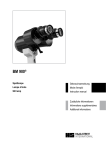
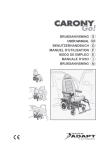
2.2 Untersuchungsteil (LS 900®)
Übersicht
1 Frontring
2 Gehäuse
3 Servicedeckel
4 Kabelabdeckung
5 Lenkhebel
6 Kreuzschlitten
7 Positionssaufkleber
8 Kopfhalter
9 Stirnband
10 Hilfsmarkierung optimale Augenhöhe
11 Kinnstütze
12 Höhenverstellung für Kinnstütze
13 Griff
2.2 La partie examen (LS 900®)
Aperçu
1 Anneau frontal
2 Boîtier
3 Cache pour les interventions de maintenance
4 Cache-câble
5 Bras de direction
6 Base d’instruments
7 Autocollant marquant la position
8 Appui-tête
9 Serre-tête
10 Marquage auxiliaire de la hauteur optimale des yeux
11 Appui-menton
12 Réglage de la hauteur de l’appui-menton
13 Poignée
© Haag-Streit AG, CH-3098 Koeniz, Switzerland
1500.7220055.04030
2.1 Grobaufbau
Das System ist in Untersuchungs- (LS 900®) und Steuerteil (Notebook, PC) unterteilt. Der Untersuchungsteil kommuniziert über eine
USB-Verbindung mit dem externen PC. Die Bedienung des LS 900®
geschieht über die auf dem PC installierte Software. Die integrierte
automatische Messfehlererkennung garantiert die Zuverlässigkeit der
Untersuchungsergebnisse.
Neue PC- und Biometriesoftware kann im Internet heruntergeladen
und aktualisiert werden.
2.1 Structure (grosso modo)
Le système est divisé en deux parties : la partie examen (LS 900®)
et la partie commande (ordinateur portable, PC). La partie destinée
à l’examen communique avec le PC externe par le biais d’une liaison
USB. La manipulation du LS 900® s’effectue par le biais du logiciel installé sur le PC. La reconnaissance automatique des erreurs de mesure
est intégrée à l’appareil et garantit ainsi la fiabilité des résultats.
Pour assurer une mise à jour régulière, il est possible de télécharger
sur Internet les nouveaux logiciels relatifs au PC et à la biométrie.
14
14
2 INTRODUCTION
2.1 Basic construction
The system is divided into two parts: one concerned with examination (LS 900®) and the other with control (Notebook, PC). The examination part communicates via a USB connection with the external
PC. The LS 900® is operated through software installed on the PC.
Integral, automatic error recognition for measurements guarantees
reliable examination results.
New PC and biometrics software can be downloaded or updated from
internet via the homepage.
2.2 Examination components (LS 900®)
Overview
1 Front ring
2 Housing
3 Service cover
4 Cable cover
5 Joystick
6 Cross slide
7 Side identification sticker
8 Headrest
9 Forehead band
10 Auxiliary marking optimal eye height
11 Chin rest
12 Chin rest height adjustment
13 Hand grips for patient
15
15
1500.7220055.04030
© Haag-Streit AG, CH-3098 Koeniz, Switzerland
Gerätestatus
Die Statusanzeige erlaubt auch ohne PC-Software das Gerät zu
überwachen:
État de l’appareil
L’affichage de l’état de l’appareil permet de surveiller l’appareil même
sans logiciel PC :
14 Statusanzeige
14 Affichage de létat
Lenkhebel
Der Lenkhebel dient zur Positionierung des Gerätes auf das Auge
des Patienten.
Bras de direction
Le bras de direction sert à positionner l’appareil sur l’œil du patient.
15 Auslöseknopf
Anschlüsse
16 USB - Geräteanschluss
17 DC - Geräteanschluss
18 USB2.0 Kabel
19 DC-Kabel
20 Zugentlastung
2.3 Steuerteil (PC)
Als Steuerteil für das Biometer wird ein handelsüblicher PC eingesetzt. Die Steuerteil-Software läuft unter WINDOWS XP.
16
15 Bouton de déclenchement
Raccordements
16 Raccordement USB
17 Raccordement DC
18 Câble USB2.0
19 Câble DC
20 Collier de fixation
2.3 Partie commande (PC)
Pour la commande du biomètre, un PC usuel est utilisé. Le logiciel
de la partie commande tourne sous WINDOWS XP.
2.3.1 Minimalanforderungen PC
• Intel CoreTM 2 Duo 2.0GHz
• RAM: 2GB (XP), 4GB (VISTA)
• 160GB Harddisk
• CD-ROM / DVD
• USB2.0 Schnittstelle (ICH5)
2.3.2 Minimalanforderungen Monitor
• 1280x800 Pixel
2.4 Instrumententisch
Ein verstellbarer Instrumententisch (Option) lässt die Höhe des Gerätes
bequem auf die individuelle Grösse der Patienten einstellen.
2.3.1 Exigences minimales PC
• Intel CoreTM 2 Duo 2.0GHz
• RAM: 2GB (XP), 4GB (VISTA)
• 160GB Harddisk
• CD-ROM / DVD
• USB2.0 Schnittstelle (ICH5)
2.3.2 Exigences minimales moniteur
• 1280x800 pixel
2.4 Table d’instruments
Une table d’instruments réglable (en option) permet de régler facilement la hauteur de l’appareil par rapport à la taille individuelle
du patient.
21
22
23
24
25
21
22
23
24
25
Tischbrett
Schublade links (für externes, medizintaugliches Netzgerät)
/ Switchbox SB01
Schublade rechts (leer)
Hubsäule (mechanisch mit Feder)
Tischfuss mit Rollen
Panneau de la table
Tiroir gauche (pour l’alimentation secteur externe adaptée aux
appareils médicaux) / Switchbox SB01
Tiroir droit (vide)
Colonne de levage (mécanique avec un ressort)
Pied de table sur roulettes
16
© Haag-Streit AG, CH-3098 Koeniz, Switzerland
1500.7220055.04030
Device state
The device state indicator allows device monitoring without PC software:
14 State indicator
Joystick
The joystick is used to position the device in relation to the patient’s
eye.
15 Trigger
Connections
16 USB – device connection
17 DC – device connection
18 USB2.0 cable
19 DC cable
20 Tension compensator
2.3 Control component (PC)
A commercial PC is used as the control component for the biometer.
Control software runs under WINDOWS XP.
2.3.1 Minimum PC requirements
• Intel CoreTM 2 Duo 2.0GHz
• RAM: 2GB (XP), 4GB (VISTA)
• 160GB Harddisk
• CD-ROM / DVD
• USB2.0 Schnittstelle (ICH5)
2.3.2 Minimum monitor requirements
• 1280x800 pixel
2.4 Instrument table
An adjustable instrument table (option) allows the height of the device
to be set comfortably to the height of the individual patient.
21 Table top
22 Left-hand drawer (for external medical power supply)
/ Switchbox SB01
23 Right-hand drawer (empty)
24 Elevator column (mechanical with spring)
25 Pedestal with castors
17
17
1500.7220055.04030
© Haag-Streit AG, CH-3098 Koeniz, Switzerland
3 INSTALLATION
3 INSTALLATION
3.1 Sichere Systemkonfiguration nach IEC / EN 60601-1
3.1 Configuration de système sûre selon IEC / EN 60601-1
ACHTUNG
Alle extern angeschlossenen Geräte müssen den
sicherheitsrelevanten Normen entsprechen.
26
27
28
29
30
31
18
Netzgerät (LS 900®)
Instrumententisch
Trenn-Transformator
Laptop / PC
Netzgerät (PC)
Drucker
ATTENTION
Tous les appareils périphériques doivent satisfaire aux normes de sécurité.
26
27
28
29
30
31
Alimentation (LS 900®)
Table d'instruments
Transformateur
PC Portable / PC
Alimentation (PC)
Imprimante
3.2 Instrumententisch
Der Instrumententisch wird in einer separaten Verpackung geliefert.
Benutzen Sie die dem Tisch beigelegte Anleitung, um den Tisch zusammenzubauen.
3.2 Table d’instruments
La table d’instruments est livrée dans un emballage séparé. Référez-vous à la notice fournie avec la table pour l’assembler correctement.
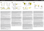
3.2.1 Montage Rollschienen/Gleitplatte
Die Position der Rollschienen/Gleitplatte muss so ausgelegt sein,
dass sich das Patientenauge, wenn das Gerät in der Mitte der Rollschiene steht, in einem Abstand von 68 mm vor der Gerätevorderseite befindet.
3.2.1 Montage des rails de roulement / de la plaque de glissement
La position des rails de roulement / de la plaque de glissement doit
être de façon à ce que l’œil du patient se trouve à une distance de
68 mm du côté frontal de l’appareil lorsque l’appareil est positionné
au milieu du rail de roulement
32
33
34
35
36
32
33
34
35
36
Rollschiene
Positionsaufkleber
Gleitplatte
Säule Kopfhalter
Kabelöffnung
Rails dentés
Etiquette de positionnement
Plaque de glissement
Pilier d'appui-tète
Ouverture pour cablage
3.2.2 Montage des Aufklebers für die automatische
Positionserkennung
• Schienendeckel entfernen und allenfalls schon platziertes Gerät
zur Seite stellen.
• Tischoberfläche reinigen.
• Entfernen Sie dies Schutzfolie (Abbildung 37) auf der AufkleberRückseite. Beginnen Sie vorsichtig in der Ecke gegenüber der weissen
Fläche.
• Dem Aufkleber mit der weissen Seite an die linke Rollschiene
(38) und die Tischkante (Abbildung 39) anschlagen. Weiss-schwarze
Fläche festpressen und Luftblasen ausstreichen.
• Den Rest des Aufklebers (Abbildung 40), (Positionierungswerkzeug
/ Positioning Tool) entlang der Perforierung vorsichtig entfernen.
3.2.2 Montage de l’autocollant pour la reconnaissance
automatique de la position
• Retirer le cache du rail et mettre de côté l’appareil s’il a déjà été
mis en place.
• Nettoyer la surface de la table.
• Retirer la feuille de protection (Figure 37) sur le verso de l’autocollant.
Commencez précautionneusement par le coin en face de la
surface blanche.
• Poser l’autocollant avec la face blanche sur le rail de roulement
gauche (38) et l’arête de la table (Figure 39). Appuyer l’autocollant sur
a face noire et blanche et le lisser jusqu’à ce que les bulles d’air
aient disparu.
• Retirer précautionneusement le reste de l’autocollant (Figure 40) (outil
de positionnement) le long de la perforation.
© Haag-Streit AG, CH-3098 Koeniz, Switzerland
1500.7220055.04030
18
3 INSTALLATION
3.1 Safe system configuration according to IEC / EN 60601-1
BEWARE
All externally connected devices must meet the
relevant safety standards.
26
27
28
29
30
31
Power supply (LS 900®)
Instrument Table
Isolation Transformer
Laptop / PC
Power supply (PC)
Printer
LAN
3.2 Instrument table
The instrument table is delivered in a separate package. To assemble
table, please use instructions enclosed with it.
3.2.1 Mounting the roller rails/slide plate
The roller rails/slide plate must be positioned in such a way that, when
the device is centred, the patient’s eye will be at a distance of 68mm
from the front of the device.
32
33
34
35
36
Rail
Positionning sticker
Gliding plate
Headrest columns
Aperture for cables
200
3.2.2 Mounting the sticker for automatic position recognition
• Take off rail cover and move the device to the side, if already
in position.
• Clean surface of table.
• Remove protective film (Figure 37) from back of sticker. Start lifting
it off carefully from the corner opposite the white area .
• Position the sticker with the white side against the right roller
rail (38) and the edge of the table (Figure 39). Press the black/white
area down firmly and stroke out any air bubbles.
• Carefully tear off the rest of the sticker (Positionierungswerkzeug/
Positioning Tool) along perforations (Figure 40).
19
19
1500.7220055.04030
© Haag-Streit AG, CH-3098 Koeniz, Switzerland
3.3 Montage Gerät
3.3 Appareil de montage
3.3.1 Heben des Gerätes
Gerät heben oder umplatzieren (nur kurze Wege):
a)Gerät von hinten mit einer Hand bei der Säule fassen und hoch heben (Abbildung 41).
b)mit der zweiten Hand am Kreuzschlitten unterstützen
(Abbildung 42).
3.3.1 Levage de l’appareil
Soulever l’appareil et le faire changer de place (uniquement sur des
distances courtes) :
a)Saisir l’appareil par derrière (par la colonne) avec une seule main
et le soulever (Figure 41).
b)soutenir la base d’instruments avec l’autre main (Figure 42).
3.3.2 Verkabelung untenliegende Kabelführung
Sie haben die Möglichkeit die Verkabelung zum Gerät – mittels der
untenliegenden Kabelführung durch den Kreuzschlitten – unsichtbar
zu gestalten. Dazu benötigen sie entweder den Haag-Streit Instrumententisch HSM901 oder eine Öffnung im verwendeten Tischbrett.
• Kabelabdeckung entfernen (Abbildung 43)
• USB- und Speisekabel freilegen (Tischöffnung, Abbildung 44)
• Speisekabel durch Öffnung unten am Kreuzschlitten einfahren
bis Kabel bei der vorderen obigen Öffnung herausschaut
(Abbildung 45)
• USB-Kabel durch gleiche Öffnung am Kreuzschlitten einfahren
(Abbildung 45)
• Beide Kabel in die entsprechenden Buchsen einstecken und mit
der Zugentlastung fixieren (Abbildung 46)
• Kabelabdeckung aufsetzen (Abbildung 47)
3.3.2 Câblage du conduit pour câbles situé sur le côté
inférieur
Vous avez la possibilité de dissimuler le câblage de l’appareil en faisant passer le conduit pour câbles par la base d’instruments. Vous
avez besoin pour cela de la table d’instruments Haag-Streit HSM901
ou d'une ouverture dans le panneau de la table utilisée.
• Retirer le cache-câble (Figure 43 )
• Dégager le câble USB et le câble d’alimentation (ouverture de
la table, Figure 44 )
• Faire passer le câble d’alimentation par l’ouverture située en
bas de la base d’instruments jusqu’à ce que le câble apparaisse
à l’ouverture antérieure en haut (Figure 45 )
• Faire passer le câble USB par la même ouverture sur la base
d’instruments (Figure 45 )
• Raccorder les deux câbles aux prises femelles correspondantes
et les fixer à l’aide du collier de fixation (Figure 46 )
• Poser le cache-câble (Figure 47 )
© Haag-Streit AG, CH-3098 Koeniz, Switzerland
1500.7220055.04030
20
20
3.3 Mounting the device
3.3.1 Lifting the device
To lift or reposition the device (short distances only):
a)Grasp device from behind with one hand on the column and lift (Figure 41).
b)With the second hand, support under the cross-slide
(Figure 42).
3.3.2 Wiring cable under the device
The device can be invisibly wired by passing cables through the
cross-slide and using the cable channel underneath. To do this, you
need either the Haag-Streit instrument table HSM901 with table-top
biometer, or an aperture in the table-top used.
• Remove cable cover (Figure 43)
• Expose USB and supply cables (table aperture, Figure 44)
• Push supply cable through aperture in base of cross-slide until
the cable emerges from the upper front aperture (Figure 45)
• Push USB cable through the same aperture in the cross-slide
(Figure 45)
• Plug both cables into the corresponding boxes and fix with the
tension compensator (Figure 46)
• Replace cable cover (Figure 47)
21
21
1500.7220055.04030
© Haag-Streit AG, CH-3098 Koeniz, Switzerland
3.3.3 Gerät anschliessen, seitliche Kabelführung (Option)
• Kabelabdeckung entfernen (Abbildung 48)
• USB- und Speisekabel freilegen (linke oder rechte Öffnung beim
Schienendeckel)
• Mit einem Messer die Sollbruchstelle links oder rechts an der
Kabelabdeckung vorsichtig einschneiden (Abbildung 49)
• Vorsichtig das angeschnittene Teil mit den Fingern herausbre chen (Abbildung 50)
• Beide Kabel in die entsprechenden Buchsen einstecken und mit
der Zugentlastung fixieren
• Beide Kabel mit ’Spiralkabel’ zusammenfügen und mittels der
Kabelführung am Schienendeckel befestigen (Abbildung 51)
• Kabelabdeckung aufsetzen
3.3.3 Raccorder l’appareil, conduit pour câble latéral (Option)
• Retirer le cache-câble (Figure 48 )
• Dégager le câble USB et le câble d’alimentation (ouverture gau che ou droite au niveau du cache-rails)
• Inciser précautionneusement à l’aide d’un couteau le point de
rupture théorique à gauche ou à droite du cache-câble
(Figure 49 )
• Détacher précautionneusement avec les doigts l’élément incisé
(Figure 50 )
• Raccorder les deux câbles aux prises femelles correspondantes
et les fixer à l’aide du collier de fixation
• Assembler les deux câbles à l’aide d’un ‘câble spirale’ et les fixer
à l’aide du conduit pour câbles sur le cache-rails (Figure 51 )
• Mettre en place le cache-câble
3.4 Computer anschliessen
• Verbinden Sie LS 900® und PC mit dem beiligenden USB2.0
Kabel. Es wird empfohlen das mitgelieferte 2m Kabel zu
verwenden.
3.4 Raccordement de l’ordinateur
• Raccordez le LS 900® et le PC à l’aide du câble USB2.0 fourni.
Il est recommandé d’utiliser le câble de 2 m fourni.
ACHTUNG
Das USB Kabel darf die Länge von 5m nicht
überschreiten, anderenfalls muss mit einer
Beeinträchtigung der Gerätefunktion gerechnet werden.
ATTENTION
Le câble USB ne doit pas dépasser une longueur
de 5 m pour éviter toute altération du bon fonctionnement de l’appareil.
• Netzkabel einstecken. Die eingebauten Netzteile arbeiten mit
den im Kapitel 7.1 'Technische Daten' spezifizierten Spannungen.
Eine Spannungswahl am Gerät ist nicht erforderlich.
• Falls ein Instrumententisch mitgeliefert wurde, kann das Netzgerät
des LS 900® an die Switchbox SB01 (linke Schublade) angeschlossen werden. Benutzen Sie die der Switchbox und Tisch beigelegten
Anleitung.
3.4.1 Software
Installieren Sie die Software gemäss separater Beschreibung 'Setup Guide'.
• Raccorder le câble d’alimentation. Les blocs d’alimentation
intégrés fonctionnent avec les tensions spécifiées au chapitre 7.1. Il n’est pas nécessaire de sélectionner la tension sur
l’appareil.
• Si la livraison comprend une table d’instruments, il est
possible de raccorder l’alimentation secteur du LS 900® au commutateur SB01 (tiroir de gauche). Utilisez le mode d'emploi joint au commutateur et à la table d’instruments.
3.4.1 Logiciel
Installez le logiciel conformément à la notice séparée 'Setup Guide'.
© Haag-Streit AG, CH-3098 Koeniz, Switzerland
1500.7220055.04030
22
22
3.3.3 Device connection, cables at side (Option)
• Remove cable cover (Figure 48)
• Expose USB and supply cables (left or right aperture on rail
cover)
• With a knife, cut towards the snap-off point provided on the left
or right of the cable cover (Figure 49)
• Carefully use fingers to snap off the cut part (Figure 50)
• Insert both cables in the appropriate box and fix with the tension
compensator.
• Join both cables together with spiral cable and attach firmly using
the cable channel on the rail cover (Figure 51)
• Replace cable cover
48
3.4 Computer connection
• Connect the LS 900® to the PC with the enclosed USB2.0 cable.
Use of the 2 m cable supplied with delivery is recommended.
BEWARE
The USB cable should not exceed 5 m in length,
otherwise impairment of device function must
be expected.
• Insert mains cable. Integral mains components work with the voltages specified under section 7.1 'Technical data'. It is not necessary
to select the voltage on the device.
• If an instrument table has been supplied, the power supply of the
LS 900® can beconnected to the Switchbox SB01 (left drawer). Use the
manual enclosed to the switchbox and the instrument table.
3.4.1 Software
Install software in accordance with separately described 'Software
Installation'.
49
23
50
23
51
1500.7220055.04030
© Haag-Streit AG, CH-3098 Koeniz, Switzerland
4 BEDIENUNG
4 MANIPULATION
4.2 Fixation
Um sinnvolle Messresultate zu erhalten, muss der Patient während
der Messung das rote Fixationslicht im Messobjektiv fixieren. Hat
der Patient Schwierigkeiten, mit dem gemessenen Auge das Fixationslicht zu sehen, so kann behelfsmässig mit dem Partnerauge ein
entferntes gegenüberliegendes Objekt fixiert werden.
4.2 Fixation
Afin d’obtenir des résultats de mesure utiles, le patient doit fixer la
lumière de fixation rouge dans l’objectif de mesure pendant la durée
de la mesure. Si le patient éprouve des difficultés à fixer la lumière
de fixation avec l’œil mesuré, il peut provisoirement fixer avec l’autre
œil un objet éloigné situé face à lui.
Um periphere Messungen der Hornhautdicke vorzunehmen, stehen
32 grüne Fixationspunkte zur Verfügung. Diese können per Software
ein-, bzw. ausgeschaltet werden. Die Punkte sind auf 2 Ringen verteilt. Beim Fixieren des Patienten auf diese Punkte (Abbildung 53),
wird eine periphere Zone mit folgenden Abständen (a) zur horizontalen Achse vermessen (Normauge R=7.8mm):
Äusserer Abstand: 2.7 mm
Innerer Abstand: 2 mm
b:Fixation peripher
c: Auge
d:Fixation zentral (Messtrahl, rot)
Pour effectuer des mesures périphériques de l’épaisseur de la cornée, 32 points de fixation verts sont disponibles. Il est possible de les
allumer ou de les éteindre via le logiciel. Les points sont répartis sur
2 anneaux. En fixant le patient sur ces points (Figure 53), on mesure une zone périphérique avec les écarts suivants (a) par rapport à
l’axe horizontal (œil normal R = 7,8 mm) :
écart extérieur : 2,7 mm
écart intérieur : 2 mm
B:Fixation périphérique
c: Oeil
d:Fixation centrale (faisceau de mesure, rouge)
4.3 Messgrössen
4.3.1 A-Scan
Gegeben durch das patientenseitige Fixieren des Fixationslichts, wird
die optische Weglänge der Sehachse vermessen. (Abbildung 54)
CT: Korneadicke
AD:Kammerwassertiefe (Kornearückseite bis Linsenvorderseite)
LT: Linsendicke
AL: Achslänge (Korneavorderseite bis retinales Pigmentepithel)
Bemerkung: Je nach gewähltem Modus der Software wird die Achslänge nur bis zur inneren Grenzmembran (d.h. retinales Pigmentepithel – 0.2mm) angegeben.
4.3 Grandeurs de mesure
4.3.1 A-Scan :
Le trajet optique de l’axe visuel est mesuré lorsque le patient fixe la
lumière de fixation. (Figure 54)
CT : épaisseur de la cornée
AD : Profondeur humeur aqueuse (du côté postérieur de
la cornée au côté antérieur de la lentille)
LT : épaisseur de la lentille
AL: longueur axiale (du côté antérieur de la cornée à
l’épithéliumrétinal de la cornée)
Remarque : Selon le mode sélectionné du logiciel, la longueur axiale
n’est indiquée que jusqu’à la membrane limitante intérieure (c'est-àdire l’épithélium rétinal de la cornée – 0.2mm).
4.1 Messposition des Patienten
Die Positionierung des Gerätes wird manuell vom Benutzer durchgeführt. Der Patient muss so positioniert werden, dass der Abstand vom
Messkopf zum Auge ca. 68mm beträgt (Abbildung 52). Gute Auflage
des Patientenkopfes auf Kinnstütze und Stirnband, sowie das Festhalten der beiden seitlichen Griffe durch den Patienten fördern die
ruhige Position des Kopfes. Dies kann sich positiv auf Justierdauer
und Genauigkeit der Messung auswirken.
24
24
4.3.2 Keratometrie
Die Keratometrie wird über die Position von 32 projizierten Lichtreflexen berechnet. Je 16 Messpunkte auf dem Auge liegen auf 2 Ringen
mit Durchmesser (Normauge R=7.8mm):
Äussere Messpunkte: 2.3 mm
Innere Messpunkte:
1.65 mm
Für jeden Messpunkt wird das Äquivalent einer idealen Sphäre berechnet.
Die angezeigten Werte, flacher Radius, steiler Radius entsprechen
den Radien eines in die Punkteschar eingepassten Ellipsoids. Die
Achslage ist von der Horizontalen zum flachen Radius gemessen.
(Abbildung 55)
e:Flacher Radius
f: Steiler Radius
g:Achslage
© Haag-Streit AG, CH-3098 Koeniz, Switzerland
4.1 Position de mesure du patient
Le positionnement de l'appareil est effectuée manuellement par
l'utilisateur. Le patient doit être positionné de façon à ce que la distance entre la tête de mesure et l'œil comporte 68 mm (Figure 52).
Si la tête du patient repose bien sur l’appui-menton et le serre-tête et
que le patient tient les deux poignées latérales, la tête risque moins
de bouger. Cela a un effet positif sur la durée de l’ajustement et la
précision de la mesure.
4.3.2 Kératométrie
La kératométrie est calculée via la position de 32 reflets de lumière
projetés. 16 points de mesure par œil reposent sur 2 anneaux avec
un diamètre (œil normal R = 7,8 mm) de :
Points de mesure extérieurs : 2,3 mm
Points de mesure intérieurs : 1,65 mm
Pour chaque point de mesure, l’équivalent d’une sphère idéale est
calculé.
Les valeurs affichées - première section principale, deuxième section principale - correspondent aux rayons d’un ellipsoïde ajusté à la
foule de points de mesure. La position de l’axe est mesurée depuis
la ligne horizontale par rapport au rayon plat. (Figure 55)
e:Première section principale
f: Deuxième section principale
g:Position de l’axe
1500.7220055.04030
4 OPERATION
4.1 Position of patient during measurement
The positioning of the device is done manually by the user. The patient must be positioned in such a way that the distance from the
measuring head to the eye is approx. 68 mm (Figure 52). A steady
head position is promoted by resting the patient’s head well against
the chin rest and forehead band, and by the patient holding on to the
handles supplied. This can positively influence adjustment time and
measuring accuracy.
4.2 Fixation
To obtain usable results, the patient must stare at the red fixation light
in the measuring lens during measurement. If the patient has difficulty seeing the fixation light with the eye being measured, this can be
remedied by fixing the other eye on an opposed remote object.
To carry out peripheral measurement of corneal thickness, 32 green
fixation points are provided. These can be switched on or off by software. The points are arranged in 2 rings. When the patient stares
at these points (Figure 53), a peripheral zone is measured with the
following distances (a) from the horizontal axis (standard eye R =
7.8 mm):
Outer distance: 2.7 mm
Inner distance:
2 mm
b:Fixation periphery
c: Eye
d:Fixation center (Measurement beam, red)
4.3 Measured variables
4.3.1 A-Scan
Depending on the patient’s gaze at the fixation light, the optical path
length of the visual axis is measured. (Figure 54)
CT: Corneal thickness
AD:Aqueous depth (back of cornea to front of lens)
LT: Lens thickness
AL: Eye length (front of cornea to retinal peak)
Note: Depending on the chosen software mode, eye length is indicated to the inner limiting membrane (retinal pigment epithelium
– 0.2 mm).
25
4.3.2 Keratometry
Keratometry is calculated through the position of 32 projected light
reflections. Sixteen measuring points on each eye are arranged in two
rings with the following diameters (standard eye R = 7.8 mm):
Outer measuring points: 2.3 mm
Inner measuring points:
1.65 mm
For each measuring point, the equivalent of an ideal sphere is calculated.
The values displayed (flat radius, steep radius) correspond to the
radii of an ellipsoid that fits into the assemblage of points. The axis
of its rotation is measured counter-clockwise from the horizontal to
the flat radius. (Figure 54)
e:Flat radius
f: Steep radius
g:Axis of its rotation
1500.7220055.04030
AD
© Haag-Streit AG, CH-3098 Koeniz, Switzerland
25
4.3.3 Weiss-Weiss Abstand
Der Weiss-Weiss (WW) Abstand wird anhand des Irisbildes sowie der
durch die Keratometrie gefundenen Augenradien ermittelt.
Der angezeigte Wert entspricht dem Durchmesser eines idealen
Kreises. (Abbildung 56)
4.3.4 Pupillometrie & Sehachse
Der Pupillendurchmesser (Ø) entspricht dem Durchmesser eines
idealen Kreises mit dem kleinsten Fehlerquadrat zum gefundenen
Pupillenrand. Gleichzeitig wird die Verschiebung der Sehachse zum
Pupillenzentrum ausgegeben. Die berechnete Dimension liegt auf der
theoretisch errechneten Ebene der Iris. Eine Vergrösserung des Bildes,
gegeben durch die Brechung des Auges wird nicht berücksichtigt.
(Abbildung 57)
4.3.3 Écart blanc-blanc
L’écart blanc-blanc (WW) est déterminé à partir de l’image de l’iris et
des rayons de l’œil définis à l’aide de la kératométrie.
La valeur affichée correspond au diamètre d’un cercle idéal.
(Figure 56)
5 BEDIENUNGSANLEITUNG
SOFTWARE
5 MODE D’EMPLOI DU LOGICIEL
Die Bedienung des Gerätes zur Durchführung einer Untersuchung,
sowie die Beschreibung der Anwendersoftware EyeSuiteTM ist in einer separaten Anleitung beschrieben.
6 PFLEGE UND UNTERHALT
ACHTUNG
26
26
• Gehäuseteile des Biometers dürfen nur von
geschultem Personal entfernt werden.
• Vor dem Entfernen von Gehäuseteilen muss das
Gerät durch Ausstecken des Netzkabels zwingend
vom Stromnetz getrennt werden.
• Reparaturen dürfen nur von entsprechend
ausgebildetem und autorisiertem Fachpersonal
durchgeführt werden. Durch unsachgemässe
Reparaturen können erhebliche Gefahren für
Patienten und Bedienungspersonen entstehen.
• Falls Teile ersetzt werden müssen, dürfen nur von
HAAG-STREIT bzw. Ihrem Vertreter gelieferte
Original-Ersatzteile eingebaut werden.
• Garantieansprüche können nicht geltend gemacht
werden, wenn Anweisungen in der Gebrauchsanweisung missachtet werden.
4.3.4 Pupillométrie & axe visuel
Le diamètre de la pupille (Ø) correspond au diamètre d'un cercle idéal
avec le plus petit carré des erreurs par rapport au bord de la pupille
trouvé. Simultanément, le décalage de l’axe visuel par rapport au centre de la pupille est édité. La dimension calculée se situe sur le niveau
de l’iris calculé théoriquement. Un agrandissement de l’image donné
par la réfraction de l’œil n’est pas pris en compte (Figure 57)
La manipulation de l’appareil pour effectuer un examen ainsi que le
logiciel d’utilisateur EyeSuiteTM sont décrits séparément.
6 ENTRETIEN ET MAINTENANCE
ATTENTION
• Les éléments du boîtier du biomètre ne doivent être
retirés que par un personnel qualifié.
• Avant de retirer des éléments du boîtier, l'appareil
doit impérativement être coupé du réseau (débrancher le câble d’alimentation).
• Seul un personnel suffisamment qualifié et autorisé est habilité à effectuer des réparations.
Des réparations inappropriées peuvent entraîner
des risques importants pour les patients et les
opérateurs.
• Si le remplacement de pièces est nécessaire, seul
HAAG-STREIT ou son représentant est autorisé à
effectuer le montage de pièces d’origine.
• L’utilisateur ne peut pas bénéficier de la garantie si
les instructions de la notice d’utilisation ne sont pas
respectées.
Der LS 900® ist praktisch wartungsfrei und benötigt eine minimale
Pflege, um lange zur vollsten Zufriedenheit zu arbeiten. Wir empfehlen
dennoch, das Biometer durch Service-Techniker periodisch überholen zu lassen. HAAG-STREIT oder Ihre lokale Vertretung gibt Ihnen
dazu gerne nähere Auskunft.
Le LS 900® ne nécessite pratiquement aucune maintenance ; seul un
entretien minimal est nécessaire pour assurer un parfait fonctionnement
pendant longtemps. Nous recommandons toutefois de faire réviser
le biomètre régulièrement par un technicien SAV. HAAG-STREIT ou
votre représentation locale vous renseignera volontiers à ce sujet
6.1 Funktionsüberprüfung
Die zum Gerät mitgelieferte Prüflehre (Abbildung 58) dient dem Benutzer zur Überprüfung der Funktionstüchtigkeit des Gerätes. Die
Überprüfung erfolgt erstmals bei der Inbetriebnahme des Gerätes.
Anschliessend wird das Intervall (1 Woche) von der Software vorgegeben (Meldung erscheint). Genauer Ablauf siehe ’Bedienungsanleitung Software’.
6.1 Vérification du bon fonctionnement
La jauge de vérification (Figure 58) fournie avec l’appareil permet à
l’utilisateur de vérifier le bon fonctionnement de l’appareil. La vérification
est effectuée la première fois lors de la mise en service de l’appareil.
Par la suite, les intervalles de vérification (1 semaine) sont indiqués
par le logiciel (un message correspondant s’affiche). Pour connaître
le déroulement exact, voir le ‘Mode d’emploi du logiciel’.
Sollte die Prüfung nicht innerhalb der Toleranzen liegen, so erscheint
eine Softwaremeldung und das Gerät ist ausser Betrieb zu nehmen.
Verständigen Sie den Haag-Streit Service.
Si le résultat de la vérification ne se situe pas à l’intérieur des marges
de tolérance, le logiciel affiche un message et l’appareil doit être mis
hors service. Informez le service après-vente de Haag-Streit.
© Haag-Streit AG, CH-3098 Koeniz, Switzerland
1500.7220055.04030
4.3.3 White-to-white distance
The white-to-white distance (WW) is determined using the image of
the iris and the eye radii obtained from keratometry.
The value displayed corresponds to the diameter of an ideal circle.
(Figure 56)
4.3.4 Pupillometry and visual axis
Pupil diameter (Ø) corresponds to the diameter of an ideal circle,
with the smallest error square to the established pupil border. At the
same time, the shift of visual axis towards the centre of the pupil is
provided. The calculated dimensions are located on the theoretically
derived level of the iris. Image enlargement achieved by breaking up
the eye is disregarded. (Figure 57)
5 SOFTWARE GUIDE
Device operation for carrying out an examination is set out in a separate guide, together with a description of EyeSuiteTM application
software
6 CARE AND MAINTENANCE
BEWARE
• Biometer housing parts should only be removed by
trained personnel.
• The ON/OFF switch does not disconnect the biometer from the mains. Before removing housing
parts, the device must always be disconnected from
mains power by unplugging the mains power cable.
• Repairs should only be undertaken by suitably
trained, authorized, technical staff. Improper repairs
may result in considerable risk to patient and operator.
• If parts must be replaced, only original spare parts
supplied by HAAG-STREIT or its agent should be
used.
• Guarantee claims cannot be enforced if instructions
in the User Guide have been ignored.
27
The LS 900® is practically maintenance free and only requires minimal care to provide complete satisfaction over a long working life.
However, we recommend instructing a service engineer to overhaul
the biometer periodically. HAAG-STREIT or your local agent will be
happy to provide further information.
6.1 Function check
The inspection gauge (Figure 58) supplied with the device will assist
the user in checking the proper functioning of the unit. This check
takes place for the first time when the device is commissioned. Subsequent test intervals (1 week) will be specified by the software (message displayed). For exact procedure see software guide.
27
If test results fall outside tolerances, a corresponding message will
be displayed and the device should be taken out of service. Please
inform Haag-Streit Service.
1500.7220055.04030
© Haag-Streit AG, CH-3098 Koeniz, Switzerland
6.2 Reinigung
Es genügt, das Gerät periodisch mit einem weichen Tuch abzustauben. Hartnäckigere Schmutzpartikel können mit einem mit Wasser
oder max. 70%-igen Alkohol befeuchteten, nicht tropfenden Tuch
entfernt werden.
!
VORSICHT
Vermeiden Sie, das Gerät nass zu machen und verwenden Sie
ausschliesslich die oben angegebenen Mittel und unter keinen
Umständen Lösungsmittel oder andere scheuernde Mittel.
Im Zubehör des LS 900® liegt eine Überwurfhülle bei. Decken Sie
das Gerät während Reinigungsarbeiten oder wenn es für längere
Zeit nicht benutzt wird, zu. Vor dem Einschalten des Gerätes muss
die Überwurfhülle entfernt werden.
!
28
28
VORSICHT
VORSICHT
Das
Gerät darf
im eingeschalteten
Zustand
zugedeckt
Vermeiden
Sie, nicht
das Gerät
nass zu machen
und verwenden
werden
(Wärmestau,
Brandgefahr).
Sie unter
keinen Umständen
Lösungsmittel oder andere
scheuernde Mittel.
6.2 Nettoyage
Il suffit de dépoussiérer l’appareil régulièrement avec un chiffon doux.
Pour enlever des particules de saleté persévérants, il suffit d’utiliser
un chiffon doux non-ruissellant, humidifié avec de l’eau ou de l’alcool
a maximum 70%.
!
PRÉCAUTION
Évitez de mouiller l’appareil et utilisez exclusivement les moyens indiqués ci-dessus. N’utilisez en aucun cas des solvants
ou d’autres produits récurants.
Une housse de protection est fournie avec les accessoires du LS
900®. Recouvrez l’appareil pendant le nettoyage des locaux ou s’il
n’est pas utilisé pendant longtemps. Avant d’allumer l’appareil, il faut
retirer la housse de protection.
!
PRÉCAUTION
PRÉCAUTION
Ne
pasderecouvrir
alluméen
(accumulation
de
Évitez
mouillerl’appareil
l’appareils’ilet est
n’utilisez
aucun cas des
chaleur,
d’incendie).
solvants risque
ou d’autres
produits récurants.
7 ANHANG
7 ANNEXE
© Haag-Streit AG, CH-3098 Koeniz, Switzerland
1500.7220055.04030
7.1 Technische Daten
Hersteller
HAAG-STREIT AG
Gartenstadtstrasse 10
CH-3098 Köniz / Schweiz
7.1.1 Allgemeines
Typenbezeichnung:
LS 900®
Abmessungen (B x T x H):
310 x 260 x 420 mm
Gewicht:
6.2 kg
7.1.2 Elektrische Angaben
7.1.2.1 Netzgerät (primäre Seite)
Netzgerät:
Medizinisch zugelassen nach
EN / IEC60601-1
HS-Nr.:1020392, Friwo FW7401M/12
7.1.2.2 Gerät (sekundäre Seite)
Spannung:
12 V
Leistungsaufnahme:
12 W
7.1.3 Optische Strahlung
7.1.3.1 Achslängenmessung (A-Scan) und zentrale Fixation
Lichtquelle:
Superlumineszenzdiode
Wellenlänge:
820nm
Leistung auf Patientenauge:
< 0.6 mW
max. Belastung pro Patient und Tag:
30’000 s
7.1.3.2 Keratometrie
Lichtquelle:
LED
Wellenlänge:
950nm
Leistung auf Patientenauge:
< 0.2 mW
max. Belastung pro Patient und Tag:
30’000 s
7.1.3.3 Periphere Fixation
Lichtquelle:
LED
Wellenlänge:
570 nm
Leistung auf Patientenauge:
< 0.02 mW
max. Belastung pro Patient und Tag:
30'000 s
7.1.3.4 Grünbeleuchtung
Lichtquelle:
LED
Wellenlänge:
525 nm
Leistung auf Patientenauge:
< 0.2 mW
max. Belastung pro Patient und Tag:
600 s
Die Kombination der erzeugten Strahlung liegt unterhalb der von IEC
60825-1 geforderten Grenzwerten der Laserklasse 1.
7.1 Caractéristiques techniques
Fabricant
HAAG-STREIT AG
Gartenstadtstrasse 10
CH-3098 Köniz / Suisse
7.1.1 Généralités
Désignation du type d’instrument :
LS 900®
Dimensions (L x P x H) :
310 x 260 x 420 mm
Poids :
6,2 kg
7.1.2 Données électriques
7.1.2.1 Alimentation secteur (côté primaire)
Alimentation secteur :Adaptée aux appareils médicaux
selon EN / IEC60601-1
N° HS : 1020392, Friwo FW7401M/12
7.1.2.2 Appareil (côté secondaire)
Tension :
12 V
Puissance d’entrée :
12 W
7.1.3 Rayonnement optique
7.1.3.1 Mesure de la longueur axiale (A-Scan) et fixation centrale
Source lumineuse:
diode superluminiscente
Longueur d’onde:
820 nm
Performance exercée sur l’œil du patient: < 0,6 mW
Charge maximale par patient et par jour: 30’000 s
7.1.3.2 Kératométrie
Source lumineuse:
DEL
Longueur d’onde:
950 nm
Performance exercée sur l’œil du patient: < 0,2 mW
Charge maximale par patient et par jour: 30’000 s
7.1.3.3 Fixation périphérique
Source lumineuse:
DEL
Longueur d’onde:
570 nm
Performance exercée sur l’œil du patient: < 0,02 mW
Charge maximale par patient et par jour: 30'000 s
7.1.3.4 Éclairage vert
Source lumineuse:
DEL
Longueur d’onde:
525 nm
Performance exercée sur l’œil du patient: < 0,2 mW
Charge maximale par patient et par jour: 600 s
La combinaison du rayonnement généré est inférieure aux valeurs
limites exigées par IEC 60825-1 pour la classe laser 1.
6.2 Cleaning
Regular dusting of the device with a soft cloth is sufficient. More stubborn dirt can be removed using a soft, non-runoff cloth dampened
with water or alcohol at maximum 70%.
!
CAUTION
Avoid making the device wet and use only the means listed
above. Under no circumstances use solvent or any other abrasive methods.
The accessories of the LS 900® include a dust cover. Cover the device when cleaning work is in progress, or if the devices is not in
use for long periods. Before switching the device on, the dust cover
must be removed.
!
CAUTION
CAUTION
The
not bewet
covered
whennoitscircumstances
state is switched
Avoiddevice
makingmust
the device
and under
use
on
(heatordam,
risk).
solvent
any fire
other
abrasive methods.
7 APPENDIX
7.1 Technical data
Manufacturer
HAAG-STREIT AG
Gartenstadtstrasse 10
CH-3098 Köniz / Switzerland
7.1.1 General
Type designation:
LS 900®
Dimensions (W x D x H):
310 x 260 x 420 mm
Weight:
6.2 kg
7.1.2 Electrical data
7.1.2.1 Power supply (primary side)
Power supply:
Compliant
EN / IEC60601-1
HS-Nr.:1020392, Friwo FW7401M/12
7.1.2.2 Device (secondary side)
Voltage:
12 V
Power draw:
12 W
29
7.1.3
Optical radiation
7.1.3.1 Eye length measurement (A-Scan) and central fixation
Light source:
Superlum. diode
Wave length:
820nm
Power on patient’s eye:
< 0.6 mW
max. exposure per patient/day:
30 000 s
7.1.3.2 Keratometry
Light source:
LED
Wave length:
950nm
Power on patient’s eye:
< 0.2 mW
max. exposure per patient/day:
30 000 s
7.1.3.3 Peripheral fixation
Light source:
LED
Wave length:
570 nm
Power on patient’s eye:
< 0.02 mW
max. exposure per patient/day:
30 000 s
7.1.3.4 Green illumination
Light source:
LED
Wave length:
525 nm
Power on patient’s eye:
< 0.2 mW
max. exposure per patient/day:
600 s
The combination of radiation generated corresponds to laser class I,
1500.7220055.04030
29
© Haag-Streit AG, CH-3098 Koeniz, Switzerland
30
30
7.1.4 Messgrössen
Die Grössen beziehen sich auf den Messmodus ’Phak’.
7.1.4.1 Hornhautdicke (CT)
Messbereich:
300 – 800 µm
Anzeigeauflösung:
1 µm
In-vivo Reproduzierbarkeit (1.SD):
±2.3 µm
7.1.4.2 Vorderkammertiefe (ACD)
Messbereich:
1.5 - 5.5 mm
Anzeigeauflösung:
0.01 mm
In-vivo Reproduzierbarkeit (1.SD):
±0.04 mm
7.1.4.3 Linsendicke (LT)
Messbereich:
0.5 – 6.5 mm
Anzeigeauflösung:
0.01 mm
In-vivo Reproduzierbarkeit (1.SD):
±0.08 mm
7.1.4.4 Achslänge (AL)
Messbereich:
14 – 32 mm
Anzeigeauflösung:
0.01 mm
In-vivo Reproduzierbarkeit (1.SD):
±0.035 mm
7.1.4.5 Keratometrie (R)
Messbereich Radius:
5 – 10.5 mm
Anzeigeauflösung:
0.01 mm
In-vivo Reproduzierbarkeit (1.SD):
±0.03 mm
Messbereich Achswinkel:
0-180°
Anzeigeauflösung:
1°
In-vivo Reproduzierbarkeit (1.SD)
±11°
7.1.4.6 Weiss-Weiss-Abstand (WTW)
Messbereich:
7 - 16 mm
Anzeigeauflösung:
0.01 mm
In-vivo Reproduzierbarkeit (1.SD):
±0.04 mm
7.1.4.7 Pupillometrie
Messbereich:
2 – 13 mm
Anzeigeauflösung:
0.01 mm
Die oben angegebenen Messbereiche entsprechen der Standardeinstellung der automatischen Auswertung. Die angegebenen in-vivo
Reproduzierbarkeiten wurden in einer klinischen Studie an Kataraktpatienten ermittelt. (Siehe Tab. 1 und 2)
7.1.4.8 Studiendesign
Die klinische Studie zur Ableitung der in-vivo Reproduzierbarkeit wurde
von der lokalen Ethikkommission genehmigt. Es wurde entwickelt, und
als eine prospektive, nicht gemischte Vergleichsstudie durchgeführt.
Der genehmigte Prüfungsplan, die in Studienphase 1 Messungen der
axialen Länge (AL), die zentrale Hornhautdicke (CT), Vorderkammertiefe (ACD), Zentral-Linsen (LT), Mittelwert Hornhautradius (R), und
die Achse des flachen Meridian. In der genehmigten Studienphase
2 wurde der Weiss -Weiss Abstand gemessen. Insgesamt wurden
144 Augen von 80 Probanden in der Studienphase 1, und 40 Augen
von 20 Probanden in der Studienphase 2 gemessen.
7.1.5 Umweltbedingungen
7.1.5.1 Gebrauch
Temperatur:
+10°C bis +35°C
Relative Feuchte:
30% bis 75%
Luftdruck:
800hPa bis 1060hPa
7.1.5.2 Lagerung
Temperatur:
-10°C bis +55°C
Relative Feuchte:
10% bis 95%
Luftdruck:
700hPa bis 1060hPa
7.1.4.3 Transport
Temperatur:
-40°C bis +70°C
Relative Feuchte:
10% bis 95%
Luftdruck:
500hPa bis 1060hPa
7.1.6 Klassierung/Sicherheitsbestimmungen
IEC / EN 60601-1:
Biometer LS 900®
Anwendungsteil Typ B
Betriebsart: Dauerbetrieb
IEC / EN 60601-1-2:
EMV
IEC 60825-1:
Laser Klasse I
7.1.4 Grandeurs de mesure
Les grandeurs se réfèrent aux mode de mesure « Phak ».
7.1.4.1 Épaisseur de la cornée (CT)
Plage de mesure:
300 à 800 μm
Résolution de l’affichage:
1 µm
Reproductibilité in vivo (1.SD):
±2.3 µm
7.1.4.2 Profondeur de la chambre antérieure (ACD)
Plage de mesure:
1,5 à 5,5 mm
Résolution de l’affichage:
0,01 mm
Reproductibilité in vivo (1.SD):
±0.04 mm
7.1.4.3 Épaisseur de la lentille (LT)
Plage de mesure:
0,5 à 6,5 mm
Résolution de l’affichage:
0,01 mm
Reproductibilité in vivo (1.SD):
±0.08 mm
7.1.4.4 Longueur de l’axe (AL)
Plage de mesure:
14 à 32 mm
Résolution de l’affichage:
0,01 mm
Reproductibilité in vivo (1.SD):
±0.035 mm
7.1.4.5 Kératométrie (R)
Plage de mesure rayon:
5 à 10,5 mm
Résolution de l’affichage:
0,01 mm
Reproductibilité in vivo (1.SD):
±0.03 mm
Plage de mesure angle axial:
0-180°
Résolution de l’affichage:
1°
Reproductibilité in vivo (1.SD):
±11°
7.1.4.6 Écart blanc-blanc (WTW)
Plage de mesure:
7 à 16 mm
Résolution de l’affichage:
0,01 mm
Reproductibilité in vivo (1.SD):
±0.04 mm
7.1.4.7 Pupillométrie
Plage de mesure:
2 à 13 mm
Résolution de l’affichage:
0,01 mm
Les plages de mesure indiquées ci-dessus correspondent au réglage
par défaut de l’évaluation automatique. Les valeurs de reproductibilité in vivo indiquées ci-dessus ont été déterminées dans une étude
clinique sur des patients atteints de cataractes.(voir tab. 1 et 2)
7.1.4.8 Conception de l'étude
L'étude clinique qui a été utilisée pour dériver la reproductibilité invivo, a été approuvé par le comité d'éthique local. Elle a été conçue
et réalisée dans une étude prospective non-mixte comparative. Le
plan de vérification de l'étude approuvée phase 1 comprend des mesures de longueur axiale (AL), d'épaisseur cornéenne centrale (CT),
de profondeur de la chambre antérieure (ACD), lentille centrale (LT),
rayon moyen de la cornée (R), et l'axe du méridien plat. Dans l'étude
approuvée phase 2 , la distance blanc-blanc a été mesurée. Un total
de 144 yeux de 80 sujets à l'étude phase 1, et 40 yeux de 20 sujets
à l'étude phase 2 ont etés mesurés.
7.1.5 Conditions environnementales
7.1.5.1 Utilisation
Température:
+10°C à +35°C
Humidité relative: 30% à 75%
Pression de l’air:
800 hPa à 1060 hPa
7.1.5.2 Stockage
Température:
-10°C à +55°C
Humidité relative:
10% à 95%
Pression de l’air:
700 hPa à 1060 hPa
7.1.5.3 Transport
Température:
-40°C à +70°C
Humidité relative:
10% à 95%
Pression de l’air:
500 hPa à 1060 hPa
© Haag-Streit AG, CH-3098 Koeniz, Switzerland
1500.7220055.04030
according to IEC 60825-1.
7.1.4 Measured variables
Measurement ranges are based on the standard setting of the device
for automatic measurements and analysis ('Phakic' measurement
mode). Repeatability was determined by statistical analysis of variance
(ANOVA) of repeated measurements. The method permitted separation of systematic influences like subject or eye (within subject) and
effects of random error (residuals). Repeatability (denoted as SDrepeat
in Tab. 1 and 2) was calculated as square root of the residual error.
7.1.4.1 Corneal thickness (CT)
Measurement range:
300 – 800 μm
Display resolution:
1 μm
In-vivo repeatability (1.SD):
±2.3 µm
7.1.4.2 Anterior chamber depth (ACD)
Measurement range:
1.5 - 5.5 mm
Display resolution:
0.01mm
In-vivo repeatability (1.SD):
±0.04 mm
7.1.4.3 Lens thickness (LT)
Measurement range:
0.5 – 6.5 mm
Display resolution:
0.01 mm
In-vivo repeatability (1.SD):
±0.08 mm
7.1.4.4 Eye length (AL)
Measurement range:
14 – 32 mm
Display resolution:
0.01 mm
In-vivo repeatability (1.SD): ±0.035 mm
7.1.4.5 Keratometry (R)
Measurement range for radius:
5 – 10.5 mm
Display resolution:
0.01 mm
In-vivo repeatability (1.SD):
±0.03 mm
Measurement range for axis angle:
0-180°
Display resolution:
1°
In-vivo repeatability (1.SD):
±11°
7.1.4.6 White-to-white distance (WTW)
Measurement range:
7 - 16 mm
Display resolution:
0.01 mm
In-vivo repeatability (1.SD):
±0.04 mm
7.1.4.7 Pupillometry
Measurement range:
2 – 13 mm
Display resolution:
0.01 m
Data for subjects with a complete set of 5 repeat measurements for both eyes were included to derive Mean grand ,
SDrepeat and the coefficient of variation (CV) shown in Tab. 1 and 2.
For each measurement parameter the standard deviations of each
set of 5 replicate measurements were found to be nearly constant
over the range of mean results. This finding confirms that the indication of one single standard deviation value for each measurement
parameter is a valid approach.
7.1.4.8 Data source
In-vivo repeatabilities (1.SD) have been derived from data of a clinical
study. This study was designed and accomplished as a prospective,
non-randomized single site comparison study.
The approved investigational plan included in study stage 1 measurements of axial length (AL), central corneal thickness (CT), anterior
chamber depth (ACD), central lens thickness (LT), mean corneal
radius (R), and axis of the flat meridian. In study stage 2 the whiteto-white distance was measured. A total of 144 eyes of 80 subjects
were included in study stage 1 and a total of 40 eyes of 20 subjects
in study stage 2.
Subjects with different conditions of the anterior and posterior segment of the eye (cataract in different stages, pseudophakia with different IOLs, aphakia, silicone-oil fill) and healthy eyes were included
in this clinical study. Data were analyzed for all eyes (see Tab. 1) and
a subgroup of special eyes (see Tab. 2) with a complete set of 5 repeat measurements on both eyes of each subject. The special eyes
group included eyes with one or more of the following conditions:
pseudophakia, aphakia and silicone-oil fill.
1500.7220055.04030
Tab. 1: Alle Augen / Tous les yeux / All Eyes
[unit]
n
Meangrand
SDrepeat
CV
AL [mm]
45 / 90
23.973
0.035
0.00145
CT [µm]
53 / 106
557.1
2.3
0.00407
ACD [mm]
34 / 68
3.19
0.04
0.01220
LT [mm]
27 / 54
4.56
0.08
0.01784
R [mm]
34 / 68
7.67
0.03
0.00396
Axis [°]
27 / 54
72
11
0.14191
WTW [mm]
9 / 18
12.27
0.04
0.00337
Tab. 2: Spezielle Augen / Yeux spéciaux / Special Eyes
[unit]
n
Meangrand
SDrepeat
CV
AL [mm]
10 / 20
24.087
0.056
0.00234
CT [µm]
11 / 22
564.4
2.8
0.00496
R [mm]
5 / 10
7.75
0.03
0.00333
Axis [°]
3/6
80
13
0.16092
n:
Anzahl der Probanden oder
Augen
Meangrand: Mittlerer Wert aller
Ergebnisse aller Augen
SDrepeat: Wiederholte
Standardabweichung
CV:
Variationskoeffizient
SD:
Standardabweichung
AL: Axiale Länge
CT: Hornhautdicke
ACD: Vorderkammertiefe
LT: Linsendicke
R:
Hornhaut-Krümmungsradius
Axis: Achse des flachen Meridian
WTW: Weiss-Weiss-Abstand
n:
Nombre de sujets ou des
yeux
Meangrand: Valeur moyenne de tous
les résultats de tous les
yeux
SDrepeat: Écart standard répété
CV:
Coefficient de variation
SD:
Écart standard
AL: Longueur axiale
CT: Épaisseur de la cornée
ACD: Profondeur de la chambre
antérieure
LT: Épaisseur de la lentille
R:
Rayon de courbure de la
cornée
Axis: Axe du méridien plat
WTW: Écart blanc-blanc
n:
AL: Axial length
CT: Corneal thickness
ACD: Anterior chamber depth
LT: Lens thickness
R:
Corneal radius of curvature
Axis: Axis of flat meridian
WTW: White-to-white distance
Number of subjects /
number of eyes
Meangrand: Overall mean of all
replicate measurements
results on all eyes
SDrepeat: Square root of the residual
error (Repeatability
standard deviation)
CV:
Coefficient of variation
SD:
Standard deviation
© Haag-Streit AG, CH-3098 Koeniz, Switzerland
31
31
Gehäuseschutzart IP20
IEC 60529:
Richtlinie 93/42/EWG (Medizinprodukte): Klasse IIa
FDA:
Klasse II
EMV:
Der LS 900® erfüllt die Anforderungen der elektromagnetischen Verträglichkeit nach IEC / EN 60601-1-2. Das Gerät ist so gebaut, dass die
Erzeugung und Aussendung elektromagnetischer Störgrössen soweit
begrenzt wird, dass andere Geräte in ihrem bestimmungsgemässen
Betrieb nicht gestört werden und selber eine angemessene Störfestigkeit gegenüber elektromagnetischen Störgrössen aufweist.
7.1.7 Berücksichtige Normen
IEC / EN 60601-1:1990 +A1:93 +A2:95 (ed.2)
IEC / EN 60601-1-2:2001
EN ISO 15004-1:2006
IEC 60825-1:2001
EN ISO 10343: 1999
7.1.8 RoHS-China
Umweltfreundliche Nutzungsdauer des Produkts (EFUP)
Für Produkte welche repariert werden können gilt folgende Formel:
7.1.6 Classification / consignes de sécurité
IEC / EN 60601-1:
Biomètre LS 900®
Pièce d’application type B
Type de service: Service en continu
IEC / EN 60601-1-2:
EMV
IEC 60825-1:
Laser classe I
IEC 60529:
Type de protection de boîtier IP20
Directive 93/42/CEE (produits médicaux): Classe IIa
FDA:
Classe II
EMV :
Le LS 900® satisfait aux exigences de compatibilité électromagnétique
selon IEC / En 60601-1-2. L’appareil est construit de façon à ce que
la génération et l’émission de grandeurs perturbatrices électromagnétiques sont limitées dans la mesure où d’autres appareils ne sont pas
perturbés dans leur fonctionnement conformément aux prescriptions
et présente une immunité au brouillage électromagnétique vis-à-vis
de grandeurs perturbatrices électromagnétiques.
7.1.7 Normes respectées
IEC / EN 60601-1:1990 +A1:93 +A2:95 (ed.2)
IEC / EN 60601-1-2:2001
EN ISO 15004-1:2006
IEC 60825-1:2001
EN ISO 10343 : 1999
125% = Faktor für Produkte, die repariert werden können.
Tägliche Einsatzdauer = Betriebsdauer, aus Feldversuchen.
Durchschnittliche Daten: 1825 Patienten/Jahr an 5 Minuten/Patient.
7.1.8 RoHS-China
Durée d'utilisation respectueuse de l'environnement (EFUP)
Formule d'un produit susceptible d'être réparé:
Technische Lebensdauer: ~ 2500 Stunden.
125% = Coefficient de produits réparables.
Temps d'emploi journalier = valeur provenant des essais sur le terrain. Moyenne quotidienne: 1825 patients par année et 5 minutes
par patient.
Dem zufolge entspricht die umweltfreundliche Nutzungsdauer ca.
20 Jahre.
Durée de vie téchnique: ~ 2500 heures.
La durée d'utilisation respectueuse de l'environnement est d'environ
20 ans.
32
Name der Unterbaugruppe
Nom du Sous-composant
Subassembly Name
Kreuzschlitten
Base d’instruments
Compound slide rest
Lenkhebel
Bras de direction
Joystick
Motor
Moteur
Motor
Optische Elemente
Eléments optiques
Optical elements
Messkopf
Tête de mesure
Measuring head
Frontring
Anneau frontal
Front ring
Prüflehre
Jauge de vérification
Checking gauge
Installationsgeräte
Equipement d'installation
Installation equipment
© Haag-Streit AG, CH-3098 Koeniz, Switzerland
1500.7220055.04030
Polybromierte Biphenyle
Biphényle polybromé
Polybrominated Biphenyls
(PBB)
Chrom VI-Verbindungen
Composés de chrome VI
Chromium VI Compounds
(Cr6+)
Kadmium
Cadmium
Cadmium
(Cd)
Quecksilber
Mercure
Mercury
(Hg)
Blei
Plomb
Lead
(Pb)
32
Polybromiertes Diphenylether
éther diphényle polybromé
Polybrominated Diphenyl Ethers
(PBDE)
Gefährliche Stoffe oder Elemente
Substances ou éléments dangereux
Hazardous Substances or Elements
7.1.5 Ambient conditions
7.1.5.1 Use
Temperature:
+10°C to +35°C
Relative humidity:
30% to 75%
Air pressure:
800hPa to 1060hPa
7.1.5.2 Storage
Temperature:
-10°C to +55°C
Relative humidity:
10% to 95%
Air pressure:
700hPa to 1060hPa
7.1.5.3 Transport
Temperature:
-40°C to +75°C
Relative humidity:
10% to 95%
Air pressure:
500hPa to 1060hPa
7.1.6 Classification/safety regulations
IEC / EN 60601-1:
Biometer LS 900® according to
protection class II
Type B application part
Operating mode: permanent operation
IEC / EN 60601-1-2:
EMC
IEC 60825-1:
Laser class I
93/42 EEC (medical products): Class IIa
FDA:
Class II
EMC:
The LS 900® complies with the standard IEC / EN 60601-1-2. The device is designed to avoid generation and emission of electromagnetic interference to other devices in its proximity and is stable against
electromagnetic interference form other devices.
7.1.7 Compliance with standards
IEC / EN 60601-1:1990 +A1:93 +A2:95 (ed.2)
IEC / EN 60601-1-2:2001
EN ISO 15004-1:2006
IEC 60825-1:2001
EN ISO 10343: 1999
7.1.8 RoHS-China
Environmentally friendly use period (EFUP)
Formula for a product which could be repaired:
125% = Coefficient for repairable products.
Daily working life = came from the field tests.
Average daily working life: 1825 patients per Year and 5 minutes
per patient.
33
Technical Life: ~2500 hours
The Environmentally Friendly Use Period (EFUP) is of approx.20
Years.
33
PRODUCT IS CERTIFIED FOR BOTH
THE U.S. AND THE CANADIAN MARKETS, TO THE APPLICABLE U.S. AND
CANADIAN STANDARDS.
1250
1500.7220055.04030
Haag-Streit AG
Gartenstadtstrasse 10
CH-3098 Koeniz, Switzerland
Phone ++ 41 31 978 01 11
Fax
++ 41 31 978 02 82
eMail [email protected]
internet www.haag-streit.com
© Haag-Streit AG, CH-3098 Koeniz, Switzerland
Notizen / Notices / Notes
34
34
© Haag-Streit AG, CH-3098 Koeniz, Switzerland
1500.7220055.04030
Notizen / Notices / Notes
35
35
1500.7220055.04030
© Haag-Streit AG, CH-3098 Koeniz, Switzerland
36
36
Haag-Streit AG
Gartenstadtstrasse 10
3098 Koeniz, Switzerland
Phone +41 31 978 01 11
Fax
+41 31 978 02 82
[email protected]
www.haag-streit.com
*1500700100004020*
11.08 - 0.5
© Haag-Streit AG, CH-3098 Koeniz, Switzerland
1500.7220055.04030