1
VC-1_F Page 143 Friday, May 21, 2004 8:24 PM
Equipement MIDI
* Global channel is equal to “basic channel - 1.”
And if basic channel is 1, global channel is 16.
3. Exclusive Communication
●POLY (Controller number 127)
■ 3.1 Message structure
Status
2nd byte
3rd byte
BnH
7FH
00H
n = MIDI channel number: 0H - FH (ch.1 - 16)
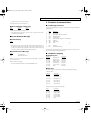
All exclusive communications are based on following structure ( Roland Exclusive
Format Type IV ).
*
a
b
c
d
e
[f
[g
[h
[i
[
j
k
These Mode Messages (2nd byte = 123-127) are also recognized as All Sounds
Off and Reset All Controllers.
■System Realtime Message
●Active Sensing
Status
FEH
*
When Active Sensing is received, the unit will begin monitoring the intervals of
all further messages. While monitoring, if the interval between messages
exceeds 300 ms, the same processing will be carried out as when All Notes Off
are received, and message interval monitoring will be halted.
●System Exclusive Message
Status
F0H
F7H
:System Exclusive
:EOX (End Of Exclusive)
Exclusive message can change either each parameter individually or all parameters, of a patch or tone.
Refer to Section 3 to see details.
*
Not received when the Exclusive Switch (SYSTEM MIDI) is OFF.
Byte
F0H
41H
dev
14H
xxH
aaH
bbH
ccH
ddH
:
sum
F7H
Description
Exclusive status
Roland ID #
Device-ID # = MIDI basic channel -1
Model-ID # (D-50)
Command-ID #
Address MSB ] [ ] depend on Command-ID
Address ]
Address LSB ]
Data
]
]
Checksum
EOX (End Of Exclusive)
Summed value of the all bytes between Command-ID and EOX (f-j) must be 00H (7
bits). It doesn’t include Command-ID and EOX.
■ 3.2 Address mapping
●Temporary area
Address
[00-00-00]
[00-00-40]
[00-01-00]
[00-01-40]
[00-02-00]
[00-02-40]
[00-03-00]
Upper Partial-1
Upper Partial-2
Upper Common
Lower Partial-1
Lower Partial-2
Lower Common
Patch
Description
temp-area
temp-area
temp-area
temp-area
temp-area
temp-area
temp-area
●Work area
You can transmit/receive data in the currently selected patch bank using the
following address.
Address
[02-00-00]
[02-03-40]
:
[03-5C-40]
[03-60-00]
[03-62-78]
:
[04-0C-08]
Description
Patch Memory 1-1
Patch Memory 1-2
:
Patch Memory 8-8
Reverb Data 17
Reverb Data 18
:
Reverb Data 32
Each patch memory consists of the followings.
Offset
[00-00-00]
[00-00-40]
[00-01-00]
[00-01-40]
[00-02-00]
[00-02-40]
[00-03-00]
Description
Upper Partial-1
Upper Partial-2
Upper Common
Lower Partial-1
Lower Partial-2
Lower Common
Patch
143