1
3.Installation
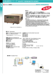
3-1 Installation of a wind direction & speed transmitter
1) In order to install a transmitter, select a position which is as far away as possible from
any obstacles so that natural draft can be measured without obstruction.
The transmitter is designed and produced so as to slightly turn in the wind. However, it can
not turn at all by itself. If the transmitter spins around, it has been installed in an inadequate
position.
2) We recommend you to install this device in a weak electric field which is away from the radio
antenna.
If this can not be avoided and the device is installed near the radio antenna, it may indicate
a digit for the automatically return to normal so do not mistaken it as breakdown.
3) Although the transmitter is designed to be vibration proof, it is advisable to install it in
a position in which there is as little vibration as possible in order to keep the transmitter
in good condition for a long time.
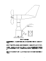
4) “N” is indicated on the flange of the transmitter. Therefore when installing the transmitter,
be sure to first confirm the position, then fasten the transmitter with screws. If the transmitter
is installed in an inadequate position, with direction is incorrectly indicated.
3-2 Installation of indicator
1) There are two holes 10Φ in diameter on the reverse side of the indicator. Therefore install
the indicator by putting screws or wood screws in the holes. The indicator is also provided
with a separate hole for an electric wire.
2) In order to open the inside of the indicator, remove the tow thumb screws on the upper part
of the front. However, take care not to remove any of the bolts of the hexagon socket head on
the lower part of the front.
3) When exchanging or removing the front panel to do the wiring of the indicator terminal, do
it in the following procedures:
(1) Turn the switch off.
(2) Remove connectors CN-3 and CN-4.
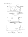
(3) Put your finger on the edge of the case as in Diagram 3 and while the thumb is pressing
the front panel in direction “A” pull the case and the front panel can be easily separated
from latch.
3-3 Wiring
As for wiring, refer to the attached connection diagram, and wire in the order indicated.
1) How to wire
In order to connect the transmitter and the indicator, use a MPYCS-7. For power supply, use
a 2-core cord 0.5mm2 or more in the sectional area.
2) The wiring distance between the transmitter and the indicator is limited to 1km or less.
3) The terminal number of the transmitter is the same as that of the indicator.
Therefore connect the same terminal numbers, connect the case earth to the frame ground.
4) In order to connect the indicator with plural apparatus, use 2-core shielded wires 0.5mm2 or
more in the sectional area.
7