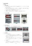
1
取扱説明書
Instruction Manual
3151
アースハイテスタ
EARTH HiTESTER
2013年7月 発行 改訂13版
July 2013 Revised edition 13 3151A980-13 13-07H
目次 1
――――――――――――――――――――――――――
目 次
はじめに
点検
安全について
ご使用にあたっての注意
1
1
2
5
第 1 章 概 要
1.1 製品概要
1.2 特長
1.3 各部の名称と機能
7
7
7
8
第 2 章 仕 様
2.1 一般仕様
2.2 測定範囲および許容差
2.3 動作不確かさ(EN61557-5 による)
11
11
13
14
第 3 章 解 説
3.1 接地抵抗
3.2 測定原理
15
15
16
第 4 章 測定方法
4.1 測定準備
4.2 3 電極法による測定方法
4.3 2 電極法(簡易測定)による測定方法
4.4 接地網の使用方法について
4.5 測定上の注意事項とポイント
19
19
20
25
30
31
第 5 章 保守・サービス
5.1 つりバンドの取付け
5.2 電池交換
5.3 本器のクリーニング
5.4 サービス
5.5 修理に出される前に
35
35
36
37
37
38
―――――――――――――――――――――――
目次 2
――――――――――――――――――――――――――
―――――――――――――――――――――――
1
――――――――――――――――――――――――――
はじめに
このたびは、HIOKI 3151 アースハイテスタ をご選定いただ
き、誠にありがとうございます。この製品を十分にご活用い
ただき、末長くご使用いただくためにも、取扱説明書はてい
ねいに扱い、いつもお手元に置いてご使用ください。
点検
本器がお手元に届きましたら、輸送中において異常または破
損がないか点検してからご使用ください。特に付属品および、
パネル面のスイッチ、端子類に注意してください。万一、破
損あるいは仕様どおり動作しない場合は、お買上店(代理店)
か最寄りの営業所にご連絡ください。
○ 付属品
9214 補助接地棒
2
9215 測定コード 1 式
1
( 黒 5 m・黄 10 m・赤 20 m、コード巻き(測定コードが
巻いてあります))
9393 携帯用ケース
1
つりバンド
1
取扱説明書
1
単 3 形マンガン乾電池(R6P)
6
―――――――――――――――――――――――
2
――――――――――――――――――――――――――
安全について
危険
この機器は IEC 61010 安全規格に従って、設計さ
れ、試験し、安全な状態で出荷されています。測定
方法を間違えると人身事故や機器の故障につなが
る可能性があります。また、本器をこの取扱説明書
の記載以外の方法で使用した場合は、本器が備え
ている安全確保のための機能が損なわれる可能性
があります。取扱説明書を熟読し、
十分に内容を理
解してから操作してください。万一事故があって
も、弊社製品が原因である場合以外は責任を負い
かねます。
○安全記号
この取扱説明書には本器を安全に操作し、安全な状態に保つ
のに要する情報や注意事項が記載されています。本器を使用
する前に次の安全に関する事項をよくお読みください。
・使用者は、機器上に表示されている
マークの
ところについて、取扱説明書の
マークの該当
箇所を参照し、機器の操作をしてください。
・使用者は、取扱説明書内の
マークのあるとこ
ろは、必ず読み注意する必要があることを示し
ます。
二重絶縁または強化絶縁で保護されている機器を
示します。
交流(AC)を示します。
―――――――――――――――――――――――
3
――――――――――――――――――――――――――
○取扱説明書の注意事項には、重要度に応じて以下の表記がさ
れています。
操作や取り扱いを誤ると、使用者が死亡または重
危険 傷につながる危険性が極めて高いことを意味しま
す。
操作や取り扱いを誤ると、使用者が死亡または重
警告 傷につながる可能性があることを意味します。
操作や取り扱いを誤ると、使用者が傷害を負う場
注意 合、または機器を損傷する可能性があることを意
味します。
製品性能および操作上でのアドバイスを意味しま
注記 す。
―――――――――――――――――――――――
4
――――――――――――――――――――――――――
○測定カテゴリについて
本器は CATⅡに適合しています。
測定器を安全に使用するため、IEC61010 では測定カテゴリ
として、使用する場所により安全レベルの基準を CATⅡ∼
CATⅣで分類しています。概要は次のようになります。
CATⅡ:コンセントに接続する電源コード付き機器(可搬形
工具・家庭用電気製品など)の一次側電路
コンセント差込口を直接測定する場合は CAT Ⅱで
す。
CATⅢ:直接分電盤から電気を取り込む機器(固定設備)の
一次側および分電盤からコンセントまでの電路
CATⅣ:建造物への引込み電路、引込み口から電力量メータ
および一次側電流保護装置(分電盤)までの電路
カテゴリの数値の小さいクラスの測定器で、数値の大きいク
ラスに該当する場所を測定すると重大な事故につながる恐れ
がありますので、絶対に避けてください。
カテゴリのない測定器で、CAT Ⅱ∼ CAT Ⅳの測定カテゴリ
を測定すると重大な事故につながる恐れがありますので、絶
対に避けてください。
―――――――――――――――――――――――
5
――――――――――――――――――――――――――
ご使用にあたっての注意
●本器を安全にご使用いただくために、また機能を十二分にご
活用いただくために、次の注意事項をお守りください。
危険
・接地抵抗測定時には、測定端子 E−C (H) 間に最
大 AC50 Vrms の電圧が発生します。感電しない
ように十分注意してください。
・商用電源のアース側に接続し簡易測定(2 電極
法)を行う場合には、感電事故のないように十分
注意してください。
警告
・本器をぬらしたり、ぬれた手で測定しないでく
ださい。感電事故の原因になります。屋外での
使用時には十分に注意してください。
・腐食性ガスや爆発性ガスが発生する場所では使
用しないでください。本器の破損もしくは、
爆発
事故を誘発する可能性があります。
・電池以外の電源は使用しないでください。本器
の破損や感電事故の原因となります。
・測定コードの被覆が破れたり、金属が露出して
いないか、
使用する前に確認してください。損傷
がある場合は、
感電事故になるので、
指定の 9215
測定コードと交換してください。
―――――――――――――――――――――――
6
――――――――――――――――――――――――――
注意
・直射日光や高温、多湿、結露するような環境下で
の、保存や使用はしないでください。変形、絶縁
劣化を起こし、仕様を満足しなくなります。
・本器は簡易防じん構造となっていますが、内部
へのホコリや水滴の侵入を完全に防ぐものでは
ありません。故障の原因になりますので、
注意し
てください。
・本器の損傷を防ぐため、運搬および取り扱いの
際は振動、衝撃を避けてください。特に、落下な
どによる衝撃に注意してください。
―――――――――――――――――――――――
7
――――――――――――――――――――――――――
第 1 章 概 要
1.1 製品概要
電気設備に施される接地工事は、人体および機器の保安のた
めにきわめて重要です。
本器では、接地抵抗測定に交流電位差計方式を採用している
ため、地電圧や補助接地抵抗による影響が少なく正確な測定
が行えます。
1.2 特長
(1) 高性能
本器は J ISC-1304-1995 規格を上まわる性能と
IEC 61010 安全規格に従った安全設計です。
(2) 測定範囲を拡大
接地抵抗測定範囲を測定レンジの 115%に拡大しています。
接地工事の判定基準となる 10 Ω/ 100 Ω付近の抵抗判定に
便利です。
(3) 補助接地抵抗チェック機能内蔵
測定誤差の要因となる補助接地抵抗の大きさを補助接地極
ごとに確認できます。
(4) 測定周波数の切替機能内蔵
測定周波数を切り替えることにより、高調波地電圧などの
影響を軽減して安定した測定ができます。
―――――――――――――――――――――――
第 1 章 概 要
8
――――――――――――――――――――――――――
(5) 簡易測定機能内蔵
商用電源のアース側など低接地体を利用して簡単に接地抵
抗が測定できます。
(6) 過電圧保護と警告ブザー機能内蔵
簡易測定の商用電源利用時に、誤接続により電圧を入力し
た場合、回路を保護するとともにブザーにより誤接続を警
告します。
(7) 簡易防じん仕様
測定スイッチや抵抗ダイヤルなどの可動部周辺の防じん性
をアップさせ、ハードな現場測定に応えます。
(8) 取り扱いが便利
本体・付属品を一括収納できる携帯用ケースを採用し、測
定コードの配線、後片付けに便利なコード巻が標準付属に
なりました。
1.3 各部の名称と機能
11
12
14
13
10
4
5
6
7
8
9
1
2
3
―――――――――――――――――――――――
第 1 章 概 要
9
――――――――――――――――――――――――――
1
測定スイッチ(PRESS ON)
接地抵抗測定および補助接地抵抗チェック、バッテリチェック
のときに押します。
2
レンジ切替スイッチ
バッテリチェック、地電圧測定、補助接地抵抗チェック、接地
抵抗測定を切り替えます。
3
2/3 電極法切替スイッチ(TERMINALS)
2 電極法(簡易測定)と 3 電極法を切り替えます。また、高調波
地電圧などの影響を軽減するために測定周波数(a/b)が選択で
きます。
4
抵抗ダイヤル
測定した抵抗値を読み取ります。
5
ダイヤルツマミ 6
検流計
7
電池有効範囲 8
補助接地抵抗有効範囲 9
地電圧目盛 10 ADJUST:零位調整器
11
E:接地電極端子
被測定接地体を接続する端子です。
12
P(S)
:プローブ端子
測定中の電位を検出する端子です。
13
C(H)
:補助接地電極端子
測定電流を供給する端子です。
14
指示ワッペン
簡易取扱説明、製品仕様を表示します。
―――――――――――――――――――――――
第 1 章 概 要
10
――――――――――――――――――――――――――
16
15
15
電池カバーの留めネジ
16
電池カバー
―――――――――――――――――――――――
第 1 章 概 要
11
――――――――――――――――――――――――――
第 2 章 仕 様
2.1 一般仕様
動作方式
交流電位差方式
表示方法
等分目盛ダイヤル抵抗値表示、メータ式
検流計
開放回路電圧
AC50 V max
測定電流
AC15 mA max(2電極法使用時:AC3 mA max)
測定周波数
575 Hz(2aまたは3aに設定時)
600 Hz(2bまたは3bに設定時)
使用温湿度範囲
0℃∼40℃、80% rh以下(結露しないこと)
保存温湿度範囲
-10℃∼50℃、80% rh以下
(結露しないこと)
使用場所
(適用範囲)
高度3000 m以下、汚染度2
農場を除くその他の接地抵抗測定(注)
電源
単3形マンガン乾電池(R6P×6)または
単3形アルカリ乾電池(LR6×6)
定格電源電圧:1.5 V×6
最大定格電力
2.5 VA
(注)接地抵抗計に関する国際規格(EN61557-5)の規定によ
る制限
―――――――――――――――――――――――
第 2 章 仕 様
12
――――――――――――――――――――――――――
使用回数
約 350回(R6P使用時)
約 1100回(LR6使用時)
(30秒測定/30秒休止)
過電圧保護
AC250 V 1分間
(E−P(S)、E−C(H)端子間)
耐電圧
AC3000 V 1分間
対地間最大定格
電圧
AC30 V、測定カテゴリⅡ
(予想される過渡過電圧500 V)
外形寸法
約164W×119H×88D mm
(支持足等の突起含まず)
質量
約800 g(本体のみ)
付属品
9214 補助接地棒 ×2
9215 測定コード
(黒5 m,黄10 m,赤20 m 各1、
コード巻 ×3)
9393 携帯用ケース
つりバンド
単3形マンガン乾電池(R6P) ×6
取扱説明書
オプション
9050 接地網 30×30 cm
適合規格
接地抵抗計;JIS C1304-1995
;EN61010
安全性
EMC ;EN61326
IP保護等級
IP40
確度保証期間
1年間
製品保証期間
3年間
電気回路と筐体間
―――――――――――――――――――――――
第 2 章 仕 様
13
――――――――――――――――――――――――――
2.2 測定範囲および許容差
測定レンジおよび許容差
(温湿度:23℃±5℃、80% rh 以下において 1 年間保証)
測定項目
レンジ切替
スイッチ
測定レンジ
(測定範囲)
許容差
×1 Ω
10 Ω(0∼11.5 Ω)
±2.5%f.s.
×10 Ω
100 Ω(0∼115 Ω)
±2.5%f.s.
接地抵抗
×100 Ω
地 電 圧
∼V
1000 Ω(0∼1150 Ω) ±2.5%f.s.
30 V(0∼30 V)
±3.0%f.s.
、
2 極法の場合、測定レンジ(測定範囲)が 100 Ω(0∼115 Ω)
1000 Ω(0∼1150 Ω)のみ適用
温度の影響
0℃∼40℃において±0.1%/℃以内
補助接地抵抗の
影響
0∼5 kΩの変化において±5%以内
地電圧の影響
0∼5 Vにおいて±2%以内
0∼10 Vにおいて±5%以内
(50、60 Hzにて)
0∼3 Vにおいて±5%以内
(DC、16 2/3Hz、400 Hzにて)
電源電圧の影響
DC6∼10 Vにおいて仕様許容差内
―――――――――――――――――――――――
第 2 章 仕 様
14
――――――――――――――――――――――――――
2.3 動作不確かさ(EN61557-5 による)
動作不確かさは、その動作範囲内における影響量の値の組合
せです。算定式は次の通りです。
動作不確かさ
固有誤差
または
影響量
標準状態
または
規定の動作範囲
分類 EN61557の関係する
コード
部に従った
要求事項または試験
誤差
固有誤差
標準状態
A
Part5, 6.1
±2.5%
位置
標準位置±90
E1
Part1, 4.2
±5.0%
供給電圧
製造者が示した
限度値において
E2
Part1, 4.2, 4.3
±0.0%
温度
0℃および35℃
E3
Part1, 4.2
±2.3%
地電圧
4.2項および4.3項
E4
Part5, 4.2, 4.3
±5.0%
補助接地
抵抗
0から100×RA
ただし≦50 kΩ
PCチェック確認
による
E5
Part5, 4.3
±5.0%
システム
周波数
定格周波数の
99%から101%
E7
Part5, 4.3
−
システム
電圧
定格電圧の
85%から110%
E8
Part5, 4.3
−
B
Part5, 4.3
±12.8%
動作
不確かさ
*RA:全接地抵抗(主接地端子と大地との間の抵抗)
―――――――――――――――――――――――
第 2 章 仕 様
15
――――――――――――――――――――――――――
第 3 章 解 説
3.1 接地抵抗
接地抵抗は、通常の抵抗測定と異なり下記のような特殊性が
あります。
(1) 分極作用
接地体と大地間に分極作用が存在するため、直流で測定す
ることができません。
(2) 特殊な形態
接地抵抗は、片端子が地中に埋まっているため端子を取り
出すことができません。
また、接地抵抗は、接地体からのひろがり抵抗的なもので
あるため測定電極の間隔を長くとった 3 電極法によって測
定する必要があります。
(3) 外乱要素の存在
ろうえい
接地抵抗の測定には、接続された機器からの漏洩電流およ
び地電流による地電圧や補助接地極の影響などの外乱要素
が存在します。
上記接地抵抗の特殊性を考慮して、本器では交流電位差計
方式を採用するとともに独自の回路技術により地電圧の影
響を受けないように配慮してあるため、悪条件下でも正確
な測定ができます。
―――――――――――――――――――――――
第 3 章 解 説
16
――――――――――――――――――――――――――
3.2 測定原理
(1) 3 電極法(精密測定)
図 1 に接地抵抗計の測定原理図を示します。
発振器の発振電圧によって駆動された測定電流 I は、発振
器→Rc→Rx→C.T.によって形成されるループを流れます。
今、検流計がバランスした場合には、測定端子 E−P(S)
間に生じる電圧を Ex、
測定端子 E としゅう動抵抗器のしゅ
う動子 S 間の抵抗を Rs その電圧降下を Es としますと、
Ex=IRx, Es=IRs/n(n:C.T.の巻線比)
Ex=Es より Rx=Rs/n となります。
したがって、
しゅう動抵抗器に直結したダイヤルに Rs に対
して 1/n の目盛を設定すれば、
ダイヤル上の読み値が求め
る接地抵抗(Rx)となります。
C.T.
1:n
検流計
I
発振器
S
同期整流器
Rs
E
Rx
P(S)
C(H)
Rp
Rc
図1 測定原理図(3 電極法)
―――――――――――――――――――――――
第 3 章 解 説
17
――――――――――――――――――――――――――
(2) 2 電極法(簡易測定)
既設の接地体を利用する、2 電極法による簡易測定の場合
の測定原理図を図 2 に示します。
今、既設の接地体の接地抵抗を Ro、被測定接地抵抗を Rx
としますと、3 電極法と同様にして
Rx+Ro=Rs/n となります。
したがって、既設の接地抵抗(Ro)と被測定接地抵抗(Rx)
の和として求めることができます。
また、既設の接地抵抗体として商用電源のアース側を利用
する場合にも、測定電流を小さく設定してあり漏電ブレー
カが動作しないように配慮してあります。
C.T.
1:n
検流計
I
発振器
S
同期整流器
Rs
E
P(S)
Rx
C(H)
Ro
図2 測定原理図(2 電極法)
―――――――――――――――――――――――
第 3 章 解 説
18
――――――――――――――――――――――――――
―――――――――――――――――――――――
第 3 章 解 説
19
――――――――――――――――――――――――――
第 4 章 測定方法
危険
・測定スイッチ(PRESS ON)を押しますと、測定端
子に AC50 V max の電圧が発生します。感電しな
いように充分注意してください。
・簡易測定に商用電源のアース側を利用する場合に
は、接続前に必ず検電器などでアース側を確認し
てから接続し、 感電事故には注意してください。
注意
・電池が消耗している場合には、誤接続により電圧
が入力されても警告ブザーは鳴りません。使用
前には必ずバッテリチェックを行ってください。
・補助接地棒をハンマーで打ち込む場合、T字の端
の部分をたたくと補助接地棒が破損します。
T字の中心をたたいてください。
4.1 測定準備
(1) 使用前に検流計の指針の零位調整をしてください。マイ
ナスドライバーなどで零位調整器(ADJUST)を回し、指
針を▼目盛の中央に合わせます。測定スイッチ(PRESS
ON)は押さない状態で行います。
電池が消耗していない
(2) 使用前にバッテリチェックを行い、
か確認してください。消耗している場合には新しい電池と
交換してください。
(「5.2 電池交換」を参照)
注記 補助接地棒に先端保護チューブがついている場合は、チ
ューブを外してから使用してください。
―――――――――――――――――――――――
第 4 章 測定方法
20
――――――――――――――――――――――――――
4.2 3 電極法による測定方法
(1) 接続方法図 3 に示すように、
付属の測定コードを本器の測
定端子にそれぞれ接続します。補助接地棒 P、補助接地棒
C を被測定接地体 E より 5∼10 m の間隔で一直線上になる
ように地中に深く打ち込み、測定コードを接続します。
測定端子
測定コード
接続
E
P(S)
C(H)
黒コード
黄コード
赤コード
被測定接地体 E
補助接地棒 P
補助接地棒 C
C
P
E
E
P
C
Rx
5∼10 m
5∼10 m
図 3 3 電極法による測定での接続
注記
・補助接地棒は、なるべく湿気の多い地面に差し込むように
してください。堅い地面やコンクリートなど補助接地棒を
差し込めない場合には、
オプションの 9050 接地網を使用し
てください。
(「4.4 接地網の使用方法」を参照)
―――――――――――――――――――――――
第 4 章 測定方法
21
――――――――――――――――――――――――――
・補助接地棒をハンマーで打ち込む場合、T字の端の部分を
たたくと補助接地棒が破損します。
T字の中心をたたいてください。
ハンマーで打ち込む場合、
T 字の中心部分をたたいてください。
(2) 3 電極法の設定
2 / 3 電 極 法 切 替 ス イ ッ チ
(TERMINALS)
を 3a に設定します。
注記 3 電極法使用時には、3a(575 Hz)と 3b(600 Hz)の 2
通りの測定周波数で測定ができます。通常は 3a に設定
します。測定中に検流計の指針がふらつき安定しない場
合には、3b に切り替えて測定します。測定周波数を変え
ることにより高調波地電圧などの影響を受けづらくなり
ます。
(3) バッテリチェック
レンジ切替スイッチを
に設
定し、測定スイッチ(PRESS ON)
を押して、検流計の指針が
マークの帯内にあることを確認し
ます。確認は各端子が接続された
測定状態で行ってください。
注記 指針が帯内まで振れない場合には、新しい電池に交換し
てください。
(
「5.2 電池交換」を参照)
―――――――――――――――――――――――
第 4 章 測定方法
22
――――――――――――――――――――――――――
(4) 地電圧チェック
レ ン ジ 切 替 スイッチを
V に設
定し、地電圧の有無を確認します。
このとき、測定スイッチは押さな
いでください。
注意
・測定スイッチを押すと、地電圧測定ができませ
ん。また、検流計の指針が振れたり、振り切れる
場合がありますが故障ではありません。
・地電圧が 10 V 以上ある場合には、接地体を電気
設備から切り離すか、電路のスイッチを切って
地電圧がなるべく小さい状態で測定してくださ
い。また、
地電圧が高い場合には感電の危険性が
ありますので充分注意してください。
(5) 補助接地抵抗チェック
補助接地棒の接地状態をチェックする機能です。接地抵抗
測定前に必ず確認してください。
判定は、検流計の指針が左側に振れるほど補助接地抵抗値
が高いことを示します。(指針は零位から振れないほど補
助接地抵抗が良好)
① 補助接地棒 C の接地状態の確認
レンジ切替スイッチを C に設定
し、測定スイッチ(PRESS ON)
を押します。
検流計の指針が P/C CHECK マー
クの緑色の帯内に入っていること
を確認します。
―――――――――――――――――――――――
第 4 章 測定方法
23
――――――――――――――――――――――――――
② 補助接地棒 P の接地状態の確認
レンジ切替スイッチを P に設定
し、測定スイッチ(PRESS ON)
を押します。
検流計の指針が P/C CHECK マー
クの緑色の帯内に入っていること
を確認します。
注記
・補助接地棒 C と P 両方の接地状態を確認してください。
・指針が緑色の帯内に入らない場合には、補助接地棒の接地
抵抗が大きく、正確な測定ができません。対策として、補
助接地棒をなるべく湿気の多い地面に打ち込むなど打ち込
み位置を変えたり、補助接地棒の回りに充分に水をかけて
再度確認してください。
・2/3 電極法切替スイッチを 2 電極側(2a/2b)に設定してあ
ると、正しいチェックができません。
(6) 接地抵抗測定
レンジ切替スイッチを×1 Ω、×10 Ω、×100 Ωの中から
適当な抵抗レンジに設定し、測定スイッチ(PRESS ON)
を押しながらダイヤルツマミを回して、検流計の指針を▼
マークに合わせます。
抵抗ダイヤルの読み値にレンジの倍率を掛けた値が求める
測定値になります。
―――――――――――――――――――――――
第 4 章 測定方法
24
――――――――――――――――――――――――――
注記
・レンジの設定は原則として、まず×100 Ωレンジで測定し
必要に応じてレンジを下げて測定してください。
・2/3 電極法切替スイッチを 2 電極側(2a/2b)に設定してあ
ると正しい測定値が得られません。
・14 ページの 2.3 動作不確かさの項に記載のように、本器は
各影響量に対して誤差を生じます。固有誤差と各影響量に
対する誤差の合計は±19.8%f.s.になります。これは測定条
件により最大で±19.8%f.s.(×1 Ωレンジの場合:±1.98
Ω)の誤差を生じることを示しています。この誤差のため、
×1 Ωレンジで接地抵抗が約 2 Ω以下の場合、抵抗ダイヤ
ルの 0 目盛よりも右側(負側)で検流計のバランスがとれ
ることがあります。この場合は、接地抵抗は 2 Ω以下と判
断してください。
ただし、抵抗ダイヤルの 0 目盛よりも右側の範囲で、検流
計の指針が抵抗ダイヤルに連動して動かないときは、測定
は無効です。
・メッシュ接地極、環状接地極、大型建築物の構造体による
接地極などの大規模接地極の測定では、E 極の接地抵抗区
域内に C 電極、P 電極が入ってしまうため、正確に測定で
きません。C 電極、P 電極が接地抵抗区域内に入らないよう
に長い測定コードを使用するとノイズの影響を大きく受け
てしまい、正確な測定ができません。
一般的に大規模接地極の測定には 20 A 程度の大きな測定
電流が必要ですので、大規模接地極測定用の専用測定器で
測定してください(専用測定器は弊社にはありません)
。
―――――――――――――――――――――――
第 4 章 測定方法
25
――――――――――――――――――――――――――
4.3 2 電極法(簡易測定)による測定方法
危険
簡易測定に商用電源のアース側を利用する場合に
は、接続前に必ず検電器などでアース側を確認し
てから接続し、感電事故には注意してください。
なお、誤って活電部に接続し 85 V 以上の電圧が入
力されますと警告ブザーが「ピー」と鳴ります。警
告ブザーが鳴った場合には、ただちに接続を外し
アース側を再度確認し接続してください。
警告
接続するときには E 端子を最初に接続してくださ
い。E 端子が接地体に接続されていないと警告ブ
ザーは鳴りません。漏電ブレーカを備えた電源ラ
インで誤った接続をした場合、警告ブザーが鳴る
前にブレーカが動作する場合があります。
簡易測定法(2 電極法)とは、補助接地棒を打ち込めない場合
に、補助電極として既設の低接地抵抗体を利用して接地抵抗
を求める方法です。
測定に際しては、被測定接地体よりも充分抵抗値の低い既設
の接地抵抗体を補助電極として用いてください。
なお、2 電極法に設定すると測定電流を 3 mA 以下に抑えるた
め、商用電源のアース側に接続し測定した場合でも漏電ブレ
ーカを動作させません。
注記 簡易測定法では利用する接地体の抵抗値が測定結果に加
算されます。
10 Ω以下の測定は、必ず 3 電極法で行ってください。
―――――――――――――――――――――――
第 4 章 測定方法
26
――――――――――――――――――――――――――
(1) 接続方法
図 4 に商用電源のアース側を利用した接続方法を示しま
す。付属の測定コードを本器の測定端子にそれぞれ接続し
ます。
、または
レンジ切替スイッチを
V に設定し、E 端
子を被測定接地体 E に接続してから、C(H)端子を商用電
源の接地線に接続します。
P
測定端子
測定コード
接続
E
P(S)
C(H)
黒コード
被測定接地体 E
接続しない
接地線(Ro)
赤か黄コード
S
AC250 V max
E
C
Rx
Ro
5 m以上
図 4 簡易測定での接続
注記 補助接地体に用いる低接地抵抗体としては A 種接地体
(旧第 1 種接地)
や金属製水道管などの金属製埋設物が利
用できます。
また、補助接地体に用いる低接地抵抗体は、被測定接地
体から 5 m 以上離してください。近接していると正確な
測定ができません。
―――――――――――――――――――――――
第 4 章 測定方法
27
――――――――――――――――――――――――――
(2) 2 電極法の設定
2/3 電極法切替スイッチ
(TERMINALS)を 2a に設定しま
す。
注記 2 電極法使用時には、2a(575 Hz)と 2b(600 Hz)の 2
通りの測定周波数で測定ができます。通常は 2a に設定
します。測定中に検流計の指針がふらつき安定しない場
合には、2b に切り替えて測定します。測定周波数を変え
ることにより、高調波地電圧などの影響を受けづらくな
ります。
(3) バッテリチェック
レンジ切替スイッチを
に
設定し、測定スイッチ(PRESS
ON)を押して、検流計の指針が
マークの帯内にあること
を確認します。確認は各端子が接
続された測定状態で行ってくださ
い。
注記 指針が帯内まで振れない場合には、新しい電池に交換し
てください。
(
「5.2 電池交換」を参照)
(4) 地電圧のチェック
レ ン ジ 切 替 スイッチを
V に設
定し、地電圧の有無を確認します。
このとき、測定スイッチは押さな
いでください。
―――――――――――――――――――――――
第 4 章 測定方法
28
――――――――――――――――――――――――――
注意
・測定スイッチを押しますと、地電圧測定ができ
ません。また、検流計の指針が振れたり、振り切
れる場合がありますが故障ではありません。
・地電圧が 10 V 以上ある場合には、接地体を電気
設備から切り離すか、電路のスイッチを切って
地電圧がなるべく小さい状態で測定してくださ
い。また、
地電圧が高い場合には感電の危険性が
ありますので充分注意してください。
(5) 補助接地抵抗チェック
補助接地抵抗の確認は不要です。
注記 レンジ切替スイッチを P または C に設定し、測定スイッ
チを押しますと検流計の指針が振れたり振り切れる場合
がありますが故障ではありません。また、チェック動作
は無効です。
(6) 接地抵抗測定
レンジ切替スイッチをを×10 Ω、×100 Ωのいずれか適当
な抵抗レンジに設定し(×1 Ωは確度保証外です)
、測定ス
イッチ(PRESS ON)を押しながらダイヤルツマミを回し
て、検流計の指針を▼マークに合わせます。
抵抗ダイヤルの読み値にレンジの倍率を掛けた値が求める
測定値になります。
測定値 = Rx+Ro の合成抵抗値となります。
―――――――――――――――――――――――
第 4 章 測定方法
29
――――――――――――――――――――――――――
注記
・レンジの設定は原則として、まず×100 Ωレンジで測定し
必要に応じてレンジを下げて測定してください。
・2/3 電極法切替スイッチを 3 電極側(3a/3b)に設定してあ
ると測定できません。また、
3 電極側に設定してあると測定
電流が大きいため漏電ブレーカなどが動作することがあり
ます。
・抵抗ダイヤル目盛のないところで検流計の指針が▼マーク
に合った場合、この測定結果は無効となります。
―――――――――――――――――――――――
第 4 章 測定方法
30
――――――――――――――――――――――――――
4.4 接地網の使用方法について
地面が岩石や砂利またはコンクリートのように堅くて、補助
接地棒の打込みが困難な場合に接地網を使用してください。
なるべく地面に密着するように敷いて充分水を
(1) 接地網は、
かけます。水が地面に充分浸透するのを待ちます。
(2) 測定コードとの接続は図のように接地網に直接クリップ
するか補助接地棒を接地網の上に置いてください。
(3) レンジ切替スイッチを P、C レンジに設定して、接地網の
接触状態を、必ず確認してから測定を行ってください。
注記 ・アスファルト舗装など水の浸透性がきわめて悪い場所では、
接地網による測定はできません。
(ただし、
浸透性のあるア
スファルトであれば接地網による測定は可能)
・接地網が無い場合や小さい場合には、代用として金属板な
どの導電性材料を地面に敷いて充分水をかけて測定してく
ださい。
―――――――――――――――――――――――
第 4 章 測定方法
31
――――――――――――――――――――――――――
4.5 測定上の注意事項とポイント
■ 補助接地棒の使用方法について
3 電極法の測定には、2 本の補助接地棒が必要です。補助接
地棒の打込みが悪いと正確な測定ができない場合がありま
す。
■ 補助接地棒の接地抵抗について
本器では補助接地棒の接地抵抗が 10 kΩ程度まで測定に
支障がないように配慮してありますが、特に A 種(旧第 1
種)接地工事のように低い接地抵抗を測定する場合、補助
接地棒の接地抵抗が大きいと測定感度が不十分なことがあ
ります。
正確な測定をするために、レンジ切替スイッチを C および
P レンジに設定し、補助接地棒の各接地状態を必ずチェッ
クしてください。メータ内の緑色の帯内にあれば補助接地
抵抗は 5 kΩ以内です。
チェックした結果で外れた場合
① 補助接地棒を充分地中深く打ち込み周辺に充分水をま
きます。特に、十分な水まきは地面との接触抵抗を下げ
るのに効果的です。
② 打込場所を変えます。できるだけ湿気の多い地面を探し
て打ち込んでください。
また、地面が火山岩や砂地の場合には、付属の補助接地棒
では十分な補助接地抵抗が得られない場合があります。こ
のような場合には、金属製パイプなど、導電性で地面との
接触面積が広く取れる物を用意し、できるだけ深くまで打
ち込んでください。
―――――――――――――――――――――――
第 4 章 測定方法
32
――――――――――――――――――――――――――
■ 接地電極間距離について
図 5(a)に示すように E−C 間距離を l m とし、E−P 電
極間の距離 x m を変えて接地体 E の抵抗値を測定すると図
5(b)に示すような測定結果が得られます。
したがって、補助接地棒 P の位置が接地体 E あるいは補助
接地棒 C に近くなると誤差を生じます。
また、E−C 電極間距離が短いと被測定接地抵抗(Rx)と補
助接地棒の接地抵抗(Rc)とが分離できなくなり、測定誤
差を生じます。
建築構造体など大きな面積で接地されている場合、図 5(a)
で示す接地抵抗(Rx)の抵抗区域が非常に広くなります。
正確な測定をするためには接地体(Rx)から十分離れた場
所に補助接地棒(P および C)を打ち込む必要があります。
確認方法としては、測定時に補助接地棒 P の位置を接地体
(Rx)から補助接地棒 C 側に移動して数箇所測定し、図 5
(b)に示す補助接地棒 P を移動しても測定抵抗値がほぼ一
定な水平部が発生するかを確認します。
もし、水平部ができない場合には、測定距離が不足してい
ますので補助接地棒(P および C)の打ち込み位置を遠くに
移動してください。
lm
(b)
xm
E
P
C
地表面
測定値
(a)
水平部
Rc
Rx
E 電極の
抵抗区域
C 電極の
抵抗区域
xm
lm
図 5 接地電極間距離について
―――――――――――――――――――――――
第 4 章 測定方法
33
――――――――――――――――――――――――――
■ 補助接地棒の位置関係について
補助接地棒 P は、
接地体 E と補助接地棒 C とを結ぶ直線上
の中央に打ち込むことが理想です。
しかし、障害物などがあって打ち込めない場合には、図 6
に示すように接地体 E、補助接地棒 C より半径 5 m 以内の
領域を避けて、接地体 E から補助接地棒 C を結ぶ直線より
29°以内に補助接地棒 P を打ち込ことにより測定誤差を
軽減できます。
E
5m
P
C
29
5m
図 6 補助接地棒の位置関係について
■ 地電圧の影響について
接地体に接続された電気機器からの漏洩電流または地電流
により、接地体に電圧が存在する場合があります。
接地抵抗測定には、10 V 程度まで支障ありませんが地電圧
が歪んでいる場合には、10 V 以下でも測定誤差を生ずるこ
とがあります。したがって、通常は地電圧が 5 V 以上ある
場合には、電気機器の運転を停止するか電気機器を接地体
から切り離して地電圧の影響のない状態で測定してくださ
い。
また、簡易測定法使用時では接地線に高調波漏れ電流など
が含まれている場合に、検流計の指針がふらつき、安定し
ない場合があります。このような場合には、2/3 電極法切
替スイッチを 2a から 2b へ(3 電極法による測定の場合は
3a から 3b)切り替えると安定した測定ができます。
ろ う え い
ひ ず
―――――――――――――――――――――――
第 4 章 測定方法
34
――――――――――――――――――――――――――
なお、地電圧が高い場合には、電路または電気機器の絶縁
劣化の可能性が考えられます。絶縁および漏洩電流試験も
合わせて行なう必要があります。
ろ う え い
―――――――――――――――――――――――
第 4 章 測定方法
35
――――――――――――――――――――――――――
第 5 章 保守・サービス
5.1 つりバンドの取付け
本体に付属のつりバンドを取り付けますと、携帯用ケースか
らの取出し、持運びに便利です。
―――――――――――――――――――――――
第 5 章 保守・サービス
36
――――――――――――――――――――――――――
5.2 電池交換
警告
・感電事故を避けるため、測定コードを被測定物
より外してから電池を交換してください。交換
後は、必ずカバーをしてネジを留めてから使用
してください。
・電池をショート、充電、分解または火中への投入
はしないでください。破裂する恐れがあり危険
です。
・電池は地域で定められた規則に従って処分して
ください。
注記・電池の液漏れによる腐食を防ぐため、長い間使用しない
ときは、電池を抜いて保管してください。
・電池は単 3 形マンガン乾電池または単 3 形アルカリ乾電
池を使用してください。ニッケル水素電池、ニッカド電
池、オキシライド電池などは使用しないでください。
A
留めネジ
B
(1)
(2)
(3)
(4)
(5)
(6)
測定コードを安全のため本体から外します。
留めネジを外します。
電池カバーを図の A 方向に外します。
電池 6 本を全部交換します。
電池カバーを B 方向から取り付けます。
電池カバーを本体にネジ留めします。
―――――――――――――――――――――――
第 5 章 保守・サービス
37
――――――――――――――――――――――――――
5.3 本器のクリーニング
・補助接地棒は、使用後に泥などを拭き取ってください。そ
のまま放置しますとさびの原因になります。
・本器の汚れをとるときは、柔らかい布に水か中性洗剤を少
量含ませて、軽く拭いてください。ベンジン、アルコール、
アセトン、エーテル、ケトン、シンナー、ガソリン系を含
む洗剤は絶対に使用しないでください。変形、変色するこ
とがあります。
5.4 サービス
・故障と思われるときは、電池の消耗、測定コードの断線 を
確認してから、お買上店(代理店)か最寄りの営業所にご
連絡ください。
・輸送中に破損しないように梱包し、故障内容も書き添えて
ください。輸送中の破損については保証しかねます。
―――――――――――――――――――――――
第 5 章 保守・サービス
38
――――――――――――――――――――――――――
5.5 修理に出される前に
症状
確認内容
測定端子に接地極を接続せ
ずに測定スイッチを押すと
検流計の指針が振れたり、
振り切れたりする。
故障ではありません。
測定スイッチを押すと、内
部から微かに発信音が聞こ
える。
故障ではありません。
抵抗ダイヤルを回しても検
流計の指針が 0 よりも左側
しか指さない。
接地抵抗が測定範囲よりも大
きいためです。
→接地極の接地状態を確認し
てください。
検流計の指針が左側に振り
きれる。
測定コードの断線、または、
接地線が大地に接続されてい
ないためです。
→テスタの導通レンジで測定
コードの断線の有無を確認し
てください。
検流計の指針がふらつく。
大きな電圧が発生している、
補助接地棒の接地抵抗が高い
可能性があります。
→地電圧と補助接地抵抗のチ
ェックをしてください。
アスファルト上に接地網を
敷いて測定しようとしたが
測定できない。
アスファルトは絶縁物である
ため、接地網を使用しても測
定できません。
―――――――――――――――――――――――
第 5 章 保守・サービス
39
――――――――――――――――――――――――――
症状
確認内容
P チェック、C チェックで
補助接地極の接地抵抗が高い
緑色の帯に指針が入らない。 ためです。
→接地棒を違う場所に打ち直
す、または、補助接地棒に水
を掛けてください。
本器の E 端子、C 端子、P
端子を短絡して測定すると
測定値が 0 Ωになる。
本器は故障しておりません。
→測定コードの断線、接地極
の接地状態を再確認してくだ
さい。
新築住宅で測定しているが、 電力会社から電気が配電され
2 電極法で測定できない。
ていない状態では測定できま
せん。
2 電極法で測定したが、測
定値が想定している抵抗値
よりも大きい。
本器は、2 電極法で使用する
場合、×1 Ωレンジの確度は
保証していません。よって、
本器の 2 電極法では 10 Ω以
下の低い接地抵抗を正確に測
定できません。
既設の測定用補助極を使っ
て測定しているが、測定値
が 0 Ωになる。
接地極と測定用補助極がコン
クリートなどで接続されてい
る可能性があります。
→測定用補助極を使用せず、
補助接地棒を大地に打ち込み
測定してください。
新品の電池を入れて、電池
電圧チェックをおこなって
も指針が動かない。
故障です。
→修理に出してください。
―――――――――――――――――――――――
第 5 章 保守・サービス
40
――――――――――――――――――――――――――
付録
接地工事の種類と接地抵抗値
電気設備技術基準では、次のように接地工事の種類と接地抵
抗値が定められています。
接地工事の種類
接地抵抗値
A 種(第 1 種)
接地工事
10Ω以下
B 種(第 2 種)
接地工事
計算値
(注 1)
C 種(特別第 3 種)
接地工事
10Ω以下
(注 2)
D 種(第 3 種)
接地工事
100Ω以下
(注 2)
(注 1)変圧器の高圧側又は特別高圧側の電路の一線地絡電流
のアンペア数で 150 ( 変圧器の高圧側の電路又は使用
電圧が 35000V 以下の特別高圧側の電路と低圧側の電
路との混触により低圧電路の対地電圧が 150V を超え
た場合に、1 秒を超え 2 秒以内に自動的に高圧電路又は
使用電圧が 35000V 以下の特別高圧電路を遮断する装
置を設けるときは 300、1 秒以内に自動的に高圧電路又
は使用電圧が 35000V 以下の特別高圧電路を遮断する
装置を設けるときは 600)を除した値に等しいオーム数
(注 2)低圧電路において、当該電路に地気を生じた場合に 0.5
秒以内に自動的に電路を遮断する装置を施設するとき
は、500Ω
―――――――――――――――――――――――
3151
3151
EARTH HiTESTER
Instruction Manual
Contents
Introduction
Inspection
Safety Notes
Notes on Use
i
i
ii
vi
Chapter 1 Outline
1
1.1 Product Outline
1.2 Features
1.3 Names and Functions of Parts
Chapter 2 Specifications
2.1 General Specifications
2.2 Measurement Range and Tolerances
Chapter 3 Technical Information
3.1 Earthing Resistance
3.2 Measurement Principle
Chapter 4 Measurement Procedure
4.1 Preparations
4.2 3-Pole Measurement Method
4.3 2-Pole Measurement Method
(Simplified Measurement)
4.4 Using the Earthing Net
4.5 Measurement Precautions and Hints
1
2
4
7
7
9
11
11
13
15
16
17
23
30
31
Chapter 5 Maintenance and Service
5.1
5.2
5.3
5.4
5.5
Attaching the Hand Strap
Changing the Batteries
Cleaning the Unit
Service
Before returning for repair
37
37
38
40
40
41
i
―――――――――――――――――――――――――――
Introduction
Thank you for purchasing the HIOKI 3151
EARTH HiTESTER. To obtain maximum
performance from the instrument, please read
this manual first, and keep it handy for future
reference.
Inspection
When you receive the instrument, inspect it
carefully to ensure that no damage occurred
during shipping. In particular, check the
accessories, panel switches, and connectors. If
damage is evident, or if it fails to operate
according to the specifications, contact your
dealer or Hioki representative.
Accessories
9214 AUXILIARY EARTHING RODS (two)
9215 MEASURING CABLE
(black 5 m, yellow 10 m, red 20 m,
CABLE WINDER(with coiled measuring
cord) )
9393 CARRYING CASE
Hand strap
Instruction manual
R6P Manganese batteries (six)
――――――――――――――――――――――――
Introduction
ii
―――――――――――――――――――――――――――
Safety Notes
This manual contains information and
warnings essential for safe operation of the
instrument and for maintaining it in safe
operating condition. Before using the
instrument, be sure to carefully read the
following safety notes.
DANGER
This instrument is designed to comply with IEC
61010 Safety Standards, and has been thoroughly
tested for safety prior to shipment. However,
mishandling during use could result in injury or
death, as well as damage to the instrument.
However, using the instrument in a way not
described in this manual may negate the provided
safety features. Be certain that you understand
the instructions and precautions in the manual
before use. We disclaim any responsibility for
accidents or injuries not resulting directly from
instrument defects.
――――――――――――――――――――――――
Safety Notes
iii
―――――――――――――――――――――――――――
Safety Symbols
The
symbol printed on the
instrument indicates that the user
should refer to a corresponding topic in
the manual (marked with the
symbol) before using the relevant
function.
In the manual, the
symbol indicates
particularly important information that
the user should read before using the
instrument.
Indicates a double-insulated device.
Indicates AC (Alternating Current).
The following symbols in this manual indicate
the relative importance of cautions and warnings.
DANGER
Indicates that incorrect operation
presents an extreme hazard that could
result in serious injury or death to the
user.
WARNING
Indicates that incorrect operation
presents a significant hazard that could
result in serious injury or death to the
use.
CAUTION
Indicates that incorrect operation
presents a possibility of injury to the
user or damage to the instrument.
NOTE
Indicates advisory items related to
performance or correct operation of the
instrument.
――――――――――――――――――――――――
Safety Notes
iv
―――――――――――――――――――――――――――
Measurement categories
This instrument complies with CAT II safety
requirements.
To ensure safe operation of measurement
instruments, IEC 61010 establishes safety
standards for various electrical environments,
categorized as CAT II to CAT IV, and called
measurement categories.
CAT II : Primary electrical circuits in
equipment connected to an AC
electrical outlet by a power cord
(portable tools, household appliances,
etc.)
CAT II covers directly measuring
electrical outlet receptacles.
CAT III : Primary electrical circuits of heavy
equipment (fixed installations)
connected directly to the distribution
panel, and feeders from the
distribution panel to outlets.
CAT IV : The circuit from the service drop to
the service entrance, and to the
power meter and primary overcurrent
protection device (distribution panel).
――――――――――――――――――――――――
Safety Notes
v
―――――――――――――――――――――――――――
Using a measurement instrument in an
environment designated with a highernumbered category than that for which the
instrument is rated could result in a severe
accident, and must be carefully avoided.
Use of a measurement instrument that is not
CAT-rated in CAT II to CAT IV measurement
applications could result in a severe accident,
and must be carefully avoided.
――――――――――――――――――――――――
Safety Notes
vi
―――――――――――――――――――――――――――
Notes on Use
Follow these precautions to ensure safe
operation and to obtain the full benefits of the
various functions.
DANGER
When measuring earthing resistance, a voltage
of maximum 50 Vrms exists across the
measurement terminals E - C(H). Take proper
precautions against electric shock.
When performing a simplified measurement (2pole method) with the instrument connected to
the earth side of a household power supply (AC
outlet), take proper precautions against electric
shock.
――――――――――――――――――――――――
Notes on Use
vii
―――――――――――――――――――――――――――
WARNING
Do not allow the instrument to get wet, and do
not take measurements with wet hands. This may
cause an electric shock. Take appropriate care
when using the instrument outdoors.
Do not use the instrument where it may be
exposed to corrosive or combustible gases. The
instrument may be damaged or cause an
explosion.
Do not power the instrument from sources other
than batteries, to prevent damage and the risk of
electric shock.
Before using the instrument, make sure that the
insulation on the measuring cable is undamaged
and that no bare conductors are improperly
exposed. Using the instrument in such conditions
could cause an electric shock, so contact your
dealer or Hioki representative for replacements.
(Model 9215).
――――――――――――――――――――――――
Notes on Use
viii
―――――――――――――――――――――――――――
CAUTION
Do not store or use the instrument where it could
be exposed to direct sunlight, high temperature or
humidity, or condensation. Under such conditions,
the instrument may be damaged and insulation
may deteriorate so that it no longer meets
specifications.
Although this instrument is dust resistant, it is not
completely dust- or waterproof. To prevent possible
damage, avoid using in dusty or wet environments.
To avoid damage to the instrument, protect it from
physical shock when transporting and handling. Be
especially careful to avoid physical shock from
dropping.
――――――――――――――――――――――――
Notes on Use
1
―――――――――――――――――――――――――――
Chapter 1
Outline
1.1 Product Outline
The earthing (grounding) of electrical
equipment is essential in maintaining safety
and protecting lives, as well as preventing
damage to equipment.
This instrument uses the AC phase differential
system to measure earthing resistance. This
assures accurate measurements unaffected by
earth voltage and auxiliary earthing resistance.
――――――――――――――――――――――――
Chapter 1 Outline
2
―――――――――――――――――――――――――――
1.2 Features
(1) High performance
Performance of this instrument surpasses the
requirements of the Japanese standard JISC1304-1995 and complies with the safety
standard IEC 61010.
(2) Wide measurement range
Measurement scope was extended to 115% of
the earthing resistance measurement range.
This is useful especially in the 10 Ω and
100 Ω measurement modes which are
important for earthing evaluation during
electrical installation work.
(3) Auxiliary earthing resistance check function
Auxiliary earthing resistance can be checked
for each pole, in order to evaluate possible
influences upon the measurement.
(4) Switchable measurement frequency
Measurement frequency can be changed by the
user, to minimize the influence of harmonic
earth voltage and to assure stable
measurement.
(5) Simplified measurement function
Simplified earthing resistance measurement is
possible using the earth of an AC outlet.
――――――――――――――――――――――――
Chapter 1 Outline
3
―――――――――――――――――――――――――――
(6) Over-voltage protection and warning buzzer
When an AC outlet is used for simplified
measurement and a voltage is input by
mistake, the protection circuit is activated and
a warning tone is heard.
(7) Semi-dust-proof construction
Measurement switches, indicators and other
moving parts are designed to withstand use in
tough environments.
(8) Easy to use
The supplied carrying case is designed to hold
the instrument and all accessories. A cable
winder is standard, making it easy to deploy
and store measurement leads.
――――――――――――――――――――――――
Chapter 1 Outline
4
―――――――――――――――――――――――――――
1.3 Names and Functions of Parts
11
14
12
13
10
4
8
7
6
5
9
3
1
2
Front View
① Measurement button (PRESS ON)
Press this button for earthing resistance
measurement, auxiliary earthing resistance
check, and battery check.
② Range selector
Serves to switch the instrument to battery
check, earth voltage measurement, auxiliary
earthing resistance check, and earthing
resistance measurement.
③ 2/3 pole measurement selector (TERMINALS)
Serves to switch between 2-pole measurement
(simplified measurement) and 3-pole
measurement. Also serves to switch the
measurement frequency (a/b) to reduce the
influence of harmonic earth voltage.
――――――――――――――――――――――――
Chapter 1 Outline
5
―――――――――――――――――――――――――――
④ Resistance dial
The measured resistance value can be read
from this dial.
⑤ Dial knob
⑥ Galvanometer
⑦ Battery effective range
⑧ Auxiliary earthing resistance effective range
⑨ Earth voltage scale
⑩ ADJUST: Zero adjustment
⑪ E: Earth terminal
This terminal is to be connected to the earth of
the measurement object.
⑫ P (S): Probe terminal
Terminal for potential detection
⑬ C (H): Auxiliary earthing terminal
This terminal supplies measurement current.
⑭ Explanation label
Contains brief instructions and instrument
specifications.
――――――――――――――――――――――――
Chapter 1 Outline
6
―――――――――――――――――――――――――――
16
Rear View
15
⑮ Fixing screw on the battery cover
⑯ Battery cover
――――――――――――――――――――――――
Chapter 1 Outline
7
―――――――――――――――――――――――――――
Chapter 2
Specifications
2.1 General Specifications
Operating system
AC potentiometer
Display Method
Resistance indication on meter with
linear scale galvanometer
Open circuit voltage
50 V AC max
Measurement current
15 mA AC max (using the 2-pole
method: 3 mA AC max)
Measurement
frequency
575 Hz (during setting to 2a or 3a)
600 Hz (during setting to 2b or 3b)
Operating
temperature and
humidity range
0 to 40oC (32 to 104 ),
80% RH or less (with no condensation)
Storage temperature
and humidity range
-10 to 50oC (14 to 122 ),
80% RH or less (with no condensation)
Operating
environment
Pollution degree 2
Up to a height of 3,000 meters
Instrument is designed for earthing
resistance measurements in locations
except farms. (Note)
Power supply
Six R6P manganese batteries or
six LR6 alkaline batteries
Rated supply voltage: 1.5 V x 6
(Note) The 3151 complies with the requirements of the
international standard EN61557-5 for earth resistance
meter.
――――――――――――――――――――――――
Chapter 2 Specifications
8
―――――――――――――――――――――――――――
Maximum rated power
2.5 VA max
Battery Life
Approx. 350 times (R6P in use) or
Approx. 1100 times (LR6 in use)
(30-second measurement/30-second
pause cycle)
Overvoltage
protection
250 VAC for one minute
between E-P (S) and E-C (H) terminals
Dielectric voltage
3000 VAC for one minute
between electric circuit and case
Maximum rated
voltage to earth
30 VAC, Measurement category II,
(anticipated transient overvoltage
500 V)
External dimensions
Approx. 164W x 119H x 88D mm
(6.46W" x 4.37H" x 3.47D")
(excluding protrusion)
Mass
Approx. 800 g (28.2oz.) (instrument only)
Accessories
9214 AUXILIARY EARTHING ROD
9215 MEASURING CABLE
(black 5m, yellow 10 m,
red 20 m each one,
CABLE WINDER x 3)
9393 CARRYING CASE
R6P manganese battery x 6
Instruction manual, Hand strap
Option
9050 EARTH NETS 30 x 30cm
Standards applying
Earthing resistance measurement:
JIS C1304-1995
Safety: EN61010
EMC: EN61326
Degree of protection
IP40
Period of guaranteed
accuracy
1 year
――――――――――――――――――――――――
Chapter 2 Specifications
9
―――――――――――――――――――――――――――
2.2 Measurement Range and
Tolerances
Accuracy is guaranteed for 1 year at following conditions.
(Temperature and humidity: 23oC 5oC (73
5 ), 80%
RH or less)
Measurement
item
Range
selector
Measurement range
Tolerances
Earthing
resistance
x1Ω
x 10 Ω
x 100 Ω
10 Ω (0 to 11.5 Ω)
100 Ω (0 to 115 Ω)
1000 Ω (0 to 1150 Ω)
2.5%f.s.
Earth voltage
∼V
30 V (0 to 30 V)
3.0%f.s.
When using 2-pole method, applies only when the measurement
range of 100 Ω (0 to 115 Ω) and 1000 Ω (0 to 1150 Ω)
Effect of temperature
Within 0.1%/oC
at 0 to 40oC (32 to 104
)
Effect of auxiliary
earth resistance
Within 5% when fluctuation is
0 to 5 kΩ
Effect of earth
voltage
Within 2% at 0 to 5 V
Within 2% at 0 to 10 V
(at 50 or 60 Hz)
Within 5% at 0 to 3 V
(at DC, 16 2/3 Hz, 400 Hz)
Effect of power
voltage
Within specifications for 6 - 10 V DC
――――――――――――――――――――――――
Chapter 2 Specifications
10
―――――――――――――――――――――――――――
Operating uncertainty
(according to EN61557-5)
The operating uncertainty is calculated by the
following combination of the values of
influence quantity in the operating range.
Operating
uncertainty
=
Intrinsic uncertainty
or influence
quantity
12.8%
1
2
3
4
Reference conditions
Part 5, 6.1
Intrinsic
uncertainty
2.5%
A
Position
5.0%
E1 Reference position 90 Part 1, 4.2
Supply voltage
0.0%
E2
Temperature
2.3%
E3
Series
interference
voltage
5.0%
E4
See 4.2 and 4.3
Part 5, 4.2,
4.3
Resistance of
the probes and
auxiliary earth
electrodes
5.0%
E5
0 to 100 x RA
but ≦50 kΩ
by PC check
Part 5, 4.3
At the limits stated
by the manufacturer
0
and 35
Part 1, 4.2,
4.3
Part 1, 4.2
System
frequency
__
E7
99% to 101% of the
nominal frequency
Part 5, 4.3
System voltage
__
E8
85% to 110% of the
nominal frequency
Part 5, 4.3
1:
2:
3:
4:
Error
Designation code
Reference conditions or specified operating range
Requirements or test in accordance with the relevant parts of
EN61557
――――――――――――――――――――――――
Chapter 2 Specifications
11
―――――――――――――――――――――――――――
Chapter 3
Technical Information
3.1 Earthing Resistance
Earthing resistance measurements differ from
ordinary resistance measurements, due to the
factors described below.
(1) Polarization
Because of polarization between the earthing
body and the earth ground, using a direct
current for measurement is not possible.
(2) Special conditions
Because one pole of the earth resistance
measurement object is buried in the ground, it
cannot be taken out for measurement. Also,
because the earthing resistance is a spreading
resistance from the earthing body, it is
necessary to use the 3-pole measurement
method with sufficient distance between the
measuring electrodes.
――――――――――――――――――――――――
Chapter 3 Technical Information
12
―――――――――――――――――――――――――――
(3) External noise
When measuring earthing resistance, leakage
current from connected equipment, earth
voltage caused by earth current, and auxiliary
earthing resistance can affect the measurement
and cause erroneous readings.
To eliminate such influences as much as
possible, the 3151 uses a newly developed AC
phase differential method to measure earthing
resistance. This assures accurate results also
under difficult conditions.
――――――――――――――――――――――――
Chapter 3 Technical Information
13
―――――――――――――――――――――――――――
3.2 Measurement Principle
(1) 3-pole method (Precise Measurement)
Figure 1 shows the basic circuit principle for
earthing resistance measurement. The
measuring current I, driven by the oscillating
voltage of the oscillator, flows through the loop
formed as follows: oscillator→Rc→Rx→C.T.
If the galvanometer is balanced, the voltage
between the measurement terminals E - P(S) is
taken as Ex, and the resistance between the
measurement terminal E and the slider S of the
variable resistor is taken as Rs. The voltage
drop at the variable resistor is Es.
The following equations then apply:
Ex = IRx, Es = IRs/n (n: C.T. winding ratio)
Ex = Es, therefore Rx = Rs/n
If the dial connected directly to the sliding
resistor has a scale of 1/n for Rs, the dial reading
corresponds to the earthing resistance Rx.
C.T.
1:n
Galvanometer
I
S
Rs
E
Rx
Oscillator
Synchronous
rectifier
P(S)
C(H)
Rp
Rc
Figure 1 Measurement Principle (3-pole method)
――――――――――――――――――――――――
Chapter 3 Technical Information
14
―――――――――――――――――――――――――――
(2) 2-pole method (Simplified measurement)
Figure 2 shows the basic circuit principle for a
simplified earthing resistance measurement
using an existing earthing body.
If the earthing resistance of the existing
earthing body is taken as Ro and the earthing
resistance of the measurement object as Rx, the
same equation as for the 3-pole method
applies:
Rx + Ro = Rs/n
Therefore, the earthing resistance can be found
by adding the earthing resistance of the
existing earthing body (Ro) to the earthing
resistance of the measurement object (Rx).
The 3151 uses a very low measurement
current, so that the leakage current circuit
breaker of a household power supply will not
be tripped when the grounded side of an AC
outlet is used as existing earthing body.
C.T.
1:n
Galvanometer
I
S
Rs
E
Rx
Oscillator
Synchronous
rectifier
P(S)
C(H)
Ro
Figure 2 Measurement Principle (2-pole method)
――――――――――――――――――――――――
Chapter 3 Technical Information
15
―――――――――――――――――――――――――――
Chapter 4
Measurement
Procedure
WARNING
When the measurement button (PRESS ON) is
operated, a voltage of maximum 50 Vrms AC is
produced. Take proper precautions against
electric shock.
When using the grounded side of an AC outlet
for simplified measurement, be sure to check
the outlet first, to determine the grounded side.
Use a suitable checker (electroscope or similar)
for this purpose. Take proper precautions
against electric shock.
CAUTION
If the batteries are exhausted, the warning tone will
not sound also when a voltage is applied due to a
wrong connection. Always check the batteries
before starting to use the instrument.
Hammering the auxiliary earthing rods at the edge
may damage the rods. When hammering, hammer
the center of the T-shaped rod.
――――――――――――――――――――――――
Chapter 4 Measurement Procedure
16
―――――――――――――――――――――――――――
4.1 Preparations
(1) Zero adjustment
Before use, adjust the needle of the
galvanometer to the zero point.
Use a small flat-blade screwdriver to turn the
ADJUST control until the needle points at the
center of the
scale.
This must be performed while the measurement
button (PRESS ON) is not depressed.
(2) Battery check
Perform a battery check to verify that the
batteries are still good. If exhausted, replace
the batteries with fresh ones. (See Section 5.2.)
NOTE
If there is a protective tube covering the tip of
the assisting earth rod, please remove the tube
before use.
――――――――――――――――――――――――
Chapter 4 Measurement Procedure
17
―――――――――――――――――――――――――――
4.2 3-Pole Measurement Method
(1) Connections
Connect the measurement terminals to the
measurement object using the supplied
measurement leads, as shown in Figure 3.
Drive the auxiliary earthing rods P and C deep
into the ground so that the P, C and the
measurement object E can make a straight line
at 5 to 10 m intervals among the P, C and E.
Connect them to the 3151 using the supplied
measurement leads.
Measuremen
t terminal
Lead
Object to be connected
E
P (S)
C (H)
black
yellow
red
Measurement object E
Auxiliary earthing rods P
Auxiliary earthing rods C
C
P
E
E P C
Rx
5-10 m 5-10 m
Figure 3 Measurement by 3-Pole Method Connection
NOTE
The ground into which the auxiliary earthing
rods are inserted should be as humid as
possible. If the rods cannot be inserted into
the ground, such as on hard ground surfaces
or concrete surfaces, use the 9050 EARTH
NETS available as an option. (See Section 4.4)
――――――――――――――――――――――――
Chapter 4 Measurement Procedure
18
―――――――――――――――――――――――――――
Hammering the auxiliary earthing rods at the
edge may damage the rods. When hammering,
hammer the center of the T-shaped rod.
When hammering, hammer the center
of the T-shaped rod.
(2) Settings for 3-pole measurement
Set the 2/3 pole measurement
selector (TERMINALS) to "3a".
When
using
the
3-pole measurement method,
NOTE
measurement can be carried out with a
measurement frequency of 575 Hz (3a) or 600
Hz (3b). Normally, you should choose the "3a"
setting. If the galvanometer fluctuates during
measurement, try choosing the "3b" setting. This
reduces the influence of harmonics earth voltage
and other extraneous earth voltage components.
(3) Battery check
Set the range selector to
and press the measurement button
(PRESS ON). If the needle of the
galvanometer is within the
range of the scale, the batteries
can be used for measurement.
Perform this check in the actual
measurement condition, with the measurement
leads already connected.
――――――――――――――――――――――――
Chapter 4 Measurement Procedure
19
―――――――――――――――――――――――――――
NOTE
If the needle of the galvanometer is not within
the "BATT" range of the scale, the batteries
must be replaced. (See Section 5.2)
(4) Earth voltage check
Set the range selector to V
to check for the presence of
earth voltage. Do not press the
measurement button (PRESS
ON) at this time.
CAUTION
If the measurement button (PRESS ON) is
depressed, earth voltage cannot be measured. The
needle of the galvanometer may fluctuate or
register to the end of the scale. This is not a defect.
If there is an earth voltage of more than 10 V, the
earthing body should be isolated from the electrical
installation and power line switches or similar
should be turned off in order to minimize the earth
voltage for measurement. Also, if the earth voltage
is high, a risk of electric shock exists and proper
precautions should be taken.
(5) Auxiliary earthing resistance check
The 3151 has a function for checking the
auxiliary earthing resistance. Be sure to perform
this check before measuring earthing resistance.
The check result should be evaluated as follows:
The more the needle of the galvanometer deflects
to the left, the higher is the auxiliary earthing
resistance. (If the needle remains in the vicinity
of the zero point, auxiliary earthing resistance
poses no problem.)
――――――――――――――――――――――――
Chapter 4 Measurement Procedure
20
―――――――――――――――――――――――――――
① Checking earthing condition of auxiliary
earthing rod C
Set the range selector to C
and press the measurement
button (PRESS ON). Verify
that the needle of the
galvanometer is within the
green "P/C CHECK" range.
② Checking earthing condition of auxiliary
earthing rod P
Set the range selector to P
and press the measurement
button (PRESS ON). Verify
that the needle of the
galvanometer is within the
green "P/C CHECK" range.
NOTE
Perform the earth resistance check on both
of the auxiliary earthing rods C and P.
If the needle of the galvanometer is not
within the green range, the earthing
resistance of the auxiliary earthing rod is too
high and accurate measurement results will
not be obtained.
Change the position of the rod, and/or make
sure that the ground has sufficient humidity
(pour water if necessary). Then repeat the
check.
――――――――――――――――――――――――
Chapter 4 Measurement Procedure
21
―――――――――――――――――――――――――――
If the 2/3 pole measurement selector (TERMINALS)
is set to "2a" or "2b", the check will not give correct
results.
(6) Earthing resistance measurement
Set the range selector to a suitable position
(x 1 Ω, x 10 Ω, x 100 Ω) and press the
measurement button (PRESS ON). While
keeping the button depressed, turn the dial
knob until the needle of the galvanometer
points to the center of the ▼ scale.
Then read the indication on the resistance dial
and multiply it with the setting of the range
selector. The result is the earthing resistance.
NOTE
In general, you should first choose the
x 100 Ω setting of the range selector and
then reduce the setting as necessary.
If the 2/3 pole measurement selector
(TERMINALS) is set to "2a" or "2b", correct
measurement is not possible.
――――――――――――――――――――――――
Chapter 4 Measurement Procedure
22
―――――――――――――――――――――――――――
NOTE
As shown in the table of“Operating
uncertainty”at page 10, each influence
creates error. The total value of intrinsic
uncertainty and influence quantity will be ±
19.8%f.s. That means the max. error quantity
will be ±19.8%f.s. ( x 1 Ω setting of the
range selector : ±1.98 Ω) depending on
conditions. Owing to such an error, when the
indicator of the resistance dial deflects to the
right side of zero (the negative side) with the
galvanometer balanced under the condition
of the range selector ( x 1 Ω) setting, the
earthing resistance is considered to be under
2 Ω.
But when the indicator of the resistance dial
deflects at the right side of zero and the
needle of galvanometer does not move
correspondingly to the resistance dial
adjustment, the measurement is invalid.
When measuring big size earth electrode like
mesh electrode, ring earth electrode or
foundation earth electrode by the 3151, the
earth resistance will not be obtained
accurately because the electrode C and P are
within the earth resistance area of the
electrode E. When long measurement leads
are used so that the electrode C and P will
not be in the resistance area, noise influence
is so big that the measurement cannot be
performed accurately. A big size electrode
requires measurement current as high as 20
A generally. Please use an exclusive
measurement instrument for a big size
electrode. (HIOKI product line-up does not
include this type of the measurement
instrument.)
――――――――――――――――――――――――
Chapter 4 Measurement Procedure
23
―――――――――――――――――――――――――――
4.3 2-Pole Measurement Method
(Simplified Measurement)
DANGER
When using the grounded side of an AC outlet for
simplified measurement, be sure to check the
outlet first, to determine the grounded side. Use a
suitable checker (electroscope or similar) for this
purpose.
Take proper precautions against electric shock.
If the 3151 is connected by mistake to the live
(hot) side of an outlet and a voltage of 85 V or
more is applied to the input, a warning tone
(beep) is heard.
In this case, immediately disconnect the leads
and check the outlet again.
CAUTION
Connect terminal E first. The warning tone will not
sound if the earthing body is not connected to
terminal E. When the connection is made by mistake
on the power line with the leakage current circuit
breaker, the breaker may be tripped before the beep
sounds.
――――――――――――――――――――――――
Chapter 4 Measurement Procedure
24
―――――――――――――――――――――――――――
The simplified measurement (2-pole method)
makes use of an existing earthing body.
It should only be used in cases where the
auxiliary earthing rods cannot be driven into
the ground.
The existing earthing body must have a
sufficiently lower resistance than the earthing
body to be measured.
When the 2-pole method is used, the
measurement current of the 3151 is kept to 3
mA or less, so that the leakage current circuit
breaker of a household power supply will not
be tripped when the grounded side of an AC
outlet is used as an existing earthing body.
NOTE
When using the simplified measurement
method, the resistance of the existing earthing
body is added to the measurement result.
For measurements in the range of 10 Ω and
below, you should always use the 3-pole
method.
――――――――――――――――――――――――
Chapter 4 Measurement Procedure
25
―――――――――――――――――――――――――――
(1) Connections
Figure 4 shows connection for a simplified
measurement using the grounded side of a
household power supply (AC outlet).
Use the supplied measurement leads to make
connections as shown in the illustration.
Set the range switch to
or V, connect
terminal E to the measurement object E, and
then connect terminal C (H) to the grounded
side of the AC outlet.
Measuremen
t terminal
Lead
Connection
E
P (S)
C (H)
black
Measurement object E
Not connected
Ground line (Ro)
red/yellow
P
S
250 VAC max
E
R0
C
Rx
At least 5 m
Figure 4 Simplified Measurement Connection
A metal water pipe or similar can also be used
as existing earthing body for simplified
measurement.
The distance between the existing earthing
body and the measurement object should be at
least 5 meters. If the distance is less, correct
results will not be obtained.
――――――――――――――――――――――――
Chapter 4 Measurement Procedure
NOTE
26
―――――――――――――――――――――――――――
(2) Settings for 2-pole measurement
Set the 2/3 pole measurement
selector (TERMINALS) to "2a".
NOTE
When using the 2-pole measurement method,
measurement can be carried out with a
measurement frequency of 575 Hz (2a) or 600
Hz (2b). Normally, you should choose the "2a"
setting. If the galvanometer fluctuates during
measurement, try choosing the "2b" setting.
This reduces the influence of harmonics earth
voltage and other extraneous earth voltage
components.
(3) Battery check
Set the range selector to
and press the
measurement button (PRESS
ON). If the needle of the
galvanometer is within the
range of the scale, the
batteries can be used for
measurement. Perform this check in the actual
measurement condition, with the measurement
leads already connected.
NOTE
If the needle of the galvanometer is not within
the "BATT" range of the scale, the batteries
must be replaced. (See Section 5.2)
――――――――――――――――――――――――
Chapter 4 Measurement Procedure
27
―――――――――――――――――――――――――――
(4) Earth voltage check
Set the range selector to V
to check for the presence of
earth voltage. Do not press
the measurement button
(PRESS ON) at this time.
CAUTION
If the measurement button (PRESS ON) is
depressed, earth voltage cannot be measured. The
needle of the galvanometer may fluctuate or
register to the end of the scale. This is not a defect.
If there is an earth voltage of more than 10 V, the
earthing body should be isolated from the electrical
installation and power line switches or similar
should be turned off in order to minimize the earth
voltage for measurement. Also, if the earth voltage
is high, a risk of electric shock exists and proper
precautions should be taken.
(5) Auxiliary earthing resistance check
Auxiliary earthing resistance check is not
required.
When the range selector is set to P or C and
the measurement button (PRESS ON) is
pressed, the needle of the galvanometer may
fluctuate or register to the end of the scale.
This is not a defect, but the check result is
invalid.
――――――――――――――――――――――――
Chapter 4 Measurement Procedure
NOTE
28
―――――――――――――――――――――――――――
(6) Earthing resistance measurement
Set the range selector to a suitable position,
either x 10 Ω or x 100 Ω (x 1 Ω is not
guaranteed for accuracy), and press the
measurement button (PRESS ON). While
keeping the button depressed, turn the dial
knob until the needle of the galvanometer
points to the center of the ▼ scale.
Then read the indication on the resistance dial
and multiply it with the setting of the range
selector. The result is the earthing resistance.
Measurement result = Rx + Ro (combined
resistance)
In general, you should first choose the
x 100 Ω setting of the range selector and
then reduce the setting as necessary.
If the 2/3 pole measurement selector
(TERMINALS) is set to "3a" or "3b", correct
measurement is not possible. Since the
measurement current will be higher in a
position for 3-pole measurement, the leakage
current circuit breaker of a household power
supply may be tripped.
――――――――――――――――――――――――
Chapter 4 Measurement Procedure
NOTE
29
―――――――――――――――――――――――――――
Even if the needle of the galvanometer is balanced
pointing to the center of the ▼ scale when the
resistance dial is out of the dial scale range, the
measurement is invalid.
――――――――――――――――――――――――
Chapter 4 Measurement Procedure
30
―――――――――――――――――――――――――――
4.4 Using the Earthing Net
If auxiliary earthing rods cannot be driven into
the ground, such as on rock, gravel, or
concrete, use the earthing net available as an
option.
1. Place the grid flat on the ground, and pour a
sufficient amount of water on it to ensure good
surface contact.
2. Connect the measurement leads as shown in
the illustration, using a clip to connect the lead
directly to the grid or placing the auxiliary
earthing rod on the grid.
3. Set the range selector to the "P, C" range,
verify that the grid has good contact, and
perform the measurement.
On surfaces such as asphalt or similar where
water will not permeate the ground,
measurement with the earthing net is not
possible. (However, if the asphalt is
permeable, measurement by an earth net is
possible)
If the earthing net is not available or if it is too
small, a metal plate or other conducting object
can be used as a substitute, provided that it is
watered sufficiently.
――――――――――――――――――――――――
Chapter 4 Measurement Procedure
NOTE
31
―――――――――――――――――――――――――――
4.5 Measurement Precautions and
Hints
(1) Using the auxiliary earthing rods
For 3-pole measurement, two auxiliary earthing
rods are required. Be sure to drive the rods
well into the ground to assure correct
measurement results.
(2) Earthing resistance of auxiliary earthing rods
When the earthing resistance of the auxiliary
earthing rods is not higher than about 10 kΩ,
the 3151 can carry out correct measurement.
However, especially when measuring low
earthing resistance values, high earthing
resistance of the auxiliary earthing rods can
impair measurement sensitivity.
To assure correct measurement results, be sure
to check the earthing resistance of the auxiliary
earthing rods by setting the range selector to C
and P.
If the needle of the galvanometer is whithin a
green band of the scale, the auxiliary earthing
resistance is within 5 kΩ.
――――――――――――――――――――――――
Chapter 4 Measurement Procedure
32
―――――――――――――――――――――――――――
If check results are unsatisfactory:
① Drive the auxiliary earthing rods deep into the
ground and water the entire area with a
sufficient amount of water. Watering is usually
very effective in reducing the contact
resistance.
② Change the location of the auxiliary earthing
rods. Choose a location with high humidity.
If the ground is volcanic rock or sand, the
supplied auxiliary earthing rods may not be
sufficient. In such a case, use a metal pipe or
other conductive object with a large surface
and bury it as deep as possible in the ground.
(3) Distance between earthing electrodes
As shown in the figure (a) on the next page,
when the distance between E and C is l m, and
the distance between the E and P electrodes is
varied (x m), the resistance of the earthing
body E will measure as shown in the figure
(b).
Therefore, when the position of the auxiliary
earthing rod P is closer to the earthing body E
or the auxiliary earthing rod C, a measurement
error occurs.
――――――――――――――――――――――――
Chapter 4 Measurement Procedure
33
―――――――――――――――――――――――――――
When the distance between the electrodes E C is small, the earthing resistance of the
measurement object (Rx) and the auxiliary
earthing rods cannot be separated, leading to a
measurement error.
In the case of an architectural structure which
is grounded over a large area, the resistance
range of the earthing resistance (Rx) in the
figure (a) becomes very wide. This means that
it is necessary to position the auxiliary earthing
rods (P and C) at a sufficiently large distance
from the earthing body (Rx).
To determine the proper distance, move the
auxiliary earthing rod P towards the auxiliary
earthing rod C and perform measurement at
several points. Check whether there is an area
where the measured resistance remains
approximately constant also when the auxiliary
earthing rod P is moved. This corresponds to
the horizontal section in the figure (b).
If such an area cannot be found, the
measurement distance is not sufficient, and the
auxiliary earthing rods P and C should be
moved further away from measurement object.
lm
(a)
xm
E
Rx
P
(b)
Measurement
value
C Earth surface
Horizontal
section
Rc
Resistance range Resistance range
of electrode E
of electrode C
xm
lm
――――――――――――――――――――――――
Chapter 4 Measurement Procedure
34
―――――――――――――――――――――――――――
(4) Position relationship of auxiliary earthing
rods
The auxiliary earthing rod P should normally
be positioned halfway on a straight line
between the earthing body E and the auxiliary
earthing rod C. If this is not possible due to
obstacles or the like, the area within a radius
of 5 meters from the earthing body E and the
auxiliary earthing rod C should be avoided,
and the auxiliary earthing rod P should be
positioned on a line not diverging more than
29 degrees from the line between the earthing
body E and the auxiliary earthing rod C. This
will help to reduce measurement errors.
E
5m
P
29°
C
5m
――――――――――――――――――――――――
Chapter 4 Measurement Procedure
35
―――――――――――――――――――――――――――
(5) Influence of earth voltage
Due to the presence of leakage current from
electrical equipment connected to the earthing
body or of earth current, a voltage may exist at
the earthing body. If the voltage is less than
about 10 V, it will normally not affect the
earthing resistance measurement. However, if
the earth voltage is distorted, it may cause
measurement errors even at lower voltage
levels. For this reason, if an earth voltage of
more than about 5 V is detected, other
electrical equipment should be switched off or
the equipment should be disconnected to
eliminate the influence of earth voltage on the
measurement.
During simplified measurement, harmonic
leakage current in the ground line can cause
the galvanometer to fluctuate. In such a case,
change the setting of the 2/3 pole measurement
selector (TERMINALS) from "2a" to "2b" (from
"3a" to "3b" for 3-pole method). This may
allow stable measurement.
If earth voltage is high, the insulation of the
electrical path or electrical equipment may
have deteriorated. Check the insulation and
perform a leakage current test.
――――――――――――――――――――――――
Chapter 4 Measurement Procedure
36
―――――――――――――――――――――――――――
――――――――――――――――――――――――
Chapter 4 Measurement Procedure
37
―――――――――――――――――――――――――――
Chapter 5
Maintenance and
Service
5.1 Attaching the Hand Strap
The supplied hand strap is useful for removing
the instrument from the carrying case or for
carrying the instrument.
――――――――――――――――――――――――
Chapter 5 Maintenance and Service
38
―――――――――――――――――――――――――――
5.2 Changing the Batteries
WARNING
To avoid electric shock when replacing the
batteries, first disconnect the measuring cable
from the object to be measured.
After replacing the batteries, replace the cover
and screws before using the instrument.
Battery may explode if mistreated. Do not shortcircuit, recharge, disassemble or dispose of in
fire.
Handle and dispose of batteries in accordance
with local regulations.
NOTE
To avoid corrosion from battery leakage,
remove the batteries from the instrument if it
is to be stored for a long time.
Use the R6P manganese batteries or LR6
alkaline batteries. Do not use NickelHydrogen batteries, Nickel-Cadmium
batteries or OXY Nickel Hydroxide batteries.
――――――――――――――――――――――――
Chapter 5 Maintenance and Service
39
―――――――――――――――――――――――――――
A
B
1. For safety, disconnect the measurement leads
from the instrument.
2. Remove the fastening screw.
3. Remove the cover of the battery compartment
in direction A, as shown in the illustration.
4. Replace all six batteries with fresh ones.
5. Reattach the cover of the battery compartment
in direction B, as shown in the illustration.
6. Fasten the battery compartment cover to the
instrument with the fastening screw.
――――――――――――――――――――――――
Chapter 5 Maintenance and Service
40
―――――――――――――――――――――――――――
5.3 Cleaning the Unit
After use, wipe the auxiliary earthing rods to
remove mud and other contamination.
Otherwise the rods may rust.
To clean the instrument, wipe it gently with a
soft cloth moistened with water or mild
detergent. Never use solvents such as benzene,
alcohol, acetone, ether, ketones, thinners or
gasoline, as they can deform and discolor the
case.
5.4 Service
If the instrument seems to be malfunctioning,
confirm that the batteries are not discharged,
and the measuring cable are not open circuited
before contacting your dealer or Hioki
representative.
Pack the instrument carefully so that it will
not be damaged during shipment, and include
a detailed written description of the problem.
Hioki cannot be responsible for damage that
occurs during shipment.
――――――――――――――――――――――――
Chapter 5 Maintenance and Service
41
―――――――――――――――――――――――――――
5.5 Before returning for repair
Symptom
Checkpoints
If the measurement
button (PRESS ON) is
operated while nothing
is connected to the
measurement
terminals, the
galvanometer may
register to the end of
the scale.
This is not a defect.
When the
measurement button
(PRESS ON) is
operated, a highpitched tone will be
heard from inside the
instrument.
This is not a defect.
When turning the
resistance dial, the
needle of the
galvanometer deflects
to the left side of zero.
This is because that the earth
resistance is higher than the
measurement range.
→Check the earthing condition of
the earth electrode.
The needle of the
galvanometer goes off
scale to the left.
The measurement leads may be
open circuited or the ground line
may not be connected to the
ground.
→Check the continuity of the
measurement leads using circuit
tester. (check of disconnection)
――――――――――――――――――――――――
Chapter 5 Maintenance and Service
42
―――――――――――――――――――――――――――
Symptom
Checkpoints
The needle of the
galvanometer is
fluctuating.
High voltage has maybe been
generated or the earth resistance
of the auxiliary earthing rods may
be high.
→Please check the earth voltage
and the auxiliary earthing
resistance.
The measurement with
the earthing net over
asphalt is not possible.
Because asphalt is a nonconductor of electricity, the
measurement is not possible even
when using the earthing net.
When P/C CHECK,
the needle cannot be
in the green range.
This is because the earth
resistance of the auxiliary earthing
rod is too high.
→Change the position of the rod,
and/or pour water over the rods.
When making shortcircuited with the E, C
and P terminals, the
measurement result is
0 Ω.
This is not a defect.
→Check the continuity of the
measurement leads (check of
disconnection) and the earthing
condition of the earth electrode.
2-pole measurement
method cannot be
carried out for the
newly built house.
Measurement cannot be performed
in the state when power has not
been distributed by Power
company.
When using 2-pole
measurement method,
the measurement
result was larger than
the expected
resistance value.
As for 2-pole measurement method
of the 3151, the accuracy of x 1 Ω
range is not guaranteed. So the
measurements of a low earth
resistance (10 Ω or below) is not
accurate.
――――――――――――――――――――――――
Chapter 5 Maintenance and Service
43
―――――――――――――――――――――――――――
Symptom
Checkpoints
When using the
auxiliary measurement
electrodes that have
been already set up,
the measurement
result is 0 Ω.
The earth electrode may be
connected to the auxiliary
measurement electrodes with
concrete.
→Do not use the auxiliary
measurement electrodes. Instead,
drive the auxiliary earthing rods
into the ground and measure it with
using them.
The needle will not
move while the battery
voltage is checked
after replacing with
fresh batteries.
The instrument has been damaged.
→Please contact your dealer or
HIOKI representative.
――――――――――――――――――――――――
Chapter 5 Maintenance and Service
44
―――――――――――――――――――――――――――
――――――――――――――――――――――――
Chapter 5 Maintenance and Service