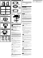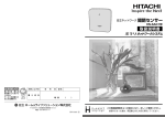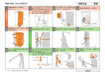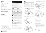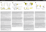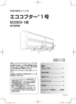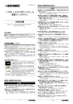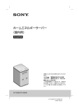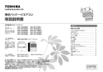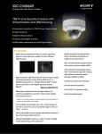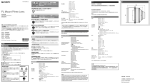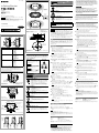
1
4-446-275-02(1) F 下記の注意を守らないと、けがをしたり 周辺の物品に損害を与えることがありま す。 In-Ceiling Bracket 取り付け時にネジを確実に締める ネジの締めつけが不充分な場合、本機が落下し、けがをする 原因となることがあります。 マークを合わせる / Aligning marks 取付説明書 Installation Instructions 指の挟み込みに注意する 金具を取り付ける際、金具と金具の間、または金具と天井の 間に指を挟み込まないように注意してください。 Instructions d’installation マーク / シャープエッジには素手で触れない 電気製品は、安全のための注意事項を守らないと、火災や人身事故に この製品には、鋭利なエッジが露出しており、手を触れると けがをするおそれがあります。 開梱および設置の際には、けがを防ぐため保護手袋を着用し てください。 なることがあります。 この取付説明書には、事故を防ぐための重要な注意事項と製品の取り扱いかたを示し ています。この取付説明書をよくお読みのうえ、製品を安全にお使いください。お読 みになったあとは、いつでも見られるところに必ず保管してください。 取り付けネジは付属のネジをご使用ください。付属品以外のネジを使用した場 合、本体内部を破損する恐れがあります。 日本語 G 天井の厚さ: 8 ~ 60 / 直径φ185.5 ~ 188.5の穴 / φ 185.5 to 188.5 (7 5/16 to 7 7/16) hole Thickness of the ceiling: 8 to 60 (10/32 to 2 3/8) 10 (13/32) 99 (4) A ˎˎ 天井などの高所に設置する場合は、専門の工事業者に依頼してください。 ˎˎ 高所への設置は、設置部および使用する取り付け部材(付属品を除く)が本機と カメラを含む重量に充分耐えられる強度があることをお確かめの上、確実に取 り付けてください。充分な強度がないと落下して大けがの原因となります。 ˎˎ カメラの落下事故防止のため、ワイヤーロープは必ず取り付けてください。 ◆◆詳しくは、カメラの設置説明書や取扱説明書をご覧ください。 53 (2 1/8) ˎˎ 高所へ設置した場合は、1年に一度は取り付けがゆるんでいないことを点検し てください。また、使用状況に応じて点検の間隔を短くしてください。 概要 YT-ICB600は、ネットワークカメラまたはカラービデオカメラ用の天井埋め込み Ø 208 (8 3 /16) 金具です。カメラ本体を天井に埋め込んで使用する場合や、石膏ボードなど天井 の材質がもろくネジで固定しにくい場合に使用します。 この取付説明書のカメラのイラストは、SNC-DH140またはSSC-FM531シリー ズを使用しています。 取り付けかた 位置/Position モデル/Model SNC-DH120/T -DH140/T -DH220/T -DH240/T -EM520 -EM521 -ZM550 -ZM551 11 天井にφ187 ± 1.5 mmの穴を開ける。 例: SNC-DH140 / 単位: ミリ / Unit: mm (inches) Example: SNC-DH140 ソニー製品は安全に充分配慮して設計されています。しかし、電気製品は、まち がった使いかたをすると、火災や感電などにより死亡や大けがなど人身事故につ ながることがあり、危険です。事故を防ぐために次のことを必ずお守りください。 ˎˎ 安全のための注意事項を守る。 SSC-FM530 -FM531 -FM560 -FM561 -N20/A -N21 -N22/A -N24/A 警告表示の意味 注意を促す記号 この取付説明書および製品では、次のような表 示をしています。表示の内容をよく理解してか ら本文をお読みください。 上記以外のモデルはカメラの設置説明書や取扱説明書をご覧ください。 For the model not listed above, refer to the Installation Manual or the Operating Instructions of the camera. B この表示の注意事項を守らないと、火災や 感電などにより死亡や大けがなど人身 事故につながることがあります。 行為を指示する記号 この表示の注意事項を守らないと、感電やその 他の事故によりけがをしたり周辺の物品に 損害を与えたりすることがあります。 下記の注意を守らないと、火災や感電に より死亡や大けがにつながることがあ ります。 設置は専門の工事業者に依頼する マークを合わせる / 例: SNC-DH140 / Example: SNC-DH140 M4ネジ / M4 screws ブラケット(カメラに付属)/ Bracket (supplied with the camera) C 設置については、必ずお買い上げ店またはソニーの相談窓口 にご依頼ください。 壁面や天井など高所への設置は、本機とカメラを含む重量に 充分耐えられる強度があることをお確かめください。充分 な強度がないと、落下して、大けがの原因となります。 また、1年に一度は、取り付けがゆるんでないことを点検し てください。また、使用状況に応じて、点検の間隔を短くし てください。 不安定な場所に設置しない 次のような場所に設置すると、倒れたり落ちたりして、故障 やけがの原因となることがあります。 ˎˎ 不安定な場所 ˎˎ 振動や衝撃のかかるところ また、設置・取り付け場所の強度を充分にお確かめください。 指定されたカメラに取り付ける 指定以外のカメラを取り付けると、しっかりと固定されない ため部品やカメラが落下し、足などにけがをする原因となる ことがあります。 接続コード類を傷つけない 例: SSC-FM531 / Example: SSC-FM531 接続コードを傷つけると、火災や感電の原因となることがあ ります。 ˎˎ 本機と天井などの間にコードを挟み込まない。 ˎˎ コード類を接続したまま移動しない。 M4ネジ / M4 screws D 分解や改造をしない 直径φ185.5 ~ 188.5の穴 / ø 185.5 to 188.5 (7 5/16 to 7 7/16) hole マウンティング プレート / Mounting plate 天井 / 8 ~ 60 / 8 to 60 (10/32 to 2 3/8) Ceiling 固定板 / 固定板 / Fixing plate Fixing plate 単位: ミリ / Unit: mm (inches) E 固定板 / Fixing plate 取り付け / Installing 取りはずし / Removing 天井の穴は指定された大きさで開けてください。天井の穴が指定された大き さではない場合、落下して大けがの原因となります。 22 カメラ本体からドームケースをはずす。 ◆◆詳しくは、カメラの設置説明書や取扱説明書をご覧ください。 33 カメラの型に応じて、ブラケット固定位置をセットする: 左右の金具の ネジ(各1本)をはずし、取り外したネジを、表に示す正しいネジ穴に固定 する。 (図) 44 本機付属のM4ネジを使用して、天井埋め込み金具にカメラを取り付ける。 行為を禁止する記号 * 旧金具(YT-ICB140)の「+スペーサ」に該当します。 * Corresponds to with spacer, for previous model (YT-ICB140) 付属のテンプレートをご利用ください。 テンプレートの4か所の長穴は、カメラの中心位置を決めるときにご利 用ください。 天井の材質により固定板が固定されにくい場合は、マウンティング プ レートを固定板の当たる場所に貼り付けて補強してください。 (図) ご注意 安全のために SSC-CM564R -CM565R SNC-VM600/B -VM630/VM631 -VM601/B -EM600/EM601 -EM630/EM631 Aligning marks ˎˎCheck that the thickness of the ceiling is from 8 mm (10/32 inches) to 60 mm (2 3/8 inches) inclusive. ˎˎMake a ø187 ± 1.5 mm (7 3/8 ± 1/16 inches) hole in the ceiling. ˎˎDo not scratch your hands on the sharp edges; this may cause injury. ˎˎBefore attempting installation, wear gloves to prevent injury. ˎˎIf the screws are not properly tightened, the camera may fall and cause serious injury. The YT-ICB600 is an in-ceiling bracket designed for use with Network Cameras and Color Video Cameras. It is used when the body of the camera is embedded in the ceiling, or with gypsum or plaster boards, where the quality of the material used in the ceiling makes it difficult for ordinary screws to hold. The illustrations used in this manual show the SNC-DH140 and SSC-FM531 series cameras. 1 Make a ø 187 ± 1.5 mm (7 / ± / 16 inches) hole in the ceiling. Use the supplied template. The four slotted holes on the template are usable when you decide the center position of the camera. If the quality of the material used in the ceiling makes it difficult to support the fixing plate, attach the supplied mounting plate where the fixing plate comes in contact with the ceiling for reinforcement. (Fig. ) 3 © 2012 Sony Corporation Printed in China * CAUTION Installing the In-Ceiling Bracket YT-ICB600 For details, refer to the Installation Manual or the Operating Instructions of the camera. ˎˎIf you install the camera at a height, check periodically, at least once a year, to ensure that the connection has not loosened. If conditions warrant, perform this periodic check more frequently. Overview Notch お買い上げいただきありがとうございます。 not strong enough, the camera may fall and cause serious injury. ˎˎTo prevent the camera from falling, be sure to attach a wire rope. 分解や改造をすると、金具の強度が低下し、設置している製 品が落下してけがの原因となることがあります。 機器や部品の取り付けは正しく行う 別売りの機器や部品の取り付け方法を誤ると、機器が落下し てけがをすることがあります。機器や部品を取り付けると きは、取付説明書をよく読んだうえ、確実に取り付けてくだ さい。 (図) ˎˎカメラ付属のブラケットを使用する。 ブラケットに△マークがあるときはマークと金具の切りかきを合わ せて取り付けてください。 (SNC-DH120/T、DH140/T、DH220/T、 DH240/T、EM520、EM521、VM600、VM600B、VM601、 VB601B、VM630、VM631、EM600、EM601、EM630、EM631、 ZM550、ZM551、SSC-CM564R、CM565R) (図) ˎˎカメラ本体を直接取り付ける。 ◆◆詳しくは、カメラの設置説明書や取扱説明書をご覧ください。 ご注意 本機の穴の中心と、カメラの底面またはカメラに付属のブラケットの中心を 合わせて取り付けてください。中心がずれていると、カバーが取り付けられ ない場合があります。 55 カメラにケーブルを接続する。 66 金具の左右にある固定板が閉じていること(図)(工場出荷状態)を 確認してから、カメラと金具が一体になったものを天井の穴に組み込 む。 (図) 77 金具の左右のネジを締め、金具で天井を挟む。 ネジを締めると、閉じていた固定板が外側へ回転して開きます。 (図) さらにネジを締めると固定板が下がって天井を挟みます。 (図) 固定板が天井をしっかり挟んでいることを確認してください。 ご注意 ネジを締めるときは、0.45 N・m ∼ 0.75 N・m(4.5 kgf・cm ∼ 7.5 kgf・cm)のトルクで締めてください。あまり強く締めると埋め込み金 具が壊れることがあります。 88 カメラの撮影方向や画角を調整する。 ◆◆詳しくは、カメラの設置説明書や取扱説明書をご覧ください。 99 ドームケースをカメラ本体に取り付ける。 ◆◆詳しくは、カメラの設置説明書や取扱説明書をご覧ください。 111本機のカバーを取り付ける。(図) 付属のカバーを金具にかぶせ、突き当たるまで時計回りに回す。 カバーをかぶせるときは、カバー横の線を金具の位置合わせ線に合 わせます。 カバーをネジで固定する。 ご注意 ネジを締めるときは、0.6 N・m(6 kgf・cm)∼ 0.7 N・m(7 kgf・cm) のトルクで締めてください。 天井埋め込み金具のはずしかた 11 カバーを天井に押さえつけながらネジをはずす。 22 カバーを突き当たるまで反時計回りに回し、下方に引き抜く。 33 固定板が閉じるまで左右のネジをゆるめてから(図)、金具とカメラを はずす。 ご注意 ˎˎ カバーは垂直方向にはずしてください。 ˎˎ 固定板が閉じた状態からさらに取りはずし方向へネジを回さないでください。 固定板が上部に強く突き当たると破損のおそれがあります。 ˎˎ ネジをゆるめるときはカメラを押さえてください。金具やカメラが落ちる危 険があります。 仕様 質量 外形寸法 付属品 約460 g(カバー含む) 図をご覧ください。 テンプレート(1)、M4ネジ(2)、 マウンティング プレート(2)、取付説明書(一式) 本機の仕様および外観は、改良のため予告なく変更することがありますが、ご了 承ください。 English WARNING ˎˎThis installation should be made by a qualified service person and should conform to all local codes. ˎˎEnsure that the installation location and its material are strong enough to withstand the gross weight of the camera and the In-Ceiling Bracket, and then install the camera securely. If they are 8 1 Note Follow the specified size when making the hole in the ceiling. If the hole is too large, the camera may fall, resulting in injury. 2 Remove the dome casing from the camera. For details, refer to the Installation Manual or the Operating Instructions of the camera. 3 Set the bracket fixing position according to the camera model: Remove the screws from the left and right side brackets (one screw each) and fix the removed screws in the proper screw holes by referring to the table. (Fig. ) 4 Using the supplied M4 screws, attach the camera to the In-Ceiling Bracket. ˎˎUse the bracket supplied with the camera. (Fig. ) If the bracket has marks, align the marks to the notches on the In-Ceiling Bracket before installation. (SNC-DH120/T, DH140/T, DH220/T, DH240/T, EM520, EM521, VM600, VM600B, VM601, VB601B, VM630, VM631, EM600, EM601, EM630, EM631, ZM550, ZM551, SSC-CM564R, CM565R) ˎˎDirectly attach the camera. (Fig. ) For details, refer to the Installation Manual or the Operating Instructions of the camera. Note When attaching, align the center of the hole on the In-Ceiling Bracket with the center of the bottom of the camera or the center of the bracket supplied with the camera. The cover of the In-Ceiling Bracket may not be attached if the centers are misaligned. 5 Connect the cables to the camera. 6 Be sure that the right and left fixing plates of the In-Ceiling Bracket are closed (Fig. ) (default position), and install the In-Ceiling Bracket with the camera on the ceiling. (Fig. ) 7 Tighten the left and right screws of the In-Ceiling Bracket to secure it to the ceiling. As you tighten the screws, the fixing plates swing outward (Fig. ) and lower to grip the ceiling. (Fig. ) Be sure that the fixing plates grip the ceiling firmly. Note Torque the screws to 0.45 N•m to 0.75 N•m (4.5 kgf•cm to 7.5 kgf•cm) to tighten them. Tightening the screws too hard may cause damage to the In-Ceiling Bracket. 8 Adjust the shooting direction and range of the camera. For details, refer to the Installation Manual or the Operating Instructions of the camera. 9 Attach the dome casing to the camera’s unit casing. For details, refer to the Installation Manual or the Operating Instructions of the camera. 10Install the supplied cover. (Fig. ) Align the notch on the cover with the mark on the bracket, press the cover against the bracket, and then turn the cover clockwise until it stops. Secure the cover with screws. Note Torque the screws to 0.6 N·m (6 kgf·cm) to 0.7 N·m (7 kgf·cm). Removing the In-Ceiling Bracket 1 Hold the cover, and then remove the screws on the cover. 2 Turn the cover counter-clockwise until it stops, and then pull the cover down. 3 Loosen the left and right screws of the In-Ceiling Bracket (Fig. ) to fold the fixing plates, and then remove the In-Ceiling Bracket with the camera. Notes ˎˎRemove the cover vertically. ˎˎDo not attempt to further loosen the left and right screws of the In-Ceiling Bracket when the fixing plates are in a closed position. Damage may incur if the fixing plates forcefully press against the upper part of the In-Ceiling Bracket. ˎˎHold the camera while loosening the screws; otherwise the In-Ceiling Bracket and the camera may fall. Specifications Mass Dimensions Supplied accessories Approx. 460 g (1 lb 9/40 oz) (including the cover) See Fig. . Template (1), M4 screws (2), Mounting plate (2), Installation Instructions (1 set) The exterior appearance and specifications are subject to changes without prior notice. 3 A F 球嵌入安装支架连同摄像机一起拆下。 注意 • 请垂直拆下盖子。 • 固定板处于闭合位置时,切勿试图进一步拧松半球嵌入安装支架的左右 螺丝。 如果固定板强行压住半球嵌入安装支架的上部,则可能会造成损坏。 • 拧松螺丝时请托住摄像机,否则半球嵌入安装支架和摄像机可能会掉落。 规格 质量 尺寸 附件 约460 g(包括盖子) 参见图 。 模板(1),M4螺丝(2),安装板(2), 安装说明书(1套) 外形和规格如有变更,恕不另行通知。 出版日期: 2013年6月 / Repères d’alignement /Position /Modèle Français / Encoche SNC-DH120/T -DH140/T -DH220/T -DH240/T -EM520 -EM521 -ZM550 -ZM551 AVERTISSEMENT ˎˎL’installation doit être effectuée par un technicien qualifié et se conformer aux réglementions locales. ˎˎAssurez-vous que l’emplacement et le support d’installation sont suffisamment solides pour supporter le poids de la caméra et celui du support de fixation au plafond, puis installez correctement la caméra. En cas de résistance insuffisante, la caméra risque de tomber et de provoquer des blessures graves. ˎˎVeillez à fixer un câble métallique pour éviter toute chute de la caméra. SSC-CM564R -CM565R SNC-VM600/B -VM630/VM631 -VM601/B -EM600/EM601 -EM630/EM631 Pour plus de détails, reportez-vous au Manuel d’installation ou au Mode d’emploi de la caméra. SSC-FM530 -FM531 -FM560 -FM561 -N20/A -N21 -N22/A -N24/A * ˎˎSi vous installez la caméra en hauteur, effectuez une vérification régulièrement, au moins une fois par an, afin de vous assurer que l’ensemble n’est pas desserré. Si les conditions le permettent, effectuez cette vérification plus fréquemment. G / / Épaisseur du plafond : 8 à Trou de 185,5 à 188,5 (7 5/16 à 7 7/16) de diamètre 60 (10/32 à 2 3/8) * B 53 (2 1/8) 10 (13/32) Si le modèle n’est pas indiqué dans la liste ci-dessus, reportez-vous au Manuel d’installation ou au Mode d’emploi de la caméra. 99 (4) * Correspond au modèle avec entretoise pour le modèle précédent (YT-ICB140) ATTENTION ˎˎVérifiez que l’épaisseur du plafond est comprise entre 8 mm (10/32 pouces) et 60 mm (2 3/8 pouces). ˎˎPercez un trou de 187 ± 1,5 mm (7 3/8 ± 1/16 pouces) de diamètre dans le plafond. ˎˎNe passez pas les mains sur les bords coupants car vous pourriez vous blesser. ˎˎAvant de procéder à l’installation, enfilez des gants pour ne pas vous blesser. ˎˎSi les vis ne sont pas bien serrées, la caméra risque de tomber et de provoquer de graves blessures. Description générale Ø 208 (8 / Repères d’alignement / Vis M4 / Exemple : SNC-DH140 3 /16) Installation du support de fixation au plafond / Support (fourni avec la caméra) / Exemple : SNC-DH140 C / Unité : mm (pouces) 中文 使用产品前请仔细阅读本书,并请妥善保管。 警告 / Exemple : SSC-FM531 • 本安装必须由授权的专业人员进行并符合当地法规。 • 必须确保安装位置及其材质有足够的强度承受摄像机和半球嵌入安装支 架的总重量,然后再牢固安装摄像机。如果强度不够,则摄像机可能掉 落并造成严重的人员受伤。 • 为防止摄像机掉落,必须连接钢绳。 详细说明,请参阅摄像机的安装手册或使用说明书。 • 如果摄像机安装在高处,请定期检查,每年至少一次,以确保连接没有 松动。如果条件允许,请更频繁定期检查。 / Vis M4 D 注意 / Trou de 185,5 à 188,5 (7 5/16 à 7 7/16) de diamètre / Plaque de montage / 8 à 60 (10/32 à 2 3/8) / Plafond / Plaque de fixation / Plaque de fixation • • • • • 检查天花板的厚度是否在8 mm至60 mm之间。 在天花板上打一个ø 187 ± 1.5 mm的孔。 切勿让您的手被锋利的边缘刮到;否则可能会造成受伤。 尝试安装之前,请戴上手套防止受伤。 如果未正确拧紧螺丝,则摄像机可能掉落并造成严重的人员受伤。 关于废弃产品的处理 请不要将废弃的产品与一般生活垃圾一同弃置。 正确处置废弃的产品有助于避免对环境和人类健康造成潜在的负面影 响。 具体的处理方法请遵循当地的规章制度。 概述 / Unité : mm (pouces) E YT-ICB600是专为配合网络摄像机和彩色摄像机使用而设计的半球嵌入安装 支架。当需要摄像机机身嵌入天花板或含有石膏或灰泥的板材时,天花板中 所使用的材质会难以固定普通螺丝,此时请使用此支架。 本手册中所使用的插图为SNC-DH140和SSC-FM531系列摄像机。 安装半球嵌入安装支架 1 在天花板上打一个ø 187 ± 1.5 mm的孔。 使用附带的模板。在确定摄像机的中心位置时,可以使用模板上四个 插槽孔。 如果天花板所使用的材质难以支撑固定板,请将附带的安装板安装于 固定板与天花板的连接处以进行加固。 (图 ) / Plaquede fixation 注意 / Pose / Retrait Le support YT-ICB600 est un support de fixation au plafond conçu pour être utilisé avec les caméras réseau et les caméras vidéo couleur. Ce support est nécessaire lorsque le corps de la caméra est incrusté dans le plafond ou lorsque des plaques de plâtre sont utilisées et que la qualité du matériau entrant dans la composition du plafond rend difficile la tenue de vis ordinaires. Les illustrations de ce manuel représentent les modèles de caméra SNC-DH140 et SSC-FM531. 按照指定的尺寸在天花板中钻孔。如果孔过大,摄像机可能会掉落,造 成人员受伤。 从摄像机上拆下圆顶盖。 详细说明,请参阅摄像机的安装手册或使用说明书。 2 3 4 根据摄像机型号设定支架安装位置:拆下左右两侧支架的螺丝(每侧 一个螺丝),并将拆下的螺丝拧入表中所示的正确螺丝孔。 (图 ) 使用附带的M4螺丝,将摄像机安装于半球嵌入安装支架。 (图 ) 使用摄像机附带的支架。 如果支架有标记,安装之前将标记对准半球嵌入安装支架上的 缺口。 (SNC-DH120/T、DH140/T、DH220/T、DH240/T、EM520、 EM521、VM600、VM600B、VM601、VB601B、VM630、VM631、EM600、 EM601、EM630、EM631、ZM550、ZM551、SSC-CM564R、CM565R) (图 ) 直接安装摄像机。 详细说明,请参阅摄像机的安装手册或使用说明书。 注意 安装时,将半球嵌入安装支架上孔的中心对准摄像机底部的中心或摄 像机附带的支架的中心。如果中心未对准,则可能无法安装半球嵌入 安装支架的盖子。 将电缆连接至摄像机。 5 6 确保半球嵌入安装支架的左右固定板处于闭合位置(图 ) (默认 位置),然后再将连着摄像机的半球嵌入安装支架安装在天花板上。 (图 ) 7 拧紧半球嵌入安装支架的左右螺丝,将其固定在天花板上。 在拧紧螺丝时,固定板将向外转动(图 ),并下降以夹紧天花板。 (图 ) 必须确保固定板夹紧天花板。 注意 8 9 10 使用0.45 N•m至0.75 N•m的扭矩拧紧螺丝。螺丝拧得过紧可能会损坏半 球嵌入安装支架。 调整摄像机的拍摄方向和覆盖范围。 详细说明,请参阅摄像机的安装手册或使用说明书。 将圆顶外壳安装在摄像机外壳上。 详细说明,请参阅摄像机的安装手册或使用说明书。 安装附带的盖子。 (图 ) 将盖子上的缺口对准支架上的标记,将盖子按入支架,然后顺时针拧紧 盖子。 用螺丝固定盖子。 注意 螺丝扭矩为0.6 N·m至0.7 N·m。 拆卸半球嵌入安装支架 1 2 3 托住盖子,然后拆下盖子上的螺丝。 将盖子逆时针转到底,然后将盖子拆下。 拧松半球嵌入安装支架的左右螺丝(图 )使固定板折叠,然后将半 球嵌入安装支架连同摄像机一起拆下。 注意 • 请垂直拆下盖子。 • 固定板处于闭合位置时,切勿试图进一步拧松半球嵌入安装支架的左右 1 Percez un trou de 187 ± 1,5 mm (7 / ± / 3 1 8 16 pouces) de diamètre dans le plafond. Utilisez le gabarit fourni. Vous pouvez utiliser les quatre trous du gabarit si vous choisissez la position centrale de la caméra. Si la qualité du matériau utilisé pour le plafond ne permet pas de soutenir aisément la plaque de fixation, attachez la plaque de montage fournie à l’endroit où la plaque de fixation entre en contact avec le plafond afin de la renforcer. (Fig. ) Remarque Respectez la taille spécifiée lors du perçage du trou au plafond. Si le trou est trop grand, la caméra risque de tomber, ce qui pourrait entraîner des blessures. 2 Retirez le dôme de la caméra. Pour plus de détails, reportez-vous au Manuel d’installation ou au Mode d’emploi de la caméra. la position de fixation du support selon le modèle de la caméra : 3 Réglez retirez les vis des supports latéraux gauche et droit (une vis chacun), puis insérez ces vis dans les orifices appropriés en vous reportant au tableau. (Fig. ) 4 À l’aide des vis M4 fournies, attachez la caméra au support de fixation au plafond. ˎˎUtilisez le support fourni avec la caméra. (Fig. ) Si le support possède des repères , alignez les repères sur les encoches du support de fixation au plafond avant l’installation. (SNC-DH120/T, DH140/T, DH220/T, DH240/T, EM520, EM521, VM600, VM600B, VM601, VB601B, VM630, VM631, EM600, EM601, EM630, EM631, ZM550, ZM551, SSC-CM564R, CM565R) ˎˎFixez directement la caméra. (Fig. ) Pour plus de détails, reportez-vous au Manuel d’installation ou au Mode d’emploi de la caméra. Remarque Lors de la fixation, alignez le centre de l’orifice du support de fixation au plafond avec le centre de la partie inférieure de la caméra ou le centre du support fourni avec la caméra. Il est possible que le couvercle du support de fixation au plafond ne puisse pas être fixé si les centres sont mal alignés. 5 Reliez les câbles à la caméra. 6 Veillez à ce que les plaques de fixation droite et gauche du support de fixation au plafond soient fermées (Fig. ) (position par défaut), puis installez le support de fixation au plafond avec la caméra au plafond. (Fig. ) 7 Resserrez les vis droite et gauche du support de fixation au plafond pour le fixer fermement au plafond. Lorsque vous serrez les vis, les plaques de montage basculent vers l’extérieur (Fig. ) et s’abaissent pour adhérer au plafond. (Fig. ) Assurez-vous que les plaques de fixation adhèrent solidement au plafond. Remarque Le couple de serrage des vis doit être compris entre 0,45 N·m et 0,75 N·m (4,5 kgf·cm à 7,5 kgf·cm). Un couple de serrage trop élevé risque d’endommager le support de fixation au plafond. 8 Réglez l’orientation de la prise de vue et la portée de la caméra. Pour plus de détails, reportez-vous au Manuel d’installation ou au Mode d’emploi de la caméra. 9 Fixez correctement le dôme à la caméra. Pour plus de détails, reportez-vous au Manuel d’installation ou au Mode d’emploi de la caméra. 10Installez le couvercle fourni. (Fig. ) Alignez l’encoche du couvercle avec le repère du support, poussez le couvercle contre le support et tournez le couvercle dans le sens des aiguilles d’une montre jusqu’à ce qu’il s’arrête. Fixez le couvercle à l’aide des vis. Remarque Serrez les vis à un couple compris entre 0,6 N·m (6 kgf·cm) et 0,7 N·m (7 kgf·cm). Dépose du support de fixation au plafond 1 Maintenez le couvercle, puis retirez les vis. 2 Tournez à fond le couvercle dans le sens inverse des aiguilles d’une montre, puis abaissez-le. 3 Desserrez les vis gauche et droite du support de fixation au plafond (Fig. ) afin de plier les plaques de montage, puis retirez le support de fixation au plafond avec la caméra. Remarques ˎˎRetirez le couvercle verticalement. ˎˎN’essayez pas de desserrer davantage les vis gauche et droite du support de fixation au plafond lorsque les plaques de fixation sont en position fermée. Une pression trop importante des plaques de fixation sur la partie supérieure du support de fixation au plafond risque de provoquer des dégâts. ˎˎMaintenez bien la caméra lorsque vous desserrez les vis, sinon le support de fixation au plafond et la caméra risquent de tomber. Spécifications Poids Dimensions Accessoires fournis Environ 460 g (1 lb 9/40 oz) (couvercle inclus) Voir Fig. . Gabarit (1), Vis M4 (2), Plaque de montage (2), Instructions d’installation (1 exemplaire) L’aspect extérieur et les spécifications peuvent faire l’objet de modifications sans préavis.