1
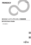
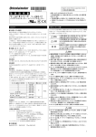
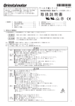
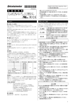
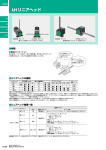
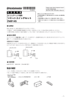
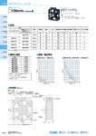
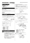
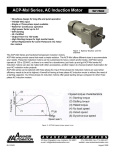
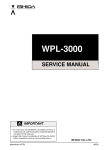
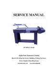
HM-9189-2 取 扱 説 明 書 ワールド K シリーズ 端子箱付タイプ インダクションモーター、レバーシブルモーター お買い上げいただきありがとうございます。 この取扱説明書には、製品の取り扱いかたや安全上の注意事項を示し ています。 ・取扱説明書をよくお読みになり、製品を安全にお使いください。 ・お読みになったあとは、いつでも見られるところに必ず保管してくださ い。 English version follows Japanese version. お使いになる前に 安全上のご注意 はじめに 製品の取り扱いは、適切な資格を有する人が行なってください。 お使いになる前に、「安全上のご注意」をよくお読みのうえ、正しくお使い ください。 製品内部の点検や修理が必要なときは、お買い上げになった支店・営業 所にご連絡ください。 この製品は、一般的な産業機器の機器組み込み用として設計されていま す。その他の用途には使用しないでください。この警告を無視した結果 生じた損害の補償については、当社は一切その責任を負いませんので、 あらかじめご了承ください。 ここに示した注意事項は、製品を安全に正しくお使いいただき、お客様 や他の人々への危害や損傷を未然に防止するためのものです。内容を よく理解してからお使いください。 重 要 規格・CE マーキング モーターは下記の規格にしたがって設計・検査を行なっており、認定を 取得しています。認定品名は、モーター品名です。 モーター(5IK90GU-SWT、5IK90A-SWT、5IK150A-TWT を除く)は VDE 認定を取得しています。VDE 認定は、モーター単体での認定となります。 単相モーターは、付属コンデンサとモーターの組合せで EN 60950-1 Annex B.8 項の試験に合格しています。 5IK90GU-SWT、5IK90A-SWT は DEMKO の認定を取得しています。 ※モーターは低電圧指令に適合しています。 • 爆発性雰囲気、引火性ガスの雰囲気、腐食性の雰囲気、水のかかる • • ● 認定規格 UL 1004、UL 2111、CSA C22.2 No.100、CSA C22.2 No.77、EN 60950-1 • ● 認定機関 UL File No. E64199(6 W タイプ)、E64197(25~150 W タイプ)、 VDE、DEMKO • EN 60034-1、EN 60034-5、IEC 60034-11、IEC 60664-1、EN 60950-1 • • 上記規格で要求される過負荷運転試験および拘束温度上昇試験は、歯 切りシャフトタイプはギヤヘッド付き、丸シャフトタイプは放熱板付きの状 態で行なっています。放熱板のサイズ、材質は以下のとおりです。 • ● 適合規格 モーター品名の 1 文字目 2 4 5(40 W) 5(60 W、90 W、150 W) サイズ(mm) 115 × 115 135 × 135 165 × 165 200 × 200 厚さ(mm) 材 質 • 5 アルミ • ● 設置条件 過電圧カテゴリーⅡ、汚染度 2、クラスⅠ機器(適用規格 EN/IEC 規格) 機器によって過電圧カテゴリーⅢ、汚染度 3 の規定値が要求される場合 は、モーターを IP54 相当のキャビネットに収納し、絶縁トランスを介して モーターには定格電圧を給電してください。 ● 付属品の規格認定 この警告事項に反した取り扱いをすると、死亡また は重傷を負う場合がある内容を示しています。 この注意事項に反した取り扱いをすると、傷害を負う または物的損害が発生する場合がある内容を示し ています。 製品を正しくお使いいただくために、お客様に必ず 守っていただきたい事項を本文中の関連する取り扱 い項目に記載しています。 • • • • 場所、可燃物のそばでは使用しないでください。火災・感電・けがの原 因になります。 設置、接続、運転・操作、点検・故障診断の作業は、適切な資格を有 する人が行なってください。火災・感電・けがの原因になります。 通電状態で移動、設置、接続、点検の作業をしないでください。電源を 切ってから作業してください。感電の原因になります。 モーターの過熱保護装置(サーマルプロテクタ)がはたらいたときは、 電源を切ってください。過熱保護装置が自動復帰したときにモーター が突然起動して、けが・装置破損の原因になります。 モーターは、クラスⅠ機器のみに使用してください。感電の原因になり ます。 モーターは筐体内に設置してください。感電・けがの原因になります。 設置するときは、モーターに手が触れないようにするか、接地してくだ さい。感電の原因になります。 保護接地端子があるものは、保護接地端子を使って、必ず接地してく ださい。 電源入力電圧は、定格値を必ず守ってください。火災・感電の原因に なります。 接続は接続図にもとづき、確実に行なってください。火災・感電の原因 になります。 リード線を無理に曲げたり、引っ張ったり、はさみ込んだりしないでくだ さい。火災・感電の原因になります。 付属のコンデンサの接続端子は絶縁処理してください。感電の原因に なります。 停電したときは、電源を切ってください。停電復旧時にモーターが突然 起動して、けが・装置破損の原因になります。 電源を切った直後(30 秒以内)は、コンデンサの接続端子に触れない でください。残留電圧により、感電の原因になります。 モーターを分解・改造しないでください。感電・けがの原因になります。 コンデンサ: UL File No. E83671(CYWT2)、VDE License No.114747 (コンデンサ定格電圧 450 VAC タイプのみ) コンデンサキャップ: UL File No.E56078(YDTU2) 電気用品安全法 三相モーター丸シャフトタイプは、 マークを表示しています。 1 ● レバーシブルモーター • モーターの仕様値を超えて使用しないでください。感電・けが・装置破 損の原因になります。 • 運転中および停止後しばらくの間は、モーターに触れないでください。 モーターの表面が高温のため、やけどの原因になります。 • モーター出力軸を持たないでください。けがの原因になります。 • モーターの周囲には、可燃物を置かないでください。火災・やけどの原 因になります。 • モーターの周囲には、通風を妨げる障害物を置かないでください。装 置破損の原因になります。 • 運転中は回転部(出力軸、冷却ファン)に触れないでください。けがの 原因になります。 • 異常が発生したときは、ただちに電源を切ってください。火災・感電・け がの原因になります。 • モーターは、正常な運転状態でも、表面温度が 70 ℃を超えることがあります。運転中のモーターに 接近できるときは、図の警告ラベルをはっきり見える 警告ラベル 位置に貼ってください。やけどの原因になります。 • モーターを廃棄するときは、できるだけ分解し、産業廃棄物として処理 してください。 準 備 製品の確認 パッケージを開封し、次のものがすべて揃っていることを確認してください。 不足している場合や破損している場合は、お買い求めの支店・営業所ま でご連絡ください。 • モーター.............................. 1 台 • コンデンサ........................... 1 個(単相モーターのみ) • コンデンサキャップ ............. 1 個(単相モーターのみ) • 取扱説明書(本書) ............ 1 部 品名の確認 製品が正しいか、製品に表示された品名で確認してください。 ● インダクションモーター 品 名 2IK6GN-AWTJ ∗ 2IK6GN-AWTU ∗ 2IK6GN-CWTJ ∗ 2IK6GN-CWTE ∗ 4IK25GN-AWTJ 4IK25GN-AWTU 4IK25GN-CWTJ 4IK25GN-CWTE 5IK40GN-AWTJ 5IK40GN-AWTU 5IK40GN-CWTJ 5IK40GN-CWTE 5IK60GU-AWTJ 5IK60GU-AWTU 5IK60GU-CWTJ 5IK60GU-CWTE 5IK90GU-AWTJ 5IK90GU-AWTU 5IK90GU-CWTJ 5IK90GU-CWTE 2IK6GN-SWT ∗ モーター品名 2IK6GN-AWT ∗ 2IK6GN-AWT ∗ 2IK6GN-CWT ∗ 2IK6GN-CWT ∗ 4IK25GN-SWT 5IK40GN-SWT 5IK60GU-SWT 5IK90GU-SWT 5IK150A-TWT 4IK25GN-SWT 5IK40GN-SWT 5IK60GU-SWT 5IK90GU-SWT 5IK150A-TWT 4IK25GN-AWT 4IK25GN-AWT 4IK25GN-CWT 4IK25GN-CWT 5IK40GN-AWT 5IK40GN-AWT 5IK40GN-CWT 5IK40GN-CWT 5IK60GU-AWT 5IK60GU-AWT 5IK60GU-CWT 5IK60GU-CWT 5IK90GU-AWT 5IK90GU-AWT 5IK90GU-CWT 5IK90GU-CWT 2IK6GN-SWT ∗ コンデンサ品名 CH35FAUL CH25FAUL CH08BFAUL CH06BFAUL CH80CFAUL CH65CFAUL CH18BFAUL CH15BFAUL CH110CFAUL CH90CFAUL CH30BFAUL CH23BFAUL CH200CFAUL CH180CFAUL CH50BFAUL CH40BFAUL CH280CFAUL CH200CFAUL CH70BFAUL CH60BFAUL - - - - - - 品 名 モーター品名 コンデンサ品名 2RK6GN-AWTJ ∗ 2RK6GN-AWT ∗ CH45FAUL 2RK6GN-AWTU ∗ 2RK6GN-AWT ∗ CH35FAUL 2RK6GN-CWTJ ∗ 2RK6GN-CWT ∗ CH10BFAUL 2RK6GN-CWTE ∗ 2RK6GN-CWT ∗ CH08BFAUL 4RK25GN-AWTJ 4RK25GN-AWT CH100CFAUL 4RK25GN-AWTU 4RK25GN-AWT CH80CFAUL 4RK25GN-CWTJ 4RK25GN-CWT CH25BFAUL 4RK25GN-CWTE 4RK25GN-CWT CH20BFAUL 5RK40GN-AWTJ 5RK40GN-AWT CH160CFAUL 5RK40GN-AWTU 5RK40GN-AWT CH120CFAUL 5RK40GN-CWTJ 5RK40GN-CWT CH40BFAUL 5RK40GN-CWTE 5RK40GN-CWT CH35BFAUL 5RK60GU-AWTJ 5RK60GU-AWT CH250CFAUL 5RK60GU-AWTU 5RK60GU-AWT CH200CFAUL 5RK60GU-CWTJ 5RK60GU-CWT CH60BFAUL 5RK60GU-CWTE 5RK60GU-CWT CH50BFAUL 5RK90GU-AWTJ 5RK90GU-AWT CH350CFAUL 5RK90GU-AWTU 5RK90GU-AWT CH300CFAUL 5RK90GU-CWTJ 5RK90GU-CWT CH80BFAUL 5RK90GU-CWTE 5RK90GU-CWT CH70BFAUL 品名およびモーター品名は歯切りシャフトタイプです。 丸シャフトタイプの場合、品名およびモーター品名の「GN」「GU」は「A」 になります。ただし、5IK150A-TWT は丸シャフトタイプのみ、*印が付い ているモーターは歯切りシャフトタイプのみです。 設 置 設置場所 モーターは機器組み込み用に設計、製造されています。 風通しがよく、点検が容易な次のような場所に設置してください。 • 屋内に設置された筐体内(換気口を設けてください) • 使用周囲温度 -10~+40 ℃(凍結しないこと) 100/200 V 運転時は-10~+50 ℃ • 使用周囲湿度 85%以下(結露しないこと) • 爆発性雰囲気、有害なガス(硫化ガスなど)、および液体のないところ • 直射日光が当たらないところ • 塵埃や鉄粉などの少ないところ • 水(雨や水滴)、油(油滴)、およびその他の液体がかからないところ • 塩分の少ないところ • 連続的な振動や過度の衝撃が加わらないところ • 電磁ノイズ(溶接機、動力機器など)が少ないところ • 放射性物質や磁場がなく、真空でないところ • 標高 1000 m 以下 モーターの設置 ● 丸シャフトタイプ 取付板に穴をあけ、ねじ、ナット、ワッシャを使用し、モーターを取付板に 固定してください(取付用のねじは付属していません)。このとき、モー ター取付面と取付板にすきまがないようにしてください。 䊪䉾䉲䊞 䊝䊷䉺䊷 䊅䉾䊃 ขઃ↪䈰䈛 ขઃ᧼ モーター品名の 1 文字目 2 4 5 ねじの呼び M4 M5 M6 締付トルク 2.0 N·m 2.5 N·m 3.0 N·m 重 要 取付穴にモーターを斜めに挿入したり、無理に組み付けたりしないで ください。フランジインローに傷が付き、モーターが破損するおそれが あります。 2 ● 歯切りシャフトタイプ 接続および運転 取付板に穴をあけ、別売りのギヤヘッド付属のねじ 4 本を使用し、モー ターとギヤヘッドを取付面に固定してください。このとき、モーターフラン ジ面とギヤヘッドインロー端面にすきまがないようにしてください。 設置の詳細は、ギヤヘッドの取扱説明書を参照してください。 モーターリード線と電源接続部、コンデンサ接続部など、すべての接続 部は、絶縁処理をしてください。コンデンサ端子接続部の絶縁処理用に は、付属のコンデンサキャップを使用してください。 重 要 䊝䊷䉺䊷 モーターの絶縁階級は、B 種絶縁です。モーターを運転するときは モーターケース温度を 90 ℃以下に抑えてください。90 ℃を超えて 運転されると、モーターの巻線、ボールベアリングの寿命が短くな ります。モーターケースの温度は、温度計、サーモテープ、または 熱電対で測定・確認してください。 ᐔ䊪䉾䉲䊞 䉩䊟䊓䉾䊄ઃዻ䈱䈰䈛 䊅䉾䊃 䉩䊟䊓䉾䊄 単相インダクションモーターの回転方向は、モーターが完全に停止 してから切り替えてください。運転中に回転方向を切り替えると、回 転方向が切り替わらなかったり、切り替わるまでに時間がかかった りすることがあります。 ขઃ᧼ 重 要 モーターの歯切りタイプと同じ歯切りタイプのギヤヘッドを組み付けて ください。 単相モーターは付属のコンデンサを使用し、モーターが起動した後 もコンデンサは常時接続しておいてください。 ● 冷却ファン付モーター モーター後部の空気吸込口をふさがないように、ファンカバーの後ろを 10 mm 以上あけるか、換気穴をあけてください。 コンデンサの取り付け(単相モーターのみ) 付属コンデンサの容量が、モーター銘板に記 載されている容量と合っているか確認してくだ さい。 M4 のねじ(付属していません)を使用して、確 実に取り付けてください。 端子箱への接続 ● 6 W タイプ ┵ሶࠞࡃ ขઃߨߓ ┵ሶ䉦䊋䊷 䉯䊛䊑䉾䉲䊠 ┵ሶบ 䉬䊷䊑䊦 Ø4.3 mm ࠧࡓࠪ࠻ ┵ሶࠞࡃ ┵ሶบᐳ ࠧࡓࡉ࠶ࠪࡘ 重 要 • 適用ケーブル径:Ø6.8~8.6 mm • 端子カバーと端子台座との間に異物を挟み込まないように組み付けて ください。 • 端子箱のシール性を保つために、端子カバーと端子台座との間にゴム シートを使用しています。ゴムシートは端子台座に接着していますが、 脱落しないようにしてください。 • 端子カバー、端子台のねじの締付トルクは以下の表を参考に行なって ください。 端子カバー 端子台 0.3 N·m 0.8~1.0 N·m 重 要 適用ケーブル径をお守りください。 • ケーブルを端子台に接続するときは、できるだけ圧着端子をご使用く ださい。 適用圧着端子 絶縁被覆付き丸型端子 絶縁被覆付き先開端子 Ø3.6 mmએ 18 mmએਅ 3.6 mmએ 6.4 mmએਅ コンデンサは、モーターから 10 cm 以上離して取り付けてください。 モーターの熱で、コンデンサの寿命が短くなります。 ࠧࡓࠪ࠻ 7.2 mmએਅ コンデンサ取付用のねじの締付トルクは、取付足の破損防止のた め 1 N·m 以下にしてください。 18 mmએਅ • ケーブルの引出し口は、4 方向に変更し、固定することができます。端 子箱を組み付けるときに、方向を変更して固定してください。 3 接続図 ● 25~150 W タイプ ┵ሶ䉦䊋䊷ขઃ䈰䈛 㩿䉯䊛䉲䊷䊦㊄ዻ䊪䉾䉲䊞ઃ㪀 ┵ሶ䉦䊋䊷 図のように接続してください。 回転方向は、モーター出力軸側から見た場合です。時計方向を CW、反 時計方向を CCW としています。 䉲䊷䊦䉮䊈䉪䉺 䉺䊷䊚䊅䊦䊑䊨䉾䉪 䉬䊷䊑䊦䉪䊤䊮䊒 ┵ሶบᐳ 䉧䉴䉬䉾䊃 インダクションモーター 回転方向によって、接続方法が異なります。 時計方向 䉺䊷䊚䊅䊦䊑䊨䉾䉪 ┵ሶ䉦䊋䊷 6 W タイプ ● 単相モーター 䉬䊷䊑䊦䉪䊤䊮䊒 䉲䊷䊦䉮䊈䉪䉺 䉯䊛䊌䉾䉨䊮 U2 N U1 • 端子箱内の保護接地端子 U2 N 9 mmએਅ • ケーブルは、下記の適用範囲の仕様のものをお使いください。 0.5~0.7 N·m 2.5~3.8 N·m 0.2~0.3 N·m 0.5~0.8 N·m 重 要 端子箱のシール性を保つため、適用ケーブル径をお守りください。 モーター外部に露出したケーブルは、ストレスが加わらないように 固定してください。 䉮䊮䊂䊮䉰 レバーシブルモーター スイッチを CW 側に倒すと 時計方向、CCW 側に倒すと 反時計方向に回転します。 CW CCW L N CCW CW 端子箱の内部 Z2 U2 䊝䊷䉺䊷 U1 䉯䊛䊑䉾䉲䊠 䉮䊮䊂䊮䉰 ┵ሶขઃ䈰䈛 3-M3.5 ● 三相モーター U、V、W のうちのいずれか 2 線を入れ替えると、反時計方向に回転しま す。 CW L1䋨R䋩 U L2䋨S䋩 V L3䋨T䋩 W 端子箱の内部 U V W シールコネクタ:適用ケーブル径 Ø6~12 mm ターミナルブロック:適用リード線 AWG24~12(0.2~3.5 mm2) 皮むきの長さ 8 mm • 端子カバーと端子台座との間に異物を挟み込まないように組み付けて ください。 • 端子カバー取付ねじは専用ねじです。この専用ねじには、端子箱に防 塵・防沫性を持たせるため、ゴムシールと金属ワッシャがセットされてい ます。端子箱のシール性を保つために、端子カバー取付ねじ以外は 使用しないでください。 また、端子箱合わせ面のガスケットは、脱落しないような構造になってい ますが、万一外れた際には、端子箱溝部にしっかりと装着してください。 端子カバー、シールコネクタなどのねじの締付トルクは以下の表を参 考に行なってください。 䊝䊷䉺䊷 U1 Z2 U2 U1 を使って接地してください。三相モー ター丸シャフトタイプは、以下を参考にしてください。 Ø4.1 mmએ 適用圧着端子:絶縁被覆付き丸型圧着 端子 端子ねじサイズ:M4 締付トルク:1.0~1.3 N·m 4.5 mmએਅ 適用リード線:AWG18(0.75 mm2)以上 Z2 䊝䊷䉺䊷 䉮䊮䊂䊮䉰 䉧䉴䉬䉾䊃 4 L CCW L Z2 䉬䊷䊑䊦 ねじ締付トルク 端子カバー シールコネクタ ケーブルクランプ ターミナルブロック 反時計方向 CW 䊝䊷䉺䊷 䉯䊛䊑䉾䉲䊠 ┵ሶขઃ䈰䈛 3-M3.5 25~150 W タイプ 時間定格 ● 単相モーター ● インダクションモーター 連続運転が可能です(連続定格)。 インダクションモーター 回転方向によって、接続方法が異なります 時計方向 反時計方向 CW Z2 U2 U1 L N 䉮䊮䊂䊮䉰 CCW L N PE 拘束時の焼損保護 Z2 U2 U1 䊝䊷䉺䊷 䊝䊷䉺䊷 レバーシブルモーター スイッチを CW 側に倒すと 時計方向、CCW 側に倒すと 反時計方向に回転します。 CCW CCW L 䉮䊮䊂䊮䉰 U1 端子箱の内部 4┵ሶ 䊝䊷䉺䊷 銘板に「ZP」と記載されています。このモーターは、巻線インピーダンスを 大きくしています。モーターが拘束されても電流(入力)の増加が抑えら れ、内部温度が一定の値以上にならないように設計されています。 PE 䉬䊷䊑䊦䉪䊤䊮䊒 䉺䊷䊚䊅䊦䊑䊨䉾䉪 ● 三相モーター U、V、W のうちのいずれか 2 線を入れ替えると、反時計方向に回転しま す。 CW U V W 端子箱の内部 • 歯切りシャフトタイプ 4┵ሶ 䊝䊷䉺䊷 U VW L1䋨R䋩 L2䋨S䋩 L3䋨T䋩 PE 銘板に「TP」「TP211」と記載されています。このモーターは、自動復帰型 のサーマルプロテクタをモーター巻線部に内蔵しています。モーター内 部の温度が規定値以上になると、サーマルプロテクタがはたらいてモー ターは停止します。 点検作業は必ず電源を切ってから行なってください。 サーマルプロテクタ動作温度 開(モーター停止)........... 130±5 ℃ 閉(運転再開).................. 82±15 ℃ インピーダンスプロテクト方式 Z2 U2 U1 CW N Z2 U2 CW モーターは、出力軸が拘束されたときの焼損保護機能を備えています。 保護方式は 2 種類です。 サーマルプロテクタ方式 PE 䉮䊮䊂䊮䉰 ● レバーシブルモーター 連続運転可能時間は 30 分です(30 分定格:銘板に「30min」と記載され ています)。 䉬䊷䊑䊦䉪䊤䊮䊒 䉺䊷䊚䊅䊦䊑䊨䉾䉪 • 丸シャフトタイプ 故障の診断と処置 モーターの運転操作が正常に行なえないときには、この項をご覧になっ て、適切な処置を行なってください。それでも正常に運転できないときは、 最寄りのお客様ご相談センターにお問い合わせください。 現 象 モーターが回転し ない モーターが低速で 回転する モーターが回転し たり、しなかったり する 4┵ሶ U V W NC 䇸NC䇹䈲 ↪䈚䉁䈞䉖 指定した方向とは 逆に回転する 䉺䊷䊚䊅䊦䊑䊨䉾䉪 ⼔ធ┵ሶ䋨M4䋩 䉬䊷䊑䊦䉪䊤䊮䊒 コンデンサの接続(単相モーターのみ) コンデンサには 4 つの端子があり、図のよう に端子 A と端子 B、端子 C と端子 D が内部 で接続されています。電気的には 2 端子に なります。圧着端子を使用する場合は、アン プ・ファストン・ターミナル 187 シリーズ(Tyco Electronics AMP)を使用してください。 C A D B 187䉲䊥䊷䉵 䉺䊑 重 要 1 個の端子に 1 本のリード線を接続してください。 ● コンデンサキャップの取り付け ①コンデンサキャップにリード線を通し てから、②コンデンサの端子にリード線 を接続し、③コンデンサキャップを被せ てください。 モーターが異常に 熱くなる(モーター ケースの温度が 90 ℃を超えてい る) 異音がする 確認内容 • 電源電圧を確認してください。 • 電源とモーターを正しく接続してください。 • 単相モーターの場合は、付属のコンデンサを 正しく接続してください。 • 端子台や圧着端子を使用している場合、接 続不良になっていないか確認してください。 • 負荷を許容値以下にしてください。 • 電源とモーターを正しく接続してください。 • 単相モーターの場合は、付属のコンデンサを 正しく接続してください。 • 端子台や圧着端子を使用している場合、接 続不良になっていないか確認してください。 • 「接続図」を見て、正しく接続してください。 • 単相モーターの場合は、付属のコンデンサを 正しく接続してください。 • ギヤヘッドの減速比によっては、モーター出力軸 とギヤヘッド出力軸の回転方向が逆になります。 ギヤヘッドの取扱説明書を参照してください。 • 回転方向は、モーター出力軸側から見たとき のものです。見る方向を確認してください。 • 電源電圧を確認してください。 • 単相モーターの場合は、付属のコンデンサを 正しく接続してください。 • 換気条件を見直してください。 • ギヤヘッドの取扱説明書を参照して、モー ターとギヤヘッドを正しく組み付けてください。 • モーターと同じ歯切りタイプのギヤヘッドを組 み付けてください。 㽴 㽲 䉮䊮䊂䊮䉰䉨䊞䉾䊒 㽳 䉮䊮䊂䊮䉰 5 • この取扱説明書の一部または全部を無断で転載、複製することは、禁 止されています。 • 取扱説明書に記載されている情報、回路、機器、および装置の利用 に関して産業財産権上の問題が生じても、当社は一切責任を負いま せん。 • 製品の性能、仕様および外観は改良のため予告なく変更することがあ りますのでご了承ください。 • 取扱説明書には正確な情報を記載するよう努めていますが、万一ご不 審な点や誤り、記載もれなどにお気づきの点がありましたら、最寄りのお 客様ご相談センターまでご連絡ください。 • は、オリエンタルモーター株式会社の商標です。 © Copyright ORIENTAL MOTOR CO., LTD. 2006 http://www.orientalmotor.co.jp/ 䃂㩷ຠ䈮䈧䈇䈩䈱䈗⾰䇮䈗⋧⺣䈲䈍ቴ᭽䈗⋧⺣䉶䊮䉺䊷䈻䈍䈇ว䉒䈞䈒䈣䈘䈇䇯 㩷 䊐䊥䊷䉮䊷䊦䋨ήᢱ䋩䈪䈜䇯៤Ꮺ㔚䊶PHS䈎䉌䉅䈗↪䈏น⢻䈪䈜䇯 㩷 ฃઃᤨ㑆㩷 ᐔᣣ㩷 㩷 㩷 ᦐᣣ㩷 9:00䌾18:30 9:00䌾17:30 ᧲㩷 ੩㩷 TEL 0120-925-410 ฬฎደ㩷 TEL 0120-925-420 ᄢ㩷 㒋㩷 TEL 0120-925-430 FAX 0120-925-601 FAX 0120-925-602 FAX 0120-925-603 䈖䈱ขᛒ⺑ᦠ䈲ౣ↢⚕䉕↪䈚䈩䈇䉁䈜䇯 HM-9189-2 OPERATING MANUAL World K Series Terminal Box Type Induction Motors and Reversible Motors Thank you for purchasing an Oriental Motor product. This Operating Manual describes product handling procedures and safety precautions. ・Please read it thoroughly to ensure safe operation. ・Always keep the manual where it is readily available. Electrical appliance and material safety law Before using the motor The three-phase round shaft motor type bears a Introduction Only qualified personnel should work with the product. Use the product correctly after thoroughly reading the section “Safety precautions”. Should you require the inspection or repair of internal parts, contact the Oriental Motor office where you purchased the product. The product described in this manual has been designed and manufactured for use in general industrial machinery, and must not be used for any other purpose. Oriental Motor Co., Ltd. is not responsible for any damage caused through failure to observe this warning. Safety precautions The precautions described below are intended to prevent danger or injury to the user and other personnel through safe, correct use of the product. Use the product only after carefully reading and fully understanding these instructions. Standard and CE marking Motors (except for 5IK90GU-SWT, 5IK90A-SWT, 5IK150A-TWT) are recognized by UL and certified by VDE. Recognized name and certified name are motor model name. The certificate by VDE is valid only for the motor assembly itself. The capacitor is not included in the certificate. However, both the motor assembly and capacitor combined have been tested against and have passed EN 60950-1 Annex B.8. 5IK90GU-SWT and 5IK90A-SWT are recognized by UL and certified by DEMKO. Voluntary display of the CE mark conforming to the Low Voltage Directives. ● Standards UL 1004, UL 2111, CSA C22.2 No.100, CSA C22.2 No.77, EN 60950-1 Standards File No. UL File No. E64199 (6 W type), E64197 (25 to 150 W type), VDE, DEMKO Note • • EN 60034-1, EN 60034-5, IEC 60034-11, IEC 60664-1, EN 60950-1 A Running Heating Test and a Locked-Rotor Test has been conducted with a aluminum radiation plate of size indicated below. For the motor with a gear head, tests has been conducted with a gear head instead of the radiation plate. First number in motor name 2 4 5 (40 W) 5 (60 W, 90W, 150 W) Size [mm (in.)] 115 × 115 (4.53 × 4.53) 135 × 135 (5.31 × 5.31) 165 × 165 (6.50 × 6.50) Thickness [mm (in.)] Material • • • 5 (0.20) aluminium 200 × 200 (7.87 × 7.87) ● Installation conditions Overvoltage category II, Pollution degree 2, Class I equipment (For EN/IEC standards) When the machinery to which the motor is mounted requires overvoltage category III and pollution degree 3 specifications, install the motor in a cabinet that comply with IP54 and connect to power supply via an isolation transformer. ● Standards for accessories Capacitor : UL File No. E83671 (CYWT2), VDE License No. 114747 (for only capacitor rated voltage 450 VAC types) Capacitor cap : UL File No. E56078 (YDTU2) Handling the product without observing the instructions that accompany a “Warning” symbol may result in serious injury or death. Handling the product without observing the instructions that accompany a “Caution” symbol may result in injury or property damage. The items under this heading contain important handling instructions that the user should observe to ensure safe use of the product. • Do not use the product in explosive or corrosive environments, in • ● Applications for standard mark. • • • • • the presence of flammable gases, locations subjected to splashing water, or near combustibles. Doing so may result in fire, electric shock or injury. Assign qualified personnel the task of installing, wiring, operating/ controlling, inspecting and troubleshooting the product. Failure to do so may result in fire, electric shock or injury. Do not transport, install the product, perform connections or inspections when the power is on. Always turn the power off before carrying out these operations. Failure to do so may result in electric shock. Turn off the power in the event the overheat protection device (thermal protector) is triggered. Failure to do so may result in injury or damage to equipment, since the motor will start abruptly when the overheat protection device (thermal protector) is automatically reset. To prevent the risk of electric shock, use the motor for class I equipment only. Motore zur Verwendung in Geräten der Schutzklasse I. Install the motor in an enclosures in order to prevent electric shock or injury. Install the motor so as to avoid contact with hands, or ground it to prevent the risk of electric shock. If the motor has a protective ground terminal, be sure to connect the terminal to the ground. Die Gehäuse der Motore sind mit einer Schraube und Zahnscheibe sicher mit dem geerdeten Gehäuse des Gerätes zu verbinden. Keep the input-power voltage within the specification to avoid fire and electric shock. Connect the cables securely according to the wiring diagram in order to prevent fire and electric shock. Do not forcibly bend, pull or pinch the lead wires. Doing so may result in fire and electric shock. Be sure to insulate the connection terminal of the capacitor. Failure to do so may result in electric shock. Turn off the power in the event of a power failure, or the motor will suddenly start when the power is restored and may cause injury or damage to equipment. 1 • Do not touch the connection terminal of the capacitor immediately after the power is turned off (for a period of 30 seconds). The residual voltage may cause electric shock. • Do not disassemble or modify the motor. This may cause electric shock or injury. • Do not use the motor beyond its specifications, or electric shock, injury or damage to equipment may result. • Do not touch the motor during operation or immediately after stopping. The surface is hot and may cause a burn. • Do not hold the motor output shaft. This may cause injury. • Keep the area around the motor free of combustible materials in order to prevent fire or a burn. • To prevent the risk of damage to equipment, leave nothing around the motor that would obstruct ventilation. • To prevent bodily injury, do not touch the rotating parts (output shaft, cooling fan) of the motor during operation. • When an abnormality is noted, turn off the power immediately, or fire, electric shock or injury may occur. • The motor’s surface temperature may exceed 70 °C, even under normal operating conditions. If a motor is accessible during operation, post the warning label shown in the Warning label figure in a conspicuous position to prevent the risk of burns. • To dispose of the motor, disassemble it into parts and components as much as possible and dispose of individual parts/components as industrial waste. Preparation Upon opening the package, verify that the items listed below are included. Report any missing or damaged items to the branch or sales office from which you purchased the product. • Motor.............................................1 unit • Capacitor .......................................1 piece (only for single-phase motor) • Capacitor cap ................................1 piece (only for single-phase motor) • Operating manual (this manual) ...1 copy Checking the model name Check the model number against the number indicated on the product. ● Induction motors 2 Motor model 2IK6GN-AWT ∗ 2IK6GN-AWT ∗ 2IK6GN-CWT ∗ 2IK6GN-CWT ∗ 4IK25GN-AWTJ 4IK25GN-AWTU 4IK25GN-CWTJ 4IK25GN-CWTE 5IK40GN-AWTJ 5IK40GN-AWTU 5IK40GN-CWTJ 5IK40GN-CWTE 5IK60GU-AWTJ 5IK60GU-AWTU 5IK60GU-CWTJ 5IK60GU-CWTE 5IK90GU-AWTJ 5IK90GU-AWTU 5IK90GU-CWTJ 5IK90GU-CWTE 2IK6GN-SWT ∗ 4IK25GN-SWT 5IK40GN-SWT 4IK25GN-AWT 4IK25GN-AWT 4IK25GN-CWT 4IK25GN-CWT 5IK40GN-AWT 5IK40GN-AWT 5IK40GN-CWT 5IK40GN-CWT 5IK60GU-AWT 5IK60GU-AWT 5IK60GU-CWT 5IK60GU-CWT 5IK90GU-AWT 5IK90GU-AWT 5IK90GU-CWT 5IK90GU-CWT 2IK6GN-SWT ∗ 4IK25GN-SWT 5IK40GN-SWT Motor model 5IK60GU-SWT 5IK90GU-SWT 5IK150A-TWT Capacitor model - ● Reversible motors Model 2RK6GN-AWTJ ∗ 2RK6GN-AWTU ∗ 2RK6GN-CWTJ ∗ 2RK6GN-CWTE ∗ Motor model 2RK6GN-AWT ∗ 2RK6GN-AWT ∗ 2RK6GN-CWT ∗ 2RK6GN-CWT ∗ 4RK25GN-AWTJ 4RK25GN-AWTU 4RK25GN-CWTJ 4RK25GN-CWTE 5RK40GN-AWTJ 5RK40GN-AWTU 5RK40GN-CWTJ 5RK40GN-CWTE 5RK60GU-AWTJ 5RK60GU-AWTU 5RK60GU-CWTJ 5RK60GU-CWTE 5RK90GU-AWTJ 5RK90GU-AWTU 5RK90GU-CWTJ 5RK90GU-CWTE 4RK25GN-AWT 4RK25GN-AWT 4RK25GN-CWT 4RK25GN-CWT 5RK40GN-AWT 5RK40GN-AWT 5RK40GN-CWT 5RK40GN-CWT 5RK60GU-AWT 5RK60GU-AWT 5RK60GU-CWT 5RK60GU-CWT 5RK90GU-AWT 5RK90GU-AWT 5RK90GU-CWT 5RK90GU-CWT Capacitor model CH45FAUL CH35FAUL CH10BFAUL CH08BFAUL CH100CFAUL CH80CFAUL CH25BFAUL CH20BFAUL CH160CFAUL CH120CFAUL CH40BFAUL CH35BFAUL CH250CFAUL CH200CFAUL CH60BFAUL CH50BFAUL CH350CFAUL CH300CFAUL CH80BFAUL CH70BFAUL The list above shows pinion shaft motors. For the round shaft motor, “GN” and “GU” in the model and motor model are replaced by “A.” 5IK150A-TWT is only available in the round shaft specification, the models and motor models indicated by * are only available in the pinion shaft specification. Installation Checking the product Model 2IK6GN-AWTJ ∗ 2IK6GN-AWTU ∗ 2IK6GN-CWTJ ∗ 2IK6GN-CWTE ∗ Model 5IK60GU-SWT 5IK90GU-SWT 5IK150A-TWT Capacitor model CH35FAUL CH25FAUL CH08BFAUL CH06BFAUL CH80CFAUL CH65CFAUL CH18BFAUL CH15BFAUL CH110CFAUL CH90CFAUL CH30BFAUL CH23BFAUL CH200CFAUL CH180CFAUL CH50BFAUL CH40BFAUL CH280CFAUL CH200CFAUL CH70BFAUL CH60BFAUL - Location for installation The motor is designed and manufactured for installation in equipment. Install it in a well-ventilated location that provides easy access for inspection. The location must also satisfy the following conditions: • Inside an enclosure that is installed indoors (provide vent holes) • Operating ambient temperature -10 to +40 °C (+14 to +104 °F) (non-freezing) -10 to +50 °C (+14 to +122 °F) for 100/200 V (non-freezing) • Operating ambient humidity 85%, maximum (non-condensing) • Area that is free of explosive atmosphere or toxic gas (such as sulfuric gas) or liquid • Area not exposed to direct sun • Area free of excessive amount of dust, iron particles or the like • Area not subject to splashing water (rains, water droplets), oil (oil droplets) or other liquids • Area free of excessive salt • Area not subject to continuous vibration or excessive shocks • Area free of excessive electromagnetic noise (from welders, power machinery, etc.) • Area free of radioactive materials, magnetic fields or vacuum • 1000 m or less above sea level Connection and operation How to install the motor ● Round shaft type Drill holes on the mounting plate and fix the motor on the plate using screws, nuts, and washers (not supplied). Be careful there is no gap between the motor installation surface and the bracket. Insulate all the wire connections, such as the connection between the motor and the capacitor connection. Use the supplied capacitor cap to insulate the capacitor terminal connection. Note Insulation class of this motor is B. Make sure that the motor case temperature does not exceed 90 °C (194 °F) during operation of the motor. Operation exceeding case temperature 90 °C (194 °F) may significantly deteriorate the coils and ball bearings of the motor and shorten the motor’s life span. Motor case temperature can be measured by fixing a thermometer on the motor surface. It can also be measured using thermo tape or a thermocouple. Motor Washers Nuts Mounting screws Mounting plate First number of motor model 2 4 5 Nominal diameter of screw M4 M5 M6 Tightening torque To change rotation direction of the single-phase induction motor, wait until the motor completely stops. Otherwise its direction may not change or may take much time to change. 2.0 N·m (17.7 lb-in) 2.5 N·m (22 lb-in) 3.0 N·m (26 lb-in) Single-phase motors use a capacitor and keep it connected even after rotation of the motor has started. Note Do not insert the motor into the mounting hole at an angle or force it in, as this may scratch the flange pilot section and damage the motor. ● Pinion shaft type Drill holes on the mounting plate and fix the motor and gearhead on the plate using screws supplied with the gearhead. Be careful there is no gap between the motor flange and the gearhead. For details of installation, see the operating manual provided with the gearhead, which is sold separately. Connection method to a terminal box ● 6 W types Terminal cover screws Terminal box cover Terminal block Cable Terminal box cover Motor Rubber bush Rubber seat Terminal plinth Rubber bush Washers Rubber seat Screws provided with gearhead Nuts • For wiring, be sure to use cable that meets the following specifications. Gearhead Cable: Diameter is Ø6.8 to 8.6 mm (Ø0.27 to 0.33 in.) • When sealing the terminal cover, ensure that no scraps or particles get Mounting plate caught between the contact surfaces. Note • In order to maintain a tight seal around the terminal box, the rubber seat Use the gearhead with pinion shaft which is identical with one of motor. use between terminal box cover and terminal plinth. Also this terminal box is constructed to hold a rubber seat. If this rubber comes out of the box, please seat it correctly on the box. • Also refer to the tightening torque table to determine the appropriate tightening torque to use when fastening the terminal box cover and terminal block. ● Motor with cooling fan When installing a motor with cooling fan onto a device, leave 10 mm (0.39 in.) or more behind the fan cover or open a ventilation hole so that the cooling inlet on the back of the motor cover is not blocked. Terminal box cover Motor connecting terminals Mounting the capacitor (Only for single-phase motors) Note Use a cable of an appropriate diameter. Appropriate terminal strip Note Do not let the screw fastening torque exceed 1 N·m (8.8 lb-in) to prevent damage to the mounting foot. Mount capacitor at least 10 cm (3.94 in.) away from the motor. If it is located closer, the life of the capacitor will be shortened. Ring terminal with insulation Ø3.6 mm (Ø0.14 in.) or more 18 mm (0.71 in.) or less Fork terminal with insulation 6.4 mm (0.25in.) or less Ø4.3 mm (Ø0.169 in.) 7.2 mm (0.283 in.) or less Before mounting the provided capacitor, check that the capacitor’s capacitance matches that stated on the motor’s name plate. Mount the capacitor securely by using M4 screws (not provided). 0.3 N·m (42 oz-in.) 0.8 to 1.0 N·m (113 to 142 oz-in.) Ø3.6 mm (Ø0.14 in.) or more 18 mm (0.71 in.) or less • Cable entry is possible at any of the four sides of the terminal box. Undo the screws which fixed terminal box to the motor case, position the terminal box so that the outlet faces in the desired direction and re fasten the screws. 3 6 W type ● 25 to 150 W types ● Single-phase motors Terminal cover screws (with rubber seal and metal washer) Terminal box cover Cable outlet of terminal box Motor connecting terminal Induction motors The connection method will vary, depending on the direction. Clockwise Counterclockwise CW Cable clamp CCW Terminal plinth Z2 Gasket Terminal block Terminal cover Cable clamp Pressure sealing ring Rubber packing Cable Gasket • To ensure safety, ground the motor using the 9 (0.354) or less U1 Z2 U2 N Capacitor Motor U1 Capacitor Reversible motors To rotate the motor in a clockwise (CW) direction, flip switch to CW. To rotate it in a counterclockwise (CCW) direction, flip switch to CCW. CW CCW CCW L CW N Layout of terminals Z2 U2 Motor U1 Rubber bush Capacitor Screw 3-M3.5 ● Three-phase motors To change the direction of rotation, change any two connections between U, V and W. CW L1 (R) Layout of terminals U L2 (S) V L3 (T) W Motor Rubber bush Screw 3-M3.5 25 to 150 W type ● Single-phase motors Induction motors The connection method will vary, depending on the direction. Clockwise Layout of terminals 0.5 to 0.7 N·m (71 to 99 oz-in.) 4 terminals CW 2.5 to 3.8 N·m (350 to 530 oz-in.) 0.2 to 0.3 N·m (28 to 42 oz-in.) 0.5 to 0.8 N·m (71 to 113 oz-in.) L N Z2 U2 U1 Z2 U2 U1 Terminal Box Cover Cable Outlet of Terminal Box Cover Cable Clamp Motor Connecting Terminals N L Motor U V W Tightening torque U2 Z2 U2 U1 inside the terminal box. On the three phase round shaft motor type, refer to the following specification. Unit [mm (in.)] Applicable crimp terminal: Ø4.1 (Ø0.161) or more Insulated round crimp terminal Terminal screw size: M4 Tightening torque: 1.0 to 1.3 N·m (8.8 to 11.5 lb-in) 4.5 (0.177) or less Applicable minimum lead wire 2 size: AWG18 (0.75 mm ) or more • For wiring, be sure to use cable that meets the following specifications. Cable: Diameter is Ø6.0 to 12.0 mm (Ø0.236 to 0.472 in.) Lead Wires: Thickness is AWG24 to 12 (0.2 to 3.5 mm2) Length of strip is 8 mm (0.31 in.) • When sealing the terminal cover, ensure that no scraps or particles get caught between the contact surfaces. • The terminal cover screws are specifically designed for mounting the terminal cover. They are provided with a rubber seal and metal washer that keep the terminal box splashproof. In order to maintain a tight seal around the terminal box, use only the provided screws. Also, this terminal box is constructed to hold a gasket. If this gasket comes out of the box, please reseal it correctly on the box. Also refer to the tightening torque table to determine the appropriate tightening torque to use when fastening the terminal box cover and cable outlet. L Motor Note To make shielding function fully effective, use a cable of an appropriate diameter. Capacitor PE Cable clamp Counterclockwise Securely affix the cable exposed outside the motor so that it does not receive stress. Wiring diagram Connect the motor according to the figure. Directions of rotation in the diagram are shown as viewed from the flange surface of the motor. “CW” indicates clockwise and “CCW” counterclockwise. 4 CCW L N Capacitor Z2 U2 U1 PE Motor Terminal block Reversible motors To rotate the motor in a clockwise (CW) direction, flip switch to CW. To rotate it in a counterclockwise (CCW) direction, flip switch to CCW. CCW Capacitor Motor U1 PE Terminal block Cable clamp ● Three-phase motors To change the direction of rotation, change any two connections between U, V and W. CW L1 (R) L2 (S) L3 (T) U V W Layout of terminals Pinion shaft type 4 terminals Motor U VW PE Cable clamp “TP” or “TP211” is stamped on the motor nameplate. The motor has an “auto reset” type thermal protector built into its motor coil. When the motor reaches a predetermined temperature, the internal thermal protector is activated and the motor is stopped. Always turn the power off before performing inspections. Thermal protector activation range: Power is turned off at 130±5 °C (266±9 °F) Power is turned back on at 82±15°C (180±27 °F) Impedance protection “ZP” is stamped on the motor nameplate. The motor has higher coil impedance. When the motor goes into locked rotor condition due to a malfunction, coil impedance rises, suppressing input power to the motor and protecting the motor coil from burnout. Troubleshooting When the motor cannot be operated correctly, refer to the contents provided in this section and take appropriate action. If the problem persists, contact your nearest office. Terminal block Round shaft type 4 terminals U V W NC "NC" is not used Terminal block Phenomena Motor does not rotate or rotates slowly. Motor sometimes rotates and stops. Protective earth terminal (M4) Cable clamp Capacitor connection (for only single-phase motors) The capacitor internal wiring as follows: Capacitor terminals are internally electrically connection in twos; A-B and C-D for easy connection. For easy to install terminals use 187 series AMP FASTON terminals. This motor is equipped with one of two methods to prevent burning the motor as a result of abnormal heating. Thermal protection Z2 U2 U1 Z2 U2 CW N Layout of terminals 4 terminals CCW L CW Locked rotor burnout protection C A Motor rotates in reverse direction. D B AMP 187 series Note For lead wire connection, use one lead wire for each individual terminal. ● Capacitor cap ①Pass the lead wires through the capacitor cap as shown in the figure. ②Connect the lead wires to the terminals or use terminal ends. ③Cover the capacitor with the capacitor cover. 㽴 㽲 Capacitor cap 㽳 Capacitor Time rating ● Induction motors Induction motors have a continuous rating. Motor temperature abnormally high [Motor case temperature exceeds 90 °C (194 °F)] Noisy operation Check items • Is supplied voltage appropriate? • Is the power source securely connected? • For a single-phase motor is the capacitor properly connected? • Is there a faulty contact on terminal blocks or crimped terminals if the cable is extended? • Is the load on the motor too much? • Is the power source securely connected? • For a single-phase motor is the capacitor properly connected? • Is there a faulty contact on terminal blocks or crimped terminals if the cable is extended? • If the motor connected differently than the “wiring diagram” shown in this manual. Check wiring by referring to the “wiring diagram”. • For a single-phase motor is the capacitor properly connected? • In some gearheads, rotation direction of the gearhead output shaft may differ from rotation direction of the motor. See the operating manual for the gearhead. • Is your understanding of rotation direction different than the manual description? In this manual rotation direction of the motor is defined as viewed at the motor from shaft side. • Is appropriate voltage applied to the motor? • For a single-phase motor is the capacitor properly connected? • Does ambient temperature exceed the specified range? • Are the motor and gearhead appropriately coupled? See the operating manual for the gearhead. • Is the coupled gearhead the same pinion type as the motor shaft? ● Reversible motors Reversible motors have a 30 minutes rating. “30 min” is indicated on the nameplate. 5 • Unauthorized reproduction or copying of all or part of this manual is prohibited. • Oriental Motor shall not be liable whatsoever for any problems relating to industrial property rights arising from use of any information, circuit, equipment or device provided or referenced in this manual. • Characteristics, specifications and dimensions are subject to change without notice. • While we make every effort to offer accurate information in the manual, we welcome your input. Should you find unclear descriptions, errors or omissions, please contact the nearest office. • is a trademark of Oriental Motor Co., Ltd. Copyright ORIENTAL MOTOR CO., LTD. 2006 • Please contact your nearest Oriental Motor office for further information. ORIENTAL MOTOR U.S.A. CORP. Technical Support Line Tel:(800)468-3982 Available from 7:30 AM to 5:00 PM, P.S.T. E-mail: [email protected] www.orientalmotor.com ORIENTAL MOTOR (EUROPA) GmbH Headquarters and Düsseldorf Office Munich Office Hamburg Office Tel:0211-5206700 Fax:0211-52067099 Tel:08131-59880 Fax:08131-598888 Tel:040-76910443 Fax:040-76910445 ORIENTAL MOTOR (UK) LTD. ORIENTAL MOTOR (FRANCE) SARL Tel:01256-347090 Fax:01256-347099 Tel:01 47 86 97 50 Fax:01 47 82 45 16 ORIENTAL MOTOR ITALIA s.r.l. TAIWAN ORIENTAL MOTOR CO., LTD. Tel:02-93906346 Fax:02-93906348 Tel:(02)8228-0707 Fax:(02)8228-0708 SINGAPORE ORIENTAL MOTOR PTE. LTD. Tel:(6745)7344 Fax:(6745)9405 ORIENTAL MOTOR (MALAYSIA) SDN. BHD. Tel:(03)79545778 Fax:(03)79541528 INA ORIENTAL MOTOR CO., LTD. KOREA Tel:(032)822-2042~3 Fax:(032)819-8745 ORIENTAL MOTOR CO., LTD. Headquarters Tokyo, Japan Tel:(03)3835-0684 Fax:(03)3835-1890 Printed on Recycled Paper 6