1
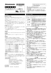
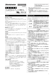
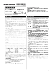
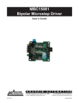
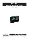
ACP-MxI Series, AC Induction Motor
User’s Manual
• Brushless design for long life and quiet operation
• 110/220 VAC input
• Single or Three phase input available
• Rated for Continuous operation
• High power factor up to 0.8
• Self starting
• UL Certified
• Output from 6 to 150 watts
• High Starting torque for high inertial loads.
• Direct Replacement for some Panasonic AC induction motors
Figure 1: Optional Gearbox and Fan
attached
The ACP-MxI Series are fractional horsepower induction motors.
ACP-MxI series provide users that need a simple solution. The ACP-MxI offers different sizes to accommodate
your needs. These AC Induction motors can be customized to have a clutch and/or brake. ACP-MxI series
operate at 120 or 220VAC, so there is no need for a transformer, just hook up and go! ACP-MxI series AC
Induction motors can also be mated with other accessories, another reason to choose Anaheim Automation for
your AC induction motor projects.
ACP-MxI series can be tailored with three phase AC Input.Three phase AC Induction motors are used when
efficiency needs to be at its highest. A benefit of having a three phase AC induction motor is without the need of
a starting capacitor. Our three phase AC induction motors offer great starting torque compared to other three
phase AC induction motors.
Figure 2: ACP-MxI typical torque speed curve
A N A H E I M
A U T O M A T I O N
910 East Orangefair Lane, Anaheim, CA 92801
e-mail: [email protected]
#L010583
(714) 992-6990 fax: (714) 992-0471
website: www.anaheimautomation.com
August 2009
Hook-Up Drawing
Figure 3: Induction Motor Hookup, Single Phase
Recommended Capacitor Values
Part Number
uF
Voltage
ACP-M-2IK6A-AU
2.5
ACP-M-3IK15A-AU
Part Number
uF
Voltage
250
ACP-M-2IK6A-CU
.8
450
4
250
ACP-M-3IK15A-CU
1
450
ACP-M-4IK25A-AU
6
250
ACP-M-4IK25A-CU
1.5
450
ACP-M-5IK40A-AU
8
250
ACP-M-5IK40A-CU
2
450
ACP-M-5IK60A-AFU
16
250
ACP-M-5IK60A-CFU
4
450
ACP-M-5IK90A-AFU
20
250
ACP-M-5IK90A-CFU
5
450
ACP-M-5IK120A-AF
25
250
ACP-M-5IK120A-CF
7
450
ACP-M-5IK150A-AF
36
250
ACP-M-5IK150A-CF
8
450
Table 1: Capacitor Specifications
Power Supply Requirements
It is recommended that the ACP-MxI series be powered by 120 VAC for the ACP-M-xIxxx-Ax or 220 VAC for
the ACP-M-xIxxx-Cx series
Absolute Maximum Ratings
Input Voltage for ACP-M-xIxxx-Ax: 130 VAC
Input Voltage for ACP-M-xIxxx-Cx: 240 VAC
Max Case Temperature: 80° C
Storage Temperature: 0° to +50° C
#L010583
Temperature consideration: Use additional airflow and/or heatsinking
to keep motor temperature under 80° C.
August 2009
Specifications
Part Number
Poles
No
Load
Spe ed
(RPM)
ACP‐M‐2IK6A‐AU
ACP‐M‐3IK15A‐AU
ACP‐M‐4IK25A‐AU
ACP‐M‐5IK40A‐AU
ACP‐M‐5IK60A‐AFU
ACP‐M‐5IK90A‐AFU
ACP‐M‐5IK120A‐AFU
ACP‐M‐5IK150A‐AFU
4
4
4
4
4
4
4
4
1800
1800
1800
1800
1800
1800
1800
1800
1550
1600
1500
1575
1550
1625
1610
1512
0.41
0.59
0.91
1.5
2.2
3.1
2.85
3.3
0.25
0.34
0.49
0.74
1.06
1.7
1.65
2.61
5.7
12.5
19.4
33.3
62.5
66
107
126.4
7.2
12.5
25
37.5
52.7
73.6
101
137.5
14.4
25
50
75
105.4
147.2
202
275
ACP‐M‐2IK6A‐CU
ACP‐M‐3IK15A‐CU
ACP‐M‐4IK25A‐CU
ACP‐M‐5IK40A‐CU
ACP‐M‐5IK60A‐CFU
ACP‐M‐5IK90A‐CFU
ACP‐M‐5IK120A‐CFU
ACP‐M‐5IK150A‐CFU
4
4
4
4
4
4
4
4
1800
1800
1800
1800
1800
1800
1800
1800
1550
1600
1625
1590
1550
1625
1615
1560
0.21
0.3
0.55
0.75
1.1
1.6
1.52
1.7
0.13
0.17
0.24
0.31
0.54
0.85
0.92
1.07
5.7
12.5
19.4
33.3
62.5
66
119
130
7.2
12.5
25
37.5
52.7
73.6
104
130
14.4
25
50
75
105.4
147.2
208
260
ACP‐M‐4IK25A‐SU
ACP‐M‐5IK40A‐SU
ACP‐M‐5IK60A‐SFU
ACP‐M‐5IK90A‐SFU
ACP‐M‐5IK120A‐SFU
ACP‐M‐5IK150A‐SFU
4
4
4
4
4
4
1800
1800
1800
1800
1800
1800
1650
1675
1675
1675
1600
1570
0.52
1
1.4
2.1
2.6
3.1
0.19
0.27
0.4
0.56
0.8
1
54
91
119
208
312
336
20
32
48.6
73.6
104
132
60
96
145.8
220.8
312
396
#L010583
Rated
Load
Speed
(RPM)
Sta rting Rated
Current Current
(A)
(A)
Starting
Torque
(oz-in)
Rated Maximum
Torque
Torque
(oz-in)
(oz-in)
August 2009
Dimensions
Figure 4: Dimensions for ACP-M-2IK6A-(A)(C)UV
Figure 5: Dimensions for ACP-M-3IK15A-(A)(C)UV
Figure 6: Dimensions for ACP-M-4IK25A-(A)(C)UV
#L010583
August 2009
Dimensions
Figure 7: Dimensions for ACP-M-5IK40A-(A)(C)UV
Figure 8: Dimensions for ACP-M-5IK60A-(A)(C)FUV
Figure 9: Dimensions for ACP-M-5IK90A-(A)(C)FUV, ACP-M-5IK120A-(A)(C)FUV, ACP-M-5IK150A-(A)(C)FUV
#L010583
August 2009
AC Induction Motor FAQ
What happens if I remove the internal brake mechanism of an AC induction reversible motor? Can I
then use it as a regular AC induction motor?
An AC reversible motor is an AC induction motor, but is made different. An AC reversible motor has its
coils wound specifically for the application of a quick reversal movement. The AC reversible motor has its
primary and secondary coils altered. Having a different ratio between the primary and secondary coils, its
starting torque characteristics will be changed. This change makes it have the instant reversing characteristics.
Moreover, the capacitor has been changed also to increase the starting torque. Therefore, removing just the
internal brake mechanism won’t help make the reversible motor run continuously.
Why do AC induction reversible motors have a 30 minute rating?
Due to the construction and the purpose of the AC reversible motor, it won’t allow running more than 30
minutes. The reason being is that a reversible motor requires a higher input power than an AC induction motor.
The higher input power is used for the increased starting torque and instant reversing characteristics. There are
higher losses in an reversible motor than a regular AC induction motor. Running the motor for more than 30
minutes can cause the motor to burn up. Therefore, for maximum performance, it is recommended for 30
minutes of use at a time.
Can I run an AC induction reversible motor longer than 30 minutes?
You can increase the running time of the motor if heating considerations are taken care of. The motor
casing should be below 80 degrees Centigrade.
Can I run an AC induction reversible motor 30 minutes in one direction then 30 minutes in the other?
The 30 minute rating is for the total time that the motor is on, regardless of direction.
Can I use a solid state relay (SSR) to switch the direction?
When using a SSR to switch direction, please allow at minimum of 100ms before switching to the other
direction.
Can I use a capacitor other than the one it came with?
The capacitor that came with the motor was chosen for optimum stability and performance. When using
another capacitor, use the recommended capacitance and voltage values when obtaining another capacitor.
The use of non polarized capacitors should be used. For example, Electrolytic capacitors should not be used.
What happens if I use a different capacitor value other what has been given?
When using a different capacitor value, the AC induction motor may or may not start up. Erratic startup
can also occur when using different capacitor values.
#L010583
August 2009
How does power supply fluctuation affect AC induction motor?
The fluctuations of voltage will affect the torque output of the motor. The torque developed by an AC
induction motor is proportional to the square of the applied voltage.
For example:
Rated voltage:100VAC
Stall Torque,Tm: .5 N·m
Starting Torque,Ts: .25 N·m
The voltage is then reduced to 75VAC:
New Tm:[.5*(75/100)^2 ]=.375 N·m
New Ts:[.25*(75/100)^2 ]=.1875 N·m
If the motor is going to experience power fluctuations, please take it into account when choosing an AC induction motor.
COPYRIGHT
Copyright 2007 by Anaheim Automation. All rights reserved. No part of this publication may be reproduced,
transmitted, transcribed, stored in a retrieval system, or translated into any language, in any form or by any
means, electronic, mechanical, magnetic, optical, chemical, manual, or otherwise, without the prior written
permission of Anaheim Automation, 910 E. Orangefair Lane, Anaheim, CA 92801.
DISCLAIMER
Though every effort has been made to supply complete and accurate information in this manual, the
contents are subject to change without notice or obligation to inform the buyer. In no event will Anaheim
Automation be liable for direct, indirect, special, incidental, or consequential damages arising out
of the use or inability to use the product or documentation.
Anaheim Automation’s general policy does not recommend the use of its’ products in life support applications
wherein a failure or malfunction of the product may directly threaten life or injury. Per Anaheim Automation’s
Terms and Conditions, the user of Anaheim Automation products in life support applications assumes all
risks of such use and indemnifies Anaheim Automation against all damages.
LIMITED WARRANTY
All Anaheim Automation products are warranted against defects in workmanship, materials and construction,
when used under Normal Operating Conditions and when used in accordance with specifications. Warranty
provisions may be voided if products are subjected to physical modifications, damage, abuse, or
misuse.
Anaheim Automation will repair or replace at its’ option, any product which has been found to be defective
and is within the warranty period, provided that the item is shipped freight prepaid, with previous authorization
(RMA#) to Anaheim Automation’s plant in Anaheim, California.
TECHNICAL SUPPORT
If you should require technical support or if you have problems using any of the equipment covered by this
manual, please read the manual completely to see if it will answer the questions you have. If you need
assistance beyond what this manual can provide, contact your Local Distributor where you purchased the
unit, or contact the factory direct.
ANAHEIM AUTOMATION
#L010583
August 2009