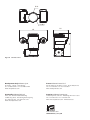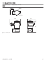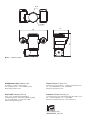
1
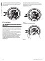
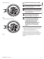
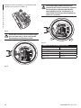
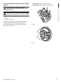
MAXIMUS MPX,
MAXIMUS MPXT
Explosion proof stainless steel PTZ positioning system
EN English - Instructions manual
JA 日本語 - 取扱説明書
MAXIMUS MPX,
MAXIMUS MPXT
Explosion proof stainless steel PTZ positioning system
"IP model isn’t certified by TIIS yet."
EN English - Instructions manual
Contents
ENGLISH
1.1 Typographical conventions................................................................................................................................... 7
2 Notes on copyright and information on trademarks................................................... 7
3 Safety rules..................................................................................................................... 7
4 Identification................................................................................................................... 9
4.1 Product description and type designation..................................................................................................... 9
4.1.1 Version for thermal imaging cameras.............................................................................................................................10
5 Preparing the product for use..................................................................................... 11
5.1 Safety precautions before use............................................................................................................................11
5.2 Unpacking and contents......................................................................................................................................12
5.2.1 Unpacking.................................................................................................................................................................................12
5.2.2 Contents.....................................................................................................................................................................................12
5.3 Safely disposing of packaging material..........................................................................................................12
5.4 Preparatory work before installation...............................................................................................................13
5.4.1 Fixing to parapet or ceiling mount..................................................................................................................................13
5.4.2 Fixing with bracket.................................................................................................................................................................14
5.4.3 Fixing the unit to the pole mount adapter or corner mount adapter.................................................................14
5.4.3.1 Fixing with pole mount.............................................................................................................................................................................14
5.4.3.2 Fixing with corner adapter.......................................................................................................................................................................15
5.4.4 Fixing the sunshield...............................................................................................................................................................15
6 Assembling and installing........................................................................................... 16
6.1 Installation.................................................................................................................................................................16
6.1.1 Range of use.............................................................................................................................................................................16
6.1.2 Methods of installation........................................................................................................................................................16
6.1.3 Connecting the cables to the base..................................................................................................................................17
6.1.4 Cable entry................................................................................................................................................................................18
6.1.5 Connection of the power supply line..............................................................................................................................19
6.1.6 Connections of one or more video cables.....................................................................................................................21
6.1.7 Connection of the Ethernet cable....................................................................................................................................22
6.1.8 Telemetry line connections.................................................................................................................................................23
6.1.9 Alarm and relay connections.............................................................................................................................................24
6.1.9.1 Connecting an alarm with clean contact (dry contact).................................................................................................................24
6.1.9.2 Relay connection.........................................................................................................................................................................................24
6.1.10 Unit address, communication protocol and baud rate setting...........................................................................25
6.1.11 Configuration of the dip-switches.................................................................................................................................25
6.1.12 Setting the configuration check mode........................................................................................................................25
6.1.13 Baud rate configuration.....................................................................................................................................................26
6.1.14 Setting of the serial communication lines..................................................................................................................26
6.1.14.1 Two-way RS-485 TX/RX line...................................................................................................................................................................27
6.1.14.2 Line RS-485-1 reception, line RS-485-2 repetition........................................................................................................................27
6.1.14.3 Two-way RS-422 line................................................................................................................................................................................27
6.1.14.4 One-way RS-485 line................................................................................................................................................................................27
6.1.15 Serial line terminations and connections....................................................................................................................28
6.1.16 Protocol configuration.......................................................................................................................................................28
MNVCMPXTJP_1415_EN
3
Instructions manual - English - EN
1 About this manual.......................................................................................................... 7
EN - English - Instructions manual 6.1.17 Address configuration........................................................................................................................................................28
6.1.18 Earth wiring connection....................................................................................................................................................29
6.1.19 Connection compartment closing................................................................................................................................29
7 Instructions for safe operation.................................................................................... 30
7.1 Safe operation..........................................................................................................................................................30
7.1.1 Commissioning.......................................................................................................................................................................30
7.1.2 Safety rules................................................................................................................................................................................31
7.1.3 Explosion prevention rules.................................................................................................................................................31
8 Switching on................................................................................................................. 31
8.1 Before powering the product in an explosive atmosphere....................................................................31
9 Configuration................................................................................................................ 32
9.1 Using the OSM.........................................................................................................................................................32
9.1.1 How to use the joystick........................................................................................................................................................32
9.2 How to move around the menus......................................................................................................................32
9.3 How to change the settings................................................................................................................................33
9.4 How to change the numeric fields...................................................................................................................33
9.5 How to change text...............................................................................................................................................34
9.6 Configuration via OSM..........................................................................................................................................35
9.6.1 Main menu................................................................................................................................................................................35
9.6.2 Language...................................................................................................................................................................................35
9.6.3 Camera menu...........................................................................................................................................................................35
9.6.3.1 Zone Titling Menu.......................................................................................................................................................................................36
9.6.3.2 Zone Titling Menu (Edit Area)..................................................................................................................................................................36
9.6.3.3 Masking Menu..............................................................................................................................................................................................37
9.6.3.4 Masking Menu (Edit Masks).....................................................................................................................................................................38
9.6.3.5 How to create a new mask.......................................................................................................................................................................38
9.6.3.6 How to modify a mask...............................................................................................................................................................................39
9.6.3.7 Advanced Setting Menu...........................................................................................................................................................................40
9.6.3.8 Advanced Setting Menu (Zoom)............................................................................................................................................................40
9.6.3.9 Advanced Setting Menu (Focus)............................................................................................................................................................41
9.6.3.10 Advanced Setting Menu (Exposure)...................................................................................................................................................41
9.6.3.11 Advanced Setting Menu (Infrared).....................................................................................................................................................42
9.6.3.12 Advanced Setting Menu (White Balance)........................................................................................................................................43
9.6.3.13 Advanced Setting Menu (Other)..........................................................................................................................................................44
9.6.4 Movement Menu....................................................................................................................................................................44
9.6.4.1 Manual Control Menu................................................................................................................................................................................45
9.6.4.2 Manual Control Menu (Limits)................................................................................................................................................................45
9.6.4.3 Preset Menu...................................................................................................................................................................................................45
9.6.4.4 Preset Menu (Edit Preset)..........................................................................................................................................................................46
9.6.4.5 Preset Menu (Utility Preset)......................................................................................................................................................................46
9.6.4.6 Patrol Menu....................................................................................................................................................................................................47
9.6.4.7 Autopan Menu..............................................................................................................................................................................................47
9.6.4.8 Motion Recall Menu....................................................................................................................................................................................47
9.6.4.9 Advanced Menu...........................................................................................................................................................................................48
9.6.5 Display Menu...........................................................................................................................................................................48
9.6.6 Options Menu..........................................................................................................................................................................49
9.6.6.1 Alarms Menu.................................................................................................................................................................................................49
9.6.7 Washer Menu...........................................................................................................................................................................50
9.6.8 Default Menu...........................................................................................................................................................................50
9.6.9 Info Menu..................................................................................................................................................................................50
4
MNVCMPXTJP_1415_EN
9.6.10 Thermal Camera Menu.......................................................................................................................................................51
9.7 Configuration of the version with IP board...................................................................................................57
9.7.1 Minimum system requirements........................................................................................................................................57
9.7.2 Configuration procedure through software.................................................................................................................57
9.7.2.1 WAN setting...................................................................................................................................................................................................58
9.7.3 Installing the NVR software.................................................................................................................................................60
9.7.3.1 Controlling PTZ movements....................................................................................................................................................................62
9.7.3.2 Preset and load positions..........................................................................................................................................................................63
10 Instructions for safe operation.................................................................................. 64
10.1 Visualizing the state of the pan & tilt.............................................................................................................64
10.2 Saving the current position (Preset)..............................................................................................................65
10.2.1 Quick save...............................................................................................................................................................................65
10.2.2 Saving from the Menu........................................................................................................................................................65
10.3 Recalling a position (Scan)................................................................................................................................65
10.4 Enabling the patrol (Patrol)...............................................................................................................................65
10.5 Enabling Autopan Function.............................................................................................................................65
10.6 Recalling a pattern (Tour)..................................................................................................................................65
10.7 Recalling the Home position............................................................................................................................66
10.8 Enabling the wiper (Wiper)...............................................................................................................................66
10.9 Enabling the washer...........................................................................................................................................66
10.10 Reboot the device.............................................................................................................................................66
10.11 Manual correction of a preset focusing.....................................................................................................67
10.12 Special controls..................................................................................................................................................67
11 Maintaining and cleaning.......................................................................................... 69
11.1 System configuration and statistics display...............................................................................................69
11.2 Maintenance and cleaning by users..............................................................................................................69
11.2.1 Routine (to be carried out regularly).............................................................................................................................69
11.2.1.1 Cleaning the glass.....................................................................................................................................................................................69
11.2.1.2 Cleaning the germanium window......................................................................................................................................................69
11.2.1.3 Cleaning the device..................................................................................................................................................................................69
11.2.1.4 Inspecting the cables...............................................................................................................................................................................69
11.2.2 Extraordinary (to be done only under particular circumstances)......................................................................70
12 Disposal of waste materials....................................................................................... 70
13 Troubleshooting......................................................................................................... 71
14 Technical data............................................................................................................. 73
14.1 MPX...........................................................................................................................................................................73
14.1.1 General.....................................................................................................................................................................................73
14.1.2 Mechanical.............................................................................................................................................................................73
MNVCMPXTJP_1415_EN
5
Instructions manual - English - EN
9.6.10.1 Flat Field Correction Menu.....................................................................................................................................................................52
9.6.10.2 Flat Field Correction Menu (Gain Switch Values)...........................................................................................................................53
9.6.10.3 Video Setup Menu.....................................................................................................................................................................................53
9.6.10.4 Gain Control Menu...................................................................................................................................................................................54
9.6.10.5 ROI Setup Menu.........................................................................................................................................................................................55
9.6.10.6 Thermal Analysis Menu...........................................................................................................................................................................55
9.6.10.7 Thermal Analysis Menu (Spot Meter).................................................................................................................................................55
9.6.10.8 Thermal Analysis Menu (Isotherm).....................................................................................................................................................56
9.6.10.9 Status Menu................................................................................................................................................................................................56
EN - English - Instructions manual 14.1.3 Electrical/Video.....................................................................................................................................................................73
14.1.4 Communications..................................................................................................................................................................74
14.1.5 Protocols..................................................................................................................................................................................74
14.1.6 Environment..........................................................................................................................................................................74
14.1.7 Brackets and adapters........................................................................................................................................................74
14.1.8 Package....................................................................................................................................................................................74
14.2 MPXT.........................................................................................................................................................................74
14.2.1 General.....................................................................................................................................................................................74
14.2.2 Mechanical.............................................................................................................................................................................74
14.2.3 Electrical/Video.....................................................................................................................................................................74
14.2.4 Communications..................................................................................................................................................................75
14.2.5 Protocols..................................................................................................................................................................................75
14.2.6 Environment..........................................................................................................................................................................75
14.2.7 Brackets and adapters........................................................................................................................................................75
14.2.8 Package....................................................................................................................................................................................75
14.3 Electrical rating.....................................................................................................................................................75
14.4 Camera.....................................................................................................................................................................76
15 Technical drawings..................................................................................................... 81
6
MNVCMPXTJP_1415_EN
1 About this manual
3 Safety rules
The manufacturer declines all responsibility
for any damage caused by an improper use
of the appliances mentioned in this manual.
Furthermore, the manufacturer reserves
the right to modify its contents without any
prior notice. The documentation contained
in this manual has been collected with great
care, the manufacturer, however, cannot
take any liability for its use. The same thing
can be said for any person or company
involved in the creation and production of
this manual.
1.1 Typographical conventions
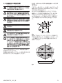
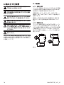
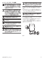
DANGER!
Explosion hazard.
Read carefully to avoid danger of explosion.
DANGER!
High level hazard.
Risk of electric shock. Disconnect the
power supply before proceeding with any
operation, unless indicated otherwise.
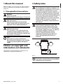
This device must be connected to an
earth conductor (protective earth). This
connection must be made only throught
the internal connector J1 (6.1.5 Connection
of the power supply line, page 19). External
equipotential bonding connections
must also be performed but only for
supplementary bonding connection to
earth, and required by local codes or
authority.
WARNING!
Medium level hazard.
This operation is very important for the
system to function properly. Please read
the procedure described very carefully and
carry it out as instructed.
INFO
Description of system specifications.
We recommend reading this part carefully
in order to understand the subsequent
stages.
2 Notes on copyright and
information on trademarks
The quoted names of products or companies are
trademarks or registered trademarks.
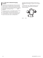
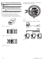
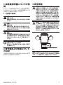
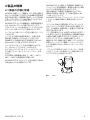
Fig. 1
External hole for Equipotential bonding
required by authority. Not to be intended as
protective earth connections.
MNVCMPXTJP_1415_EN
7
Instructions manual - English - EN
Before installing and using this unit, please read this
manual carefully. Be sure to keep it handy for later
reference.
• Read these instructions.
• Keep these instructions.
EN - English - Instructions manual • Heed all warnings.
• Follow all instructions.
• This device is remotely controlled and may change
position at any time. It should be installed so that
no one can be hit by moving parts. It should be
installed so that moving parts cannot hit other
objects and create hazardous situations.
• To reduce the risk of ignition of hazardous
atmospheres, disconnect the equipment from the
supply circuit before opening. Keep the product
tightly closed when in operation.
• Make sure that the device is firmly anchored.
• The equipment is certified for use in ambient
temperatures from -40°C to +60°C (from -40°F to
+140°F).
• The connection compartment lid can be opened
only for cabling the device. The other lids must be
open from the manufacturer.
• Installation of this equipment shall be carried out
by suitably trained personnel in accordance with
the applicable code of practice IEC/EN 60079-14.
• The temperature of the surfaces of the device
is increased by exposure to direct sunlight. The
surface temperature class of the device was
determined only with ambient air temperature,
without taking into consideration direct sunlight.
• A power disconnect device must be included
in the electrical installation, and it must be very
quickly recognizable and operated if needed.
• Do not use cables that seem worn or old.
• For technical services, consult only and exclusively
authorized technicians.
• Choose an installation surface that is strong
enough to sustain the weight of the device, also
bearing in mind particular environmental aspects,
such as exposure to strong winds.
• Since the user is responsible for choosing the
surface to which the unit is to be anchored, we
do not supply the fixing devices for attaching the
unit firmly to the particular surface. The installer is
responsible for choosing fixing devices suitable for
the specific purpose on hand. Use methods and
materials capable of supporting at least 4 times the
weight of the device.
8
MNVCMPXTJP_1415_EN
4 Identification
The MAXIMUS series explosion-proof pan-tiltzoom (PTZ) camera positioning devices have been
designed to allow movement, on both a horizontal
and a vertical plane of a in-built camera and to
operate in industrial environments in which there
may be an explosive atmosphere due to gas, vapours,
mists, or air or powder mixtures.
MAXIMUS PTZ devices, supplied complete with an in
built camera, are made of AISI 316L electropolished
stainless steel.
This unit basically consists of a base, a main body and
a housing for the camera.
Versions with a second housing for thermal cameras
are available.
On the base there is a connection compartment
that allows very easy cabling of the system, and it
comprises the power supply electronics. There is a
hole 3/4” NPT on the base and the connection must
to be done in conformity with IEC/EN60079-14.
The main body contains the motors for horizontal
and vertical movements and the CPU and video
boards.
Speed and precision are the predominant pan-andtilt characteristics, reaching 100°/s in continuous
horizontal rotation, with vertical range between -90°
to +90°.
MAXIMUS PTZ manages the preset, auto-pan and
patrol functions with an accuracy 0.02°.
The unit performs a continuous control of its position
to verify the correct positioning of the camera at any
time. This is a very useful function in case of severe
environmental conditions, such as strong wind and
heavy vibrations.
The choice of integrated SONY cameras offer 36x
and 28x zoom lenses, which allow the recording with
exceptional precision of both close-by and far away
objects, as well dynamic privacy zone masking.
Besides the OSD (On Screen Display) configuration,
the system is equipped with an RS485 interface for
complete system control and for the updating in
remote mode of the latest firmware version.
The simplified set-up software interface offers typical
preset configurations or the possibility to customize
the complete system.
The camera housing contains a day/night module
with its electronics, an heater and a built-in wiper.
The PTZ device has an IP66 protection degree and
its operating temperature is - 40°C to 60°C (-40°F /
140°F).
MAXIMUS PTZ includes integrated high-performance
pan-and-tilt telemetry.
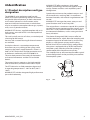
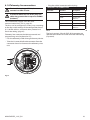
Fig. 2MPX.
MNVCMPXTJP_1415_EN
9
Instructions manual - English - EN
4.1 Product description and type
designation
MAXIMUS PTZ offers continuous, high speed
rotation, positioning precision and superior image
quality, utmost sturdiness and simplified system
configuration.
EN - English - Instructions manual 4.1.1 Version for thermal imaging
cameras
The device can be provided with a thermal imaging
camera, which is installed inside a second housing,
whose window is made mainly of germanium which
guarantees the same strength and security properties
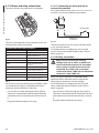
as those for standard glass (Fig. 3
MPXT.,
page 10).
The high sensitivity NEdT 50mK at f/1.0 ensures an
optimal thermal imaging. It supports 2x or 4x digital
zoom.
A choice of lens sizes is offered between 35mm,
25mm and 9mm, depending on the detection
distance required.
The thermal camera is an Uncooled Vanadium Oxide
microbolometer (VOx) with spectral band 7.513.5μm. It delivers a thermal video of 320x 256 (PAL)
and 320x240 (NTSC), with an image frequency of
8.3fps or 25 fps (PAL) and 7.5 or 30fps (NTSC).
Fig. 3MPXT.
10
MNVCMPXTJP_1415_EN
Any change that is not expressly approved
by the manufacturer will invalidate both
the guarantee and certification.
Before installation, make sure the power
supply and protection specifications of the
device correspond to those in the original
order. Use of unsuitable appliances can
cause serious hazards, risking the safety of
personnel and of the installation.
5.1 Safety precautions before use
The electrical installation in which the
unit is inserted must be equipped with a
15A maximum bipolar protection circuit
(magnetothermal), that must include a
bipolar automatic-type circuit breaker,
which must also envisage earth fault
current protection (magnetothermal +
differential) with minimum distance of
3mm between contacts.
Make sure that all the devices are certified
for the application and for the environment
in which they will be installed.
MNVCMPXTJP_1415_EN
The device can only be considered to be
switched off when the power supply has
been disconnected and the connection
cables to other devices have been removed.
A power disconnect device must be
included in the electrical installation, and
it must be very quickly recognizable and
operated if needed.
Before doing any technical work on the
device make sure that the power supply is
disconnected.
Make connections and tests in the
laboratory before carrying out installation
on site. Use appropriate tools for the
purpose.
Before proceeding with any operations,
make sure that the mains voltage is correct.
For handling there aren’t request of
particular demands to assigned staff,
therefore it is recommended, to carry out
such operation observing the common
rules of accident prevention.
11
Instructions manual - English - EN
5 Preparing the product for
use
5.2 Unpacking and contents
EN - English - Instructions manual 5.2.1 Unpacking
When the product is delivered, make sure that the
package is intact and that there are no signs that it
has been dropped or scratched.
If there are obvious signs of damage, contact the
supplier immediately.
Keep the packaging in case you need to send the
product for repairs.
5.3 Safely disposing of packaging
material
The packaging material can all be recycled. The
installer technician will be responsible for separating
the material for disposal, and in any case for
compliance with the legislation in force where the
device is to be used.
When returning a faulty product we recommend
using the original packaging for shipping.
5.2.2 Contents
Check the contents to make sure they correspond
with the list of materials as below:
Analog version:
• 1 explosion-proof P&T
• 1 sunshield (2 if version with thermal camera)
• 1 document Important safety instructions
• 1 sheath
• 2 ties
• 2 hexagon socket set screws
• Instructions manual
IP version:
• 1 explosion-proof P&T
• 1 sunshield (2 if version with thermal camera)
• 1 document Important safety instructions
• 1 sheath
• 2 ties
• 2 hexagon socket set screws
• 1 CD
• Instructions manual
12
MNVCMPXTJP_1415_EN
5.4 Preparatory work before
installation
Choose an installation surface that is
strong enough to sustain the weight of
the device, also bearing in mind particular
environmental aspects, such as exposure to
strong winds.
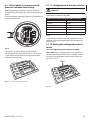
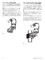
Attach the adapter (01) to the bottom of the unit
using 4 stainless steel (A4 class 80) socket flat head
cap screw M10 x 20mm (02).
Make sure the thread are free of dirt and debris.
Apply a generous amount of thread locking
compound (Loctite 270) into the threaded holes in
the base of the device.
Tighten them to 35Nm. The thread compound
must cure for one hour, allow for this period prior to
completing the installation.
02
01
It should be installed so that no one can be
hit by moving parts. It should be installed
so that moving parts cannot hit other
objects and create hazardous situations.
Make sure that the device is firmly
anchored.
Use the external holes in the adapter to fix the
assembled unit to the wall or to the pole. Use screws
that can bear at least 4 times the weight of the unit.
00
35
35
Since the user is responsible for choosing
the surface to which the unit is to be
anchored, we do not supply the fixing
devices for attaching the unit firmly to
the particular surface. The installer is
responsible for choosing fixing devices
suitable for the specific purpose on hand. In
general use methods and materials capable
of supporting at least four times the weight
of the device.
35
35
For technical services, consult only and
exclusively authorized technicians.
Fig. 4
Ø2
The device must be installed and
maintained only and exclusively by
qualified technical personnel.
8
Ø 11
It is possible to install the unit with several brackets.
We strongly recommend using only approved
brackets and accessories during installation.
Ø 238
Fig. 5
MNVCMPXTJP_1415_EN
13
Instructions manual - English - EN
Use appropriate tools for the installation.
The particular nature of the site where the
device is to be installed may mean special
tools are required for installation.
5.4.1 Fixing to parapet or ceiling mount
EN - English - Instructions manual 5.4.2 Fixing with bracket
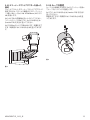
The bracket can be fixed to the vertical wall. Use
screws and wall fixing devices that can bear at least
four times the weight of the unit.
To fix the device to the bracket, use 4 washers, 4
stainless steel grower washer and 4 hexagon stainless
steel bolts (A4 class 80) M10x20mm.
Make sure the thread are free of dirt and debris.
Apply a generous amount of thread locking
compound (Loctite 270) into the threaded holes in
the base of the device.
Tighten them to 35Nm. The thread compound
must cure for one hour, allow for this period prior to
completing the installation.
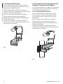
5.4.3 Fixing the unit to the pole mount
adapter or corner mount adapter
To install the component on a pole or at a wall corner,
first of all fix the pan & tilt unit to the wall bracket (
5.4.2 Fixing with bracket, page 14).
5.4.3.1 Fixing with pole mount
Fix the wall bracket to the pole mount adapter
using 4 washers, 4 stainless steel grower washer
and 4 hexagon stainless steel bolts (A4 class 80)
M10x30mm.
Make sure the thread are free of dirt and debris.
Apply a generous amount of thread locking
compound (Loctite 270) into the threaded holes in
the base of the device.
Tighten them to 35Nm. The thread compound
must cure for one hour, allow for this period prior to
completing the installation.
Fig. 6
Fig. 7
14
MNVCMPXTJP_1415_EN
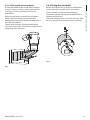
5.4.4 Fixing the sunshield
Fix the wall bracket to the corner mount adapter
using 4 washers, 4 stainless steel grower washers
4 hexagon stainless steel bolts (A4 class 80)
M10x30mm.
Before running the wiring, fix the sunshield to the
camera housing using the screws and washers.
Make sure the thread are free of dirt and debris.
Apply a generous amount of thread locking
compound (Loctite 270) into the threaded holes in
the base of the device.
Apply a generous amount of thread locking
compound (Loctite 270) into the threaded holes in
the base of the device.
The thread compound must cure for one hour, allow
for this period prior to completing the installation.
Tighten them to 35Nm. The thread compound
must cure for one hour, allow for this period prior to
completing the installation.
Fig. 9
Fig. 8
MNVCMPXTJP_1415_EN
15
Instructions manual - English - EN
5.4.3.2 Fixing with corner adapter
6 Assembling and installing
EN - English - Instructions manual Make all installation works and connections
in a non-explosive atmosphere.
Make sure that all the devices are certified
for the application and for the environment
in which they will be installed.
The following procedures should be carried
out with the power supply disconnected,
unless indicated otherwise.
The device must be installed only
and exclusively by qualified technical
personnel.
At start up the system makes some
automatic calibration movements: do not
stand near the device when it is powered.
Make sure that the installation complies
with local regulations and specifications.
Videotec strongly recommend to test the device
configuration and performance in a office\laboratory
before putting it in the final installation site. (6.1.3
Connecting the cables to the base, page 17).
6.1 Installation
6.1.1 Range of use
The unit is designed for use in a fixed location, for
surveillance of areas classified as zone 1-21 and zone
2-22 potentially explosive atmospheres, using its
embedded cameras.
The installation temperature range is -40°C to 60°C
(-40°F/140°F).
The device is operative from-40°C to 60°C
(-40°F/140°F).
The equipment has not been assessed as a safety
related device (as referred to by Directive 94/9/EC
Annex II, clause 1.5).
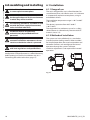
6.1.2 Methods of installation
The system can be installed only in a standard or
inverted position (ceiling mount). When installed
for inverted operation, the camera orientation and
controller functions are reconfigured for normal
operation through the system’s software.
Hardware adjustment is not required for inverted
operation.
Fig. 10
16
MNVCMPXTJP_1415_EN
6.1.3 Connecting the cables to the base
The electrical installation in which the
unit is inserted must be equipped with a
15A maximum bipolar protection circuit
(magnetothermal), that must include a
bipolar automatic-type circuit breaker,
which must also envisage earth fault
current protection (magnetothermal +
differential) with minimum distance of
3mm between contacts.
A power disconnect device must be
included in the electrical installation, and
it must be very quickly recognizable and
operated if needed.
Before doing any technical work on the
device make sure that the power supply is
disconnected.
The connection compartment lid can
be opened only for cabling the device.
The other lids must be open from the
manufacturer.
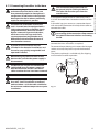
A connection compartment for cable entry with a
3/4” NPT threaded hole is located on the base of the
unit.
A threaded cap gives access to a connection board
with removable connectors that help the installer to
connect the cables.
An hexagon set screw is used to prevent the
unscrewing of the connection compartment
threaded lid. Remove it before unscrewing
the lid.
Refer to the following images and information to
connect the wires and cables as required.
To connect the positioning unit remove the hexagon
socket set screw, the plastic cap and the threaded
cover.
The plastic cap thread is available only for shipping
and cannot be used for operation.
The device can only be considered to be
switched off when the power supply has
been disconnected and the connection
cables to other devices have been removed.
Do not use worn or old power cables.
Use adequate cable for higher temperature
than 80°C. And if installed in an external
ambient below –10°C the cable suitable for
the minimum ambient temperature at point
installation.
MNVCMPXTJP_1415_EN
Fig. 11
17
Instructions manual - English - EN
Before doing any technical work or
maintenance on the device, make sure
that potentially explosive atmosphere is
not present. To reduce the risk of ignition
don’t open the device when a potentially
explosive atmosphere is present.
To make the wirings, unplug the removable
connector from the connection board, cable all the
conductors on it and then plug the flying connector
on the board as shown.
Telemetry wiring.
FUS
E
FUS2
FUS1
ADDRESS & PROTOCOL
VIDEO - 1
VAR1
FUS
E
J4
J9
J6
A
B
A
VIDEO - 2
B
GND
W
GND
AC IN
J3
J8
J2
L
N
FUS1
VAR1
J9
J6
A
B
A
VIDEO - 2
B
GND
W
GND
AC IN
J7
J1
L
FUS
E
100nMBW3
N
VAR2
VAR3
VIDEO - 1
RL2
RL2
RL1
RL1
COM
AL5
AL4
AL3
AL2
AL1
J7
J1
FUS
E
FUS2
RS485
RL2
RL2
RL1
RL1
COM
AL5
AL4
AL3
AL2
AL1
RS485
J3
J8
J2
VAR2
VAR3
100nMBW3
Fig. 12
Only MPXT series have 2 coax cable video
output.
Fig. 13
Take the J9 removable connector.
To prevent the passage of flames or explosions from
the unit to the conduit system or cable gland to the
external environment, use connection in conformity
with IEC/EN60079-14.
ADDRESS & PROTOCOL
FUS
J4
E
J2
All cable gland devices shall be certified in type of
explosion protection “d” and/or "tb", suitable for the
conditions of use and correctly installed.
J3
J8
FUS2
RL2
RL2
RL1
RL1
COM
AL5
AL4
AL3
AL2
AL1
FUS1
VAR1
VIDEO - 1
J9
J6
A
VIDEO - 2
B
GND
W
GND
L
N
E
VAR3
J7
AC IN J1
FUS
When conduit is used, a suitable certified stopping
box, in type of explosion protection “d” and/or "tb",
suitable for the conditions of use and correctly
installed. Being fitted within 25mm (1in) from the
enclosure wall.
A
B
RS485
6.1.4 Cable entry
VAR2
EN - English - Instructions manual Inside the connection compartment you'll find an
address and protocol board and a connectors board
with removable connectors that make the cabling
procedure easy.
100nMBW3
Fig. 14
18
MNVCMPXTJP_1415_EN
6.1.5 Connection of the power supply
line
Cable the wires on it.
ADDRESS & PROTOCOL
FUS
E
J4
FUS2
VIDEO - 1
RL2
RL2
RL1
RL1
COM
AL5
AL4
AL3
AL2
AL1
FUS1
VAR1
J9
J6
A
B
RS485
J3
J8
J2
A
VIDEO - 2
B
GND
W
GND
AC IN
J7
J1
L
FUS
E
VAR2
N
VAR3
100nMBW3
Make sure that the power source and
connecting cables are suitable for the
power consumption of the system.
Fig. 15
Plug the connector on the board.
ADDRESS & PROTOCOL
FUS
E
J4
FUS2
VIDEO - 1
RL2
RL2
RL1
RL1
COM
AL5
AL4
AL3
AL2
AL1
FUS1
VAR1
J9
J6
A
B
RS485
J3
J8
J2
A
VIDEO - 2
B
GND
W
GND
AC IN
J1
L
FUS
E
VAR2
N
VAR3
100nMBW3
When commencing installation make sure
that the specifications for the power supply
for the installation correspond with those
required by the device.
J7
The building must be equipped with
a 15A maximum bipolar protection
circuit (magnetothermal), that must
include a bipolar automatic-type
circuit breaker, which must also
envisage earth fault current protection
(magnetothermal+differential) with
minimum distance of 3mm between
contacts.
Power cables to be used: AWG16 (1,5mm²).
• Earth wire type TEWN with cross section equal or
bigger than line and neutral cable.
• Line and neutral wire type TFFN or MTW
Pass the power cables through the entry device.
Fig. 16
MNVCMPXTJP_1415_EN
Take from the connectors board the removable male
connector J1. Connect the power wires following
the connector labeling for polarity as shown (Fig. 17,
page 20).
19
Instructions manual - English - EN
Electrical connections must be performed
with the power supply disconnected and
the circuit-breaker open.
EN - English - Instructions manual Protective earth connections, use adequate cable
sections (up to 2.5mm² or AWG 14)
The power supply cable should also be
covered by the silicone sheath (01) supplied
for this purpose, and fastened with the
corresponding tie (02). Furthermore, all
signal cables must be grouped together by
means of a strap (03).
J1
ADDRESS & PROTOCOL
FUS
J4
E
Fig. 17
J3
J8
FUS2
RL2
RL2
RL1
RL1
COM
AL5
AL4
AL3
AL2
AL1
FUS1
VAR1
VIDEO - 1
J9
A
VIDEO - 2
B
GND
W
GND
L
N
E
VAR2
VAR3
J7
AC IN J1
FUS
Earth cable should be about 10mm longer
than the other two, so that it will not be
disconnected accidentally if pulled.
J6
A
B
RS485
J2
100nMBW3
01
02
Fig. 19
CONNECTION OF THE POWER SUPPLY LINE
ADDRESS & PROTOCOL
Cable color
FUS
J4
E
J3
J8
FUS2
RL2
RL2
RL1
RL1
COM
AL5
AL4
AL3
AL2
AL1
FUS1
VAR1
VIDEO - 1
J9
A
VIDEO - 2
B
GND
W
GND
AC IN J1
L
FUS
VAR2
J7
Terminals
Power supply 24Vac
Defined by the installer
~/24Vac
Defined by the installer
~/24Vac
Yellow/Green
GND/Earth
N
E
VAR3
J6
A
B
RS485
J2
100nMBW3
Tab. 1
Fig. 18
20
MNVCMPXTJP_1415_EN
6.1.6 Connections of one or more video
cables
• Connector J6: Main camera output.
• Connector J7: Infrared camera (if present).
Instructions manual - English - EN
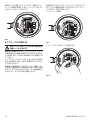
The installation is type CDS (Cable
Distribution System), do not connect it to
SELV circuits.
In order to reduce the risk of fire, only use
cable sizes greater than or equal to 26AWG.
Suggested coaxial cables are:
• RG59
• RG174A/U UL1354
Pass the coaxial cable(s) through the entry device.
Connect the coaxial cable through a 75 Ohm
BNC male connector (not supplied) to video BNC
connector(s) J6 (and J7).
Fig. 20
Fig. 21
MNVCMPXTJP_1415_EN
21
Telemetry and video signal transmission
pass through the Ethernet network cable.
Do not connect cable RS-485 and the video
cable.
FUS
E
J2
J3
J8
RL2
RL2
RL1
RL1
COM
AL5
AL4
AL3
AL2
AL1
Use a Category 5E or higher UTP network cable.
FUS1
Crimp the RJ45 connector on the Ethernet cable.
FUS2
VAR1
VIDEO - 1
J9
A
VIDEO - 2
B
GND
W
GND
VAR2
VAR3
J7
AC IN J1
L
FUS
Direct crimping is required if the product is
connected to a hub or switch. Cross crimping is
required if the product is connected directly to a PC.
J6
A
B
RS485
Operating mode valid only on version with
IP board.
Connect the crimped net cable to connector RJ45
located on the base of the unit.
N
E
EN - English - Instructions manual 6.1.7 Connection of the Ethernet cable
100nMBW3
Fig. 25
The example below shows a typical installation.
Fig. 22
Fig. 23
UTP cat 5E
Crimped cable.
1
2
3
4
1
2
3
4
A
B
Personal
Computer
5
6
7
8
5
6
7
8
5
6
7
8
Hub / Switch
UTP cat 5E
Straight-through cable.
1
2
3
4
A
Fig. 26
1
Fig. 24
22
2
3
4
B
5
6
7
8
Crossover cable.
MNVCMPXTJP_1415_EN
6.1.8 Telemetry line connections
• Plug the cabled connector to the J9 plug.
TELEMETRY LINE CONNECTIONS
Serial line
Terminal
Description
RS-485-1
A (+)
RS-485 line (1)
B (-)
RS-485 line (1)
SGND
RS-485-1 line
reference
A (+)
RS-485 line (2)
B (-)
RS-485 line (2)
SGND
RS-485-2 line
reference
In order to reduce the risk of fire, only use
cable sizes greater than or equal to 26AWG
(0.35mm²)
RS-485-2
The J9 connector supplies 2 RS-485 serial
communication lines (Tab. 2, page 23).
The lines can be configured in various ways according
to the dip-switch settings of the configuration board
(6.1.10 Unit address, communication protocol and
baud rate setting, page 25).
Telemetry lines connect the device to control and
programming units (keyboard or PC).
• Pass the telemetry cables through the entry device.
Instructions manual - English - EN
The installation is type TNV-1, do not
connect it to SELV circuits.
Tab. 2
The last 2 contacts (W and GND) of J9 connector are
referred to the external washer tank level monitoring
(if present).
• Take the J9 removable female connector from the
connectors board and connect the telemetry wires
to it.
J9
FUS
E
J3
J8
FUS2
RL2
RL2
RL1
RL1
COM
AL5
AL4
AL3
AL2
AL1
FUS1
VAR1
VIDEO - 1
J9
A
VIDEO - 2
B
GND
W
GND
L
N
E
VAR2
J7
AC IN J1
FUS
VAR3
J6
A
B
RS485
J2
100nMBW3
Fig. 27
MNVCMPXTJP_1415_EN
23
6.1.9 Alarm and relay connections
EN - English - Instructions manual The alarm contacts are present on J3 connector.
J3
6.1.9.1 Connecting an alarm with clean
contact (dry contact)
For a clean contact alarm (alarms AL1, AL2, AL3, AL4
and AL5), carry out the following connection:
A1
G
Dry contact
Fig. 28
The unit is provided with 5 clean contact alarms and
2 output relays with clean contact.
CONNECTING THE ALARMS AND RELAY
Terminal
Description
RL2
Relay 2 Terminal A
RL2
Relay 2 Terminal B
RL1
Relay 1 Terminal A
RL1
Relay 1 Terminal B
COM
A1-A2-A3-A4-A5 alarms
ground
AL5
Alarm 5 (clean contact)
AL4
Alarm 4 (clean contact)
AL3
Alarm 3 (clean contact)
AL2
Alarm 2 (clean contact)
AL1
Alarm 1 (clean contact)
Fig. 29
The clean contact alarm can be NO (normally open)
or NC (normally closed).
For further details on configuring and using the
alarms, refer to the related chapter (9.6.6.1 Alarms
Menu, page 49).
6.1.9.2 Relay connection
Relays can be used for low working
voltages only (up to 30Vac or 60Vdc) and
with a maximum current of 1A. Use cables
with a section suitable for the load to be
controlled. Use cables with a minimum
section of 0.25mm² (AWG 30) and maximum
section of 1.5mm² (AWG 16).
Tab. 3
Relays do not have polarity and therefore both
terminals of the same relay can be swapped for
alternating or continuous current voltages.
All alarms have an approximate reach of 200m, which
can be obtained using an unshielded cable with a
minimum section of 0.25mm² (AWG 30).
For further details on configuring and using the
relays, check the relative chapter (9.6.6.1 Alarms
Menu, page 49).
• Pass the alarms cables through the entry device.
• Pass the relays cables through the entry device.
• Take the J3 removable female connector from the
connectors board and connect the alarm wires to
it.
• Take the J3 removable female connector from the
connectors board and connect the relays wires to
it.
• Plug the cabled connector to J3 plug.
• Plug the cabled connector to J3 plug.
24
MNVCMPXTJP_1415_EN
6.1.10 Unit address, communication
protocol and baud rate setting
Take the configuration board from its J4 connector on
the connector board.
J4
FUS
E
FUS2
RL2
RL2
RL1
RL1
COM
AL5
AL4
AL3
AL2
AL1
FUS1
VAR1
VIDEO - 1
J9
J6
A
B
RS485
J2
J3
J8
A
VIDEO - 2
B
GND
W
GND
L
N
VAR2
E
VAR3
J7
AC IN J1
FUS
100nMBW3
Operating mode valid only on version with
IP board.
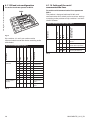
The unit can be configured in one way only. Set the
DIP exactly as shown in the table.
CONFIGURATION OF THE VERSION WITH IP BOARD
Address
1
Protocol
MACRO
Baudrate
38400
Serial line
One-way RS-485 line
Serial line terminations 1
ON
Serial line terminations 2
ON
Tab. 4
Once the dip-switches have been configured, close
the door and start configuring the IP parameters of
the pan & tilt.
6.1.12 Setting the configuration check
mode
Fig. 30
This board is used to set the communication
parameters of the serial lines RS-485-1 and RS-4852: the address of the receiver, the communication
protocol and baud rate.
7
DIP 2
8
4
6
0
0
4
DIP
6
8
U2
U3
U1
2 3 4
7 8 9
7 8 9
0
1
7 8 9
3
DIP
7
6
5
DIP
2 3 4
7 8 9
6
0
6
4
7 8 9
7 8 9
0
5
5
Fig. 31
4
3
1
3
2
2
0A 1
5
2 3 4
ON
2 3 4
5
1
6
U3
1
U2
U1
6
0
6
5
1
3
DIP
5
3
4
DIP
4
2 3 4
5
1
3
2
2
0A 1
SW 1=ON: Display Configuration. To be used only
to verify the configuration at the end of the setting.
During normal operation make sure the lever is on
OFF (SW 1=OFF).
1
5
DIP
ON
2 3 4
5
1
To set the operating mode operate on DIP 2.
Address and protocol board.
Fig. 32
MNVCMPXTJP_1415_EN
25
Instructions manual - English - EN
Before powering the device it must be correctly
configured by setting the dip switches on the circuit
board.
6.1.11 Configuration of the dip-switches
6.1.13 Baud rate configuration
To set the baud rate operate on DIP 2.
To set the serial communication lines operate on
DIP 2.
6
7
The product is designed with two RS485 serial
communication lines which can have various settings
according to the positions of dip-switches 5 and 6 on
the DIP selector.
8
U2
U3
U1
SERIAL COMMUNICATION LINES (DIP 2)
–
ON ON –
Two-way RS-485 TX/
RX line
–
OFF ON –
Line RS-485-1 reception,
line RS-485-2 repetition
–
ON OFF –
Two-way RS-422 line
–
OFF OFF –
One-way RS-485 line
SW 2
SW 3
–
ON
ON
ON
–
38400 baud
–
OFF ON
ON
–
19200 baud
–
ON
OFF ON
–
9600 baud
–
OFF OFF ON
–
4800 baud
–
ON
ON
OFF –
2400 baud
–
OFF ON
OFF –
1200 baud
–
ON
–
OFF OFF OFF –
300 baud
ON
–
–
–
–
Display enabled
OFF –
–
–
–
Display disabled
Configurations
display
SW 5-6-7-8
SW 1
Baud rate
selection
SW 4
Description
Configuration
SETTING THE BAUD RATE (DIP 2)
OFF OFF –
SW 7-8
SW 5
Serial line
SW 6
SW 1-2-3-4
7 8 9
Dip-switches 4, 3 and 2 are used to set the
communication rate of the device according to the
table below.
Description
7 8 9
Fig. 33
Configuration (see
related chapters)
5
0
2 3 4
6
7 8 9
0
6
0
6
5
4
5
1
3
DIP
4
3
2 3 4
1
4
DIP
3
2
2
0A 1
1
5
DIP
ON
2 3 4
5
EN - English - Instructions manual DIP 2
1
6.1.14 Setting of the serial
communication lines
Tab. 6
600 baud
Tab. 5
26
MNVCMPXTJP_1415_EN
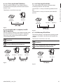
6.1.14.3 Two-way RS-422 line
With this type of setting it is possible to obtain a
bi-directional, half/duplex, communication on the
RS-485-1 line.
This setting allows full duplex communication
according to the RS-422 standard.
The RS-485-2 serial line is not used.
Instructions manual - English - EN
6.1.14.1 Two-way RS-485 TX/RX line
Line RS-485-1 is always in receiving mode (RS-422RX).
Line RS-485-2 is always in transmission mode (RS422-TX).
Control
keyboard
RS-485-1
Control
keyboard
TX/RX
RS-485-1
RS-485-2
Fig. 34
6.1.14.2 Line RS-485-1 reception, line RS485-2 repetition
With this type of setting it is possible to connect more
than one device in cascade. The signal is repeated
from every unit, making it possible to markedly
increase total distance.
It only works with mono-directional
protocols.
Fig. 36
6.1.14.4 One-way RS-485 line
The first line (RS485-1) will operate according to the
settings in the Address, Baudrate and Protocol dipswitch.
The RS-485-2 serial line is not used.
It only works with mono-directional
protocols.
This configuration does not allow the
remote updating of the firmware.
Control
keyboard
RS-485-1 RS-485-2
This configuration does not allow the
remote updating of the firmware.
RS-485-1
Control
keyboard
RS-485-1
Fig. 35
Fig. 37
MNVCMPXTJP_1415_EN
27
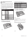
Dip-switches 7 and 8 terminate serial lines RS-485-1
and RS-485-2 respectively.
SW 1-2-3-4-5-6
SW 7
SW 8
–
ON
–
RS485-1 termination
enabled
–
OFF –
RS485-1 termination
disabled
2
0A 1
1
2 3 4
4
DIP
0
5
DIP
0
Configuration
7
ON
2 3 4
1
4
5
6
7
8
U2
U3
U1
2 3 4
0
3
DIP
3
Fig. 39
Address setting example:
Units number 431, dip-switch 3 = 4, dip-switch 4 = 3,
dip-switch 5 = 1.
Dip 3 set the cent, Dip 4 set the dec, Dip 5 set the
unit.
After you have set your parameters re-connect the
board on the J4 plug of the connection board.
8
U2
U3
U1
7 8 9
0
2 3 4
5
1
7 8 9
3
DIP
To set the address operate on DIP 3, 4 and 5.
6
7 8 9
0
6
0
6
5
DIP
6.1.17 Address configuration
4
4
DIP
4
Tab. 8
3
2 3 4
5
1
3
PELCO D
MACRO (VIDEOTEC)
2
5
2
0A 1
OFF
OFF
1
2 3 4
OFF
OFF
7 8 9
DIP 1
1
OFF
OFF
7 8 9
To set the protocol operate on DIP 1.
6
ON
OFF
RS-485-2 termination
enabled
6.1.16 Protocol configuration
5
ERNITEC
SENSORMATIC
1
Tab. 7
ON
OFF
OFF
4
OFF RS485-2 termination
disabled
ON
OFF
3
–
OFF
ON
2
–
OFF
OFF
1
ON
PANASONIC
5
–
Protocol
OFF
5
–
Serial line
terminations
SW 4
ON
5
Description
SERIAL LINE TERMINATIONS (DIP 2) AND
CONNECTIONS
SW 3
OFF
7 8 9
EN - English - Instructions manual Every peripheral that is situated at the end of a line
must be terminated using the appropriate dip-switch
in order to prevent signal reflection and distortion.
SW 2
ON
6
The board has two DIP switches used to configure the
serial line terminations (120 Ohm) (Tab. 7, page 28).
SETTING THE PROTOCOL (DIP 1)
SW 1
6
To set the serial line terminations operate on DIP
2.
Video positioning systems of the P&T can be
controlled by a range of protocols.
6
6.1.15 Serial line terminations and
connections
Fig. 38
Fig. 40
28
MNVCMPXTJP_1415_EN
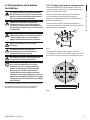
6.1.18 Earth wiring connection
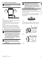
Verify that in the cap there isn’t dirt or debris.
Lubricate the threaded part of the lid, of the
connection compartment and the seal with technical
vaseline oil lubricant.
Arrange the cables so that there is no interference
when closing the threaded lid of the connection
compartment.
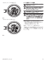
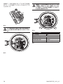
Fig. 41
The ring terminal for external bonding connection is
provided by the manufacturer.
The earthing conductor on the external of the unit
must have an actual cross section at least 4mm²
(AWG11).
Fig. 42
Screw by hand the threaded lid of the connection
compartment till the OR gasket reaches the tube.
This is for supplementary bonding connection
required by law. In any case, protective earthing
conductor must be applied to J1 inside connector (
6.1.5 Connection of the power supply line, page 19).
6.1.19 Connection compartment closing
If you can’t turn by hand the threaded
lid before the OR reaches the tube of the
connection compartment this means that
there are debris\dirt on the threads or that
the lid is misaligned: in this case there’s
a serious danger of threads damaging;
unscrew the lid and check the alignement
and/or clean the threads.
Never force the rotation of threaded lid
before the OR reaches the connection
compartment, otherwise thread damage
could occur.
MNVCMPXTJP_1415_EN
Fig. 43
Fig. 44
29
Instructions manual - English - EN
If you suspect that any kind of thread
damaging has occurred, suspend the
installation: the device could be no longer
safe for the installation on a potentially
explosive atmosphere: in this case contact
Videotec technical support.
The positioning unit must be connected to
an equipotential earth by the threaded M5
hole on the base.
EN - English - Instructions manual Use a 30mm wrench for tightly closing the threaded
lid of the connection compartment. Make sure that
there’s no gap between the threaded cap and the
junction box tube after tightening the cap.
7 Instructions for safe
operation
7.1 Safe operation
Before proceeding with the following
operations, make sure that the mains
voltage is correct.
7.1.1 Commissioning
Read the whole of this user’s handbook very carefully
before starting the installation.
Make connections and tests in the laboratory before
carrying out installation on site. Use appropriate tools
for the purpose.
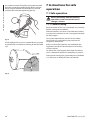
Fig. 45
Finally tighten the set screw supplied for this purpose
to prevent the unwanted unscrewing of the threaded
cap.
Test system operation for positive results before
closing the caps and allowing the presence of a
dangerous atmosphere.
Make sure that all the devices are certified for the
application and for the environment in which they
will be installed.
To reduce the risk of ignition don’t open the device
when a potentially explosive atmosphere is present.
After commissioning the system keep this handbook
in a safe place, available for later consultation.
Fig. 46
30
MNVCMPXTJP_1415_EN
7.1.2 Safety rules
Before starting any operation, make sure the power
supply is disconnected.
Before powering the system, install an overload
protection device in the electrical equipment for the
building.
Make sure that all precautions for personal safety
have been taken.
Installation of the electrical equipment must comply
with the local legislation in force.
The device must be installed only and exclusively by
qualified technical personnel.
7.1.3 Explosion prevention rules
Use appropriate tools for the area in which you are
working.
Always remember that the device must be connected
to an appropriate earth conductor.
Before doing any technical work or maintenance
on the device, make sure that potentially explosive
atmosphere is not present.
Before starting any operation, make sure the power
supply is disconnected.
Do not open any kind of cap if there is a possibility of
your being in a potentially explosive atmosphere.
Make all connections, installation and maintenance
work in a non-explosive atmosphere.
The only lid that the installer have to remove is those
of the connection compartment. Keep any other cap
tightly closed.
8 Switching on
The automatic pre-heating (De-Ice) process
could be started whenever the device is
switched on and the air temperature is
below 0°C. This process is used to ensure
that the device works properly even at
low temperatures. The duration ranges
between 60 and 120 minutes, depending
on conditions.
The unit is switched on by connecting the power
supply.
To switch off the unit disconnect the power.
8.1 Before powering the product
in an explosive atmosphere
Make sure that the unit and other
components of the installation are closed
so that it is impossible to come into contact
with live parts.
Make sure that the connection
compartment cap is properly and tightly
closed.
Make sure (if present) that the sealing of
the seal fitting is properly carried out and
that the sealing compound is completely
cured and hardened.
Make sure that the device has been
connected to an earth link as described.
Make sure that all parts are fastened down
firmly and safely.
MNVCMPXTJP_1415_EN
31
Instructions manual - English - EN
Given the considerable weight of the system, use an
appropriate transport and handling system.
EN - English - Instructions manual 9 Configuration
During the normal operation of the unit it is possible
to activate the On Screen Menu in order to set the
advanced functions using the corresponding keys.
For further information, refer to the manual of the
keyboard in use. For further information refer to the
relative chapter (10.12 Special controls, page 67).
9.1 Using the OSM
Exit the On Screen Menu with Zoom Wide (or Zoom-).
9.1.1 How to use the joystick
All operations in the menus are carried out using the
joystick.
Up
Left
Right
Each page of the OSM shows a list of parameters or
sub-menus that can be selected by the operator. To
scroll through the parameters move the cursor by
operating the joystick (up and down).
ADVANCED
-----------------------1 ZOOM SPEED
: 7
2>DIGITAL ZOOM
: N
3 WIDE DYNAMIC
: Y
4 HIGH RESOLUTION: N
5 BACKLIGHT COMP.: Y
6 FOCUS
>
7 EXPOSURE
>
8 INFRARED
>
9 WHITE BALANCE
>
Fig. 49
The symbol > at the end of a line indicates the
presence of a specific submenu. To enter the
submenu just confirm the menu item. To exit the
submenu use the Exit function (Zoom Wide).
Down
Fig. 47
Exit
9.2 How to move around the
menus
Confirm
ADVANCED
-----------------------1 ZOOM SPEED
: 7
2>DIGITAL ZOOM
: N
3 WIDE DYNAMIC
: Y
4 HIGH RESOLUTION: N
5 BACKLIGHT COMP.: Y
6 FOCUS
>
7 EXPOSURE
>
8 INFRARED
>
9 WHITE BALANCE
>
Fig. 50
Fig. 48
If using a control keyboard with a dual axis
joystick, use the Zoom Wide and Zoom
Tele keys to carry out the Exit and Confirm
commands.
32
MNVCMPXTJP_1415_EN
9.3 How to change the settings
ADVANCED
-----------------------1 ZOOM SPEED
: 7
2>DIGITAL ZOOM
: N
3 WIDE DYNAMIC
: Y
4 HIGH RESOLUTION: N
5 BACKLIGHT COMP.: Y
6 FOCUS
>
7 EXPOSURE
>
8 INFRARED
>
9 WHITE BALANCE
>
Fig. 51
After identifying the desired selection, confirm.
ADVANCED
-----------------------1 ZOOM SPEED
: 7
2>DIGITAL ZOOM
: N
3 WIDE DYNAMIC
: Y
4 HIGH RESOLUTION: N
5 BACKLIGHT COMP.: Y
6 FOCUS
>
7 EXPOSURE
>
8 INFRARED
>
9 WHITE BALANCE
>
Fig. 52
The parameter will stop flashing to confirm the
choice.
Move the cursor to the parameter to be changed and
confirm.
EDIT PRESET
-----------------------1 NR. :
1
2 ON
:
N
3>PAN :+ 0.00
4 TILT :+ 0.00
5 ZOOM :
0
6 FOCUS:
4096
7 SPEED: 100.0
8 PAUSE:
1
9 TEXT : Text 001
Fig. 53
The first digit in the numeric field to be changed will
flash and the last line of the display will show the
accepted limits for the field. Move in the field (left
and right) and change the sign or the numeric value
(up and down).
EDIT PRESET
-----------------------1 NR. :
1
2 ON
:
N
3>PAN :+000.00
4 TILT :+ 0.00
5 ZOOM :
0
6 FOCUS:
4096
7 SPEED: 100.0
8 PAUSE:
1
9 TEXT : Text 001
min:-180.00 max:+179.99
Fig. 54
After making the change, confirm. The cursor returns
to the left and the modified figure stops flashing.
The field will be forced to the minimum or maximum
allowed value if you try to insert a value outside the
limits.
MNVCMPXTJP_1415_EN
33
Instructions manual - English - EN
Move the cursor to the parameter to be changed and
confirm. The field will start flashing, indicating that
it is in change mode. Operating the joystick (up and
down) will show the alternative choices.
9.4 How to change the numeric
fields
EN - English - Instructions manual 9.5 How to change text
Move the cursor to the parameter to be changed and
confirm.
The Confirm command (Zoom Tele) inserts the
desired character.
EDIT TEXT: AREA
-----------------------Text: TEXT AREA1
↑
A B C D E F G
ERASE
H I J K L M N
SAVE
O P Q>R S T U
EXIT
V W X Y Z 0 1
abc
2 3 4 5 6 7 8
9 : ; . , ? !
‘ + - * / = “
< > SPACE ← →
EDIT ZONE
-----------------------1 NR
:
1
2 START:+ 0.00
3 STOP :+ 0.00
4>TEXT :TXT AREA1
Fig. 58
Fig. 55
The text editing display will open. The arrow symbol
will position itself under the character that can be
edited while the cursor > positions itself to the right
of the character to be entered.
EDIT TEXT: AREA
-----------------------Text: TEXT AREA1
↑
>A B C D E F G
ERASE
H I J K L M N
SAVE
O P Q R S T U
EXIT
V W X Y Z 0 1
abc
2 3 4 5 6 7 8
9 : ; . , ? !
‘ + - * / = “
< > SPACE ← →
Use:
• ERASE: To delete the whole text string.
• SAVE: To store the new text.
• EXIT: To exit the menu.
• abc: To display lower case letters.
EDIT TEXT: AREA
-----------------------Text: TEXT AREA1
↑
A B C D E F G
>ERASE
H I J K L M N
SAVE
O P Q R S T U
EXIT
V W X Y Z 0 1
abc
2 3 4 5 6 7 8
9 : ; . , ? !
‘ + - * / = “
< > SPACE ← →
Fig. 56
Fig. 59
You can move inside the menu using the joystick.
To exit the menu you can also use the Zoom Wide
key.
EDIT TEXT: AREA
-----------------------Text: TEXT AREA1
↑
A B C D E F G
ERASE
H I J K L M N
SAVE
O P Q>R S T U
EXIT
V W X Y Z 0 1
abc
2 3 4 5 6 7 8
9 : ; . , ? !
‘ + - * / = “
< > SPACE ← →
Fig. 57
34
MNVCMPXTJP_1415_EN
9.6 Configuration via OSM
1.
• Standard: Sets the standard operating mode
for the camera.
MAIN MENU
-----------------------1>LANGUAGE
>
2 CAMERA
>
3 MOTION
>
4 DISPLAY SETUP
>
5 OPTIONS
>
6 DEFAULT
>
7 INFO
>
Fig. 60
9.6.2 Language
LANGUAGE MENU
-----------------------1>ITALIANO
2 ENGLISH
OK
3 FRANCAIS
4 DEUTSCH
Configuration: Sets one of the default
configurations for the SONY module:
• Low Light: Sets the operating mode for dimly
lit environments.
• Far Mode: Sets the operating mode for large
areas. It enables the proportional zoom and
the digital zoom.
• Custom: Signals that the user has manually
selected the parameters of the camera.
2.
Area Titling: Allows access to the area titling
submenu.
3.
Masking: Allows access to the dynamic masking
submenu.
4.
Advanced: Allows access to the advanced
settings submenu of the SONY module.
CAMERA
-----------------------1>CONFIG.: STANDARD
2 ZONE TITLING
>
3 MASKING
>
4 ADVANCED
>
Fig. 61
Fig. 62
MNVCMPXTJP_1415_EN
35
Instructions manual - English - EN
9.6.1 Main menu
9.6.3 Camera menu
EN - English - Instructions manual 9.6.3.1 Zone Titling Menu
9.6.3.2 Zone Titling Menu (Edit Area)
This function allows setting up to eight (variable
dimension) areas with titling option.
Once inside the menu it is possibile to set the
following parameters:
Once inside the menu it is possibile to set the
following parameters:
1.
Number: Selects the area to be edited.
2.
Start: Sets the initial position of the area.
3.
Stop: Sets the final position of the area.
4.
Text: Modifies the text which is displayed when
moving within the zone.
1.
2.
Enabling: To enable onscreen display of the
message associated with the area currently
being shown.
Edit Area: Allows access to the zone parameter
setting submenu .
ZONE TITLING
-----------------------1>ENABLING: N
2 EDIT ZONE
>
EDIT ZONE
-----------------------1>NR. :
1
2 START:+ 0.00
3 STOP :+ 0.00
4 TEXT :TXT AREA1
Fig. 64
Fig. 63
Example: To enable titling of zone 1 when the device
is between +15° and +45°, it is necessary to:
• Enable area titling by setting Y as the value of
Enabling under the Area Titling menu.
• Set 1 as the value of parameter Nr under the Edit
Area menu.
• Set +15.00 as the value of parameter Start under
the Edit Zone menu.
• Set +45.00 as the value of parameter Stop under
the Edit Zone menu.
• If necessary, edit the displayed text by selecting
Text under the Edit Zone menu.
36
MNVCMPXTJP_1415_EN
To define zones proceed in a clockwise
direction as shown in the figure.
9.6.3.3 Masking Menu
Dynamic masking allows the creation of up to a
maximum of 24 masks so as to obtain the masking of
certain areas defined by the user.
Masks are defined in space and take account of the
horizontal, vertical and zoom depth position when
making the settings.
The unit automatically maintains the position and
dimension of the masking, based on the displayed
area.
Start1=15°
Stop2=135°
-90°
0°
-180°
Stop1=45°
90°
It is possible to simultaneously display up to 8 masks.
If the device is used at maximum speed, video signal
updating times become critical and it is necessary to
create masks larger than the object so that it remains
masked for longer during the passage and therefore
cannot be seen.
To ensure full functionality, the tilt position
of the masks must always be between -70
and +70 degrees; in addition , the size of
the mask must be double the size of the
object to be masked (both height-wise and
width-wise).
Start2=170°
Fig. 65
The default name and position of the
zones of the pan & tilt refer to the four
cardinal points. The NORTH position can
be modified by means of the Offset Pan
parameter in the movement menu (9.6.4
Movement Menu, page 44).
From the Masking menu it is possible to set the
following parameters:
1.
Mask Colour: Allows you to choose the colour
of the masks.
2.
Edit Masks: Allows access to the Edit Masks
submenu and set the dynamic masking
parameters.
MASKING
-----------------------1>COLOUR :
BLUE
2 EDIT MASKS
>
Fig. 66
MNVCMPXTJP_1415_EN
37
Instructions manual - English - EN
Setting the Start and Stop values of the Edit
Zone menu to zero will disable text display.
If there are overlapping areas, the area with
the highest number will prevail.
EN - English - Instructions manual 9.6.3.4 Masking Menu (Edit Masks)
9.6.3.5 How to create a new mask
Once inside the menu it is possibile to set the
following parameters:
Choose a disabled mask by selecting Mask Number
from the Edit Masks menu. Select Edit Mask to edit it (
Fig. 67, page 38).
1.
Mask Number: Allows you to choose the mask
on which to operate.
2.
Enable Mask: Enables or disables the selected
mask.
3.
Edit Mask: Allows the creation or editing of a
mask.
EDIT MASK
-----------------------1>MASK NUMBER
: 1
2 ENABLE MASK
: N
3 EDIT MASK
>
In the following example we shall mask a flower.
• Press the Iris Close button to pass from Masking
mode to Move Camera mode.
MASK 1
Edit Mask: ON
Iris Close→ PTZ enabled
Fig. 68
Fig. 67
Selecting the option Edit Mask in the menu makes it
possible to set new values for the selected mask.
• Operate the joystick on the keyboard to move the
unit and if necessary operate the zoom to centre
the flower on the screen.
MASK 1
PTZ Motions Enabled
Iris Open → Return
Fig. 69
38
MNVCMPXTJP_1415_EN
• When the desired result is obtained press the Iris
Open.
Fig. 70
• A small rectangle will appear. Operate the joystick
(Pan & Tilt) to enlarge the rectangle until it covers
the whole flower.
MASK 1
Edit Mask: ON
Iris Close→ PTZ enabled
Choose an enabled mask by selecting Mask Number
from the Edit Masks menu (Fig. 67, page 38). Select
Edit Mask to edit it.
• Operate the joystick (Pan & Tilt) to enlarge or
reduce the rectangle until the desired effect is
obtained.
MASK 1
Edit Mask: ON
Iris Close→ PTZ enabled
Fig. 72
• Confirm by turning the zoom to tele.
Fig. 71
• When the desired result is obtained confirm by
turning the zoom to tele.
MNVCMPXTJP_1415_EN
39
Instructions manual - English - EN
MASK 1
PTZ Motions Enabled
Iris Open → Return
9.6.3.6 How to modify a mask
EN - English - Instructions manual 9.6.3.7 Advanced Setting Menu
9.6.3.8 Advanced Setting Menu (Zoom)
This menu is used to configure the SONY module.
1.
Zoom Speed: Sets the speed of the zoom. The
speed ranges between 0 (minimum speed) and
7 (maximum speed).
2.
Digital Zoom: Enables the digital zoom.
1.
Zoom: Allows access to the Zoom submenu.
2.
Focus: Allows access to the Focus submenu.
3.
Exposure: Allows access to the Exposure.
4.
Infrared: Allows access to the Infrared submenu.
5.
White Balance: Allows access to the White
Balance submenu.
6.
Other: Allows access to the Other submenu.
ADVANCED
-----------------------1>ZOOM
>
2 FOCUS
>
3 EXPOSURE
>
4 INFRARED
>
5 WHITE BALANCE
>
6 OTHER
>
ZOOM
-----------------------1>ZOOM SPEED
:
7
2 DIGITAL ZOOM
:
N
Fig. 74
Fig. 73
40
MNVCMPXTJP_1415_EN
9.6.3.10 Advanced Setting Menu (Exposure)
Once inside the menu it is possibile to set the
following parameters:
Once inside the menu it is possibile to set the
following parameters:
1.
Focus Speed: Sets the speed of the Focus. The
speed ranges between 0 (minimum speed) and
7 (maximum speed).
2.
Autofocus: Enables or disables the autofocus.
When on, it is to automatically load Autofocus
at any positioning or movement of the zoom,
depending on the selected operating mode.
3.
Autofocus Type: Sets the type of Autofocus. The
possible values are:
• Normal: Autofocus is always enabled.
• Interval: The autofocus function is loaded at
regular intervals. The Interval is set every 5
seconds.
• Trigger: Autofocus is loaded at every PTZ
movement. This is the recommended
solution.
4.
Sensitivity: Sets the level of sensitivity. The
possible values are:
• Normal: Focusing at the highest possible
speed. This is the recommended solution.
• Low: Slowed-down focusing. It is useful in
case of dim lighting as it makes the image
more stable.
FOCUS
-----------------------1>FOCUS SPEED
:
2
2 AUTOFOCUS
:
N
3 AUTOFOCUS TYPE:TRIGGER
4 SENSITIVITY
: NORMAL
1-5. Mode: Sets the type of exposure control
Automatic, Manual, Shutter, Iris and Bright.
6.
Auto Slowshutter: If enabled, this function
automatically increases the exposure time to
improve night vision.
7-8. Compensation, Compensation Value: Sets the
exposure compensation.
9.
Backlight Compensation: Enables the
Backlight Compensation function. It improves
vision of any dark zone in the image.
In automatic mode it is possible to enable Backlight
compensation.
This is a dynamic self-configuration menu based on
the choice made and shows the parameters on which
it is possible to operate.
The chosen exposure operating mode is associated
to all presets.
The recommended setting is Automatic.
EXPOSURE
-----------------------1>MODE :
AUTOMATIC
6 AUTO SLOW SHUTTER : Y
7 COMPENSATION
: N
8 COMPENSATION VALUE: 7
9 BACKLIGHT COMP.
: N
Fig. 76
Fig. 75
MNVCMPXTJP_1415_EN
41
Instructions manual - English - EN
9.6.3.9 Advanced Setting Menu (Focus)
Gain
Exposure compensation
NTSC
PAL
0
1/1
1/1
Closed
-3db
-10,5db
1
1/2
1/2
F28
0db
-9db
2
1/4
1/3
F22
2db
-7,5db
3
1/8
1/6
F19
4db
-6db
4
1/15
1/12
F16
6db
-4,5db
5
1/30
1/25
F14
8db
-3db
6
1/60
1/50
F11
10db
-1,5db
7
1/90
1/75
F9.6
12db
0db
8
1/100
1/100
F5
14db
1,5db
9
1/125
1/120
F6.8
16db
3db
10
1/180
1/150
F5.6
18db
4.5db
11
1/250
1/215
F4.8
20db
6db
12
1/350
1/300
F4
22db
7,5db
13
1/500
1/425
F3.4
24db
9db
14
1/725
1/600
F2.8
26db
10,5db
15
1/1000
1/1000
F2.4
28db
16
1/1500
1/1250
F2
17
1/2000
1/1750
F1.6
18
1/3000
1/2500
19
1/4000
1/3500
20
1/6000
1/6000
21
1/10000
1/10000
Shutter
Iris
CORRESPONDING VALUES/EFFECTS ON THE SONY
MODULE LENS
Value
EN - English - Instructions manual The following table shows the inserted values with
the corresponding effects on the SONY module lens.
9.6.3.11 Advanced Setting Menu (Infrared)
Once inside the menu it is possibile to set the
following parameters:
1.
IR Mode: If set to OFF it forces the day mode in
a continuous manner (the switching on of the
illuminator, if present, is carried out by means
of the dusk swtich or by means of the control
on the keyboard). If set to ON it forces the night
mode in a continuous manner. If set to Auto, it
activates the automatic switching of the camera.
2.
Night Level: Sets the detection threshold of the
light conditions for the night mode switching.
Lower values correspond to lower lighting
levels.
3.
Night Delay: Sets the detection time of the
darkness conditions, expressed in seconds,
before switching to night mode.
4.
Day Level: Sets the detection threshold of the
light conditions for the day mode switching.
Lower values correspond to lower lighting
levels.
5.
Day Delay: Sets the detection time of the
light conditions, expressed in seconds, before
switching to night mode.
Tab. 9
42
MNVCMPXTJP_1415_EN
INFRARED
-----------------------1>IR MODE
:
AUTO
2 NIGHT LEVEL
:
5
3 NIGHT DELAY
:
5
4 DAY LEVEL
:
20
5 DAY DELAY
:
30
9.6.3.12 Advanced Setting Menu (White
Balance)
Once inside the menu it is possibile to set the
following parameters:
1.
Instructions manual - English - EN
To avoid false switching, we recommend
choosing the higher day switching
threshold and delay values.
Mode: Sets the type of control on White
Balance. The possible values are:
• Automatic: Sets automatic white balance.
This is the recommended solution.
• Manual: Enables manual setting of red and
blue gains.
• Outdoor: Sets fixed red and blue gains for
outdoor applications.
• Indoor: Sets fixed red and blue gains for
indoor applications.
• ATW: Enables Auto Tracing White Balance.
Fig. 77
2.
Red Value: Sets the value of the red gain.
This is a dynamic self-configuration menu based on
the choice made and shows the parameters on which
it is possible to operate.
3.
Blue Value: Sets the value of the blue gain.
The automatic Day/Night switching mode
of the module is strongly unadvisable
when swinging is subject to repeated
light variations during the night period,
for example during patrol, or due to the
switching on of auxiliary lighting devices.
Those situations can cause numerous
unwanted switching, compromising in this
way the functioning of the module.
WHITE BALANCE
-----------------------1>MODE
:
MANUAL
2 RED VALUE :
0
3 BLUE VALUE:
0
Fig. 78
This is a dynamic self-configuration menu based on
the choice made and shows the parameters on which
it is possible to operate.
MNVCMPXTJP_1415_EN
43
EN - English - Instructions manual 9.6.3.13 Advanced Setting Menu (Other)
1.
Sharpness: Sets the sharpness value of the
image.
2.
High Resolution: Enables the High Resolution
function. The output video signal has a higher
resolution.
3.
Wide Dynamic: Enables the Wide Dynamic
function. It improves vision when some zones
within the frame are much brighter than others.
4.
Stabilizer: Enables the electronic image
stabilization function.
5.
Progressive Scan: Enables the Progressive Scan
function. Gives a more stable image when the
Pan & Tilt is connected to a video server.
6.
Noise Reduction: Sets the noise reduction
level. Vary the parameter according to the
environmental conditions to obtain a higher
contrast image.
OTHER
-----------------------1 SHARPNESS
:
6
2 HIGH RESOLUTION :
N
3 WIDE DYNAMIC
: OFF
4 STABILIZER
:
N
5 PROGRESSIVE SCAN:
N
6 NOISE REDUCTION :
2
Fig. 79
9.6.4 Movement Menu
1.
Configuration: Sets one of the default
configurations of the pan & tilt.
• Wind Mode: Sets the movements speed
to adjust them to environments subject to
vibrations and/or windblasts.
• High Perf: Establishes that all the movements
are carried out at the maximum possible
speed.
• Custom: Signals that the user has manually
selected the movement speeds of the unit.
2.
Offset Pan: The pan & tilt has a mechanically
defined 0° position. The Offset Pan function
allows the definition of a different 0° position
using software.
3.
Manual Control: To access the submenus
operating the parameters associated with the
manual movements of the device.
4.
Preset: To access the submenus used to to edit
Preset values.
5.
Patrol: To access the submenus used to edit
Patrol values.
6.
Autopan: To access the submenus used to edit
Autopan values.
7.
Motions Recall: To access the submenu which
manages automatic load of the movements.
8.
Advanced: Allows access to the advanced
settings submenu.
MOTION
-----------------------1>CONFIG.
: STANDARD
2 OFFSET PAN:
+ 0.00
3 MANUAL CONTROL
>
4 PRESET
>
5 PATROL
>
6 AUTOPAN
>
7 MOTIONS RECALL
>
8 ADVANCED
>
• Standard: Sets the standard movement
speed.
• Low Speed: Sets the Low Speed mode that
slows down all pan & tilt operating speeds.
44
Fig. 80
MNVCMPXTJP_1415_EN
9.6.4.1 Manual Control Menu
9.6.4.2 Manual Control Menu (Limits)
Maximum Speed: Sets the maximum manual
speed.
Once inside the menu it is possibile to set the
following parameters:
2.
Fast Mode: Enables the Fast mode. When
enabled, this option is used to move fastly the
pan & tilt by moving the joystick to the limit
stop.
1.
Pan Limits: Enables the limits of Pan.
2.
Pan Start: Sets the start limit of Pan.
3.
Pan End: Sets the end limit of Pan.
4.
Tilt Limits: Enables the limits of Tilt.
5.
Tilt Start: Sets the start limit of Tilt.
6.
Tilt End: Sets the end limit of Tilt.
3.
Speed With Zoom: Enables the option Speed
with Zoom. When enabled, this parameter
automatically slows down the Pan & Tilt speed,
based on the Zoom factor.
4.
Tilt Factor: Sets the reduction factor of the tilt
axis manual speed.
5.
Autoflip: Enables the autoflip function (i.e.
when the tilt reaches the end of the stroke, it
automatically rotates the pan & tilt by 180°),
making it easier to follow the objects along
corridors or roads.
6.
Movement Limits: To access the Limits menu.
MANUAL CONTROL
-----------------------1>MAXIMUM SPEED
:100.0
2 FAST MODE
:
Y
3 VEL. WITH ZOOM :
N
4 TILT SCALE FACT.:
2
5 AUTOFLIP
:
Y
6 MOVEMENT LIMITS
>
Fig. 81
Instructions manual - English - EN
1.
LIMITS
-----------------------1>PAN LIMITS :
N
2 PAN START
: + 0.00
3 PAN END
: + 0.00
4 TILT LIMITD :
N
5 TILT START : + 0.00
6 TILT END
: + 0.00
Fig. 82
9.6.4.3 Preset Menu
1.
Edit Preset: Allows access to Edit Preset menu.
2.
Utility Preset: Allows access to Utilities
Configuration menu.
PRESET
-----------------------1>EDIT PRESET
>
2 PRESET UTILITIES
>
Fig. 83
MNVCMPXTJP_1415_EN
45
EN - English - Instructions manual 9.6.4.4 Preset Menu (Edit Preset)
9.6.4.5 Preset Menu (Utility Preset)
Once inside the menu it is possibile to set the
following parameters:
Once inside the menu it is possibile to set the
following parameters:
1.
Number: The Preset number to be edited.
2.
Enabling: Enabling preset.
3.
Pan: Pan position in degrees.
4.
Tilt: Tilt position in degrees.
5.
Zoom: Zoom position.
6.
Focus: Daytime and night-time position of the
focus.
7.
Speed: The speed at which the position is
reached when preset is recalled from the Patrol
and Scan function.
8.
Pause: Sets the dwell time in seconds before
starting the next movement in Patrol.
9.
Text: The text that is displayed when the preset
position is reached.
EDIT PRESET
-----------------------1>NR. :
1
2 ON
:
N
3 PAN :+ 0.00
4 TILT :+ 0.00
5 ZOOM :
0
6 FOCUS:
4096 - 5600
7 SPEED: 100.0
8 PAUSE:
1
9 TEXT : Text 001
Fig. 84
From the menu it is possible to directly store the
preset by sending the Iris Close command that
enables the pan & tilt movements.
1.
Daytime A.Focus: Enables the use of the
autofocus when loading the preset in daytime
mode. To guarantee fast and accurate focusing
of the image, disable the automatic focus.
2.
Night-time A.Focus: Enables the use of the
autofocus when loading the preset in night-time
mode. We advise enabling the automatic focus
when the pan & tilt is fitted with an infrared
illuminator, as the focal point varies depending
on whether the light is visible or infrared.
3.
Scan Speed: This is the reference speed used
when a preset position is recalled by the Scan
function.
4.
Default Speed: Changes the default speed
of the Presets. This value is used based on the
function Set Speed? to assign the same speed to
all Presets .
5.
Default Dwell Time: Changes the default pause
of the Presets. This value is used based on the
function Set Dwell Time? to assign all Presets the
same pause time.
6.
Set Speed: To assign all Presets the same default
speed.
7.
Set Dwell Time: To assign all Presets the same
default dwell time.
PRESET UTILITIES
-----------------------1>AUTOFOCUS DAY :
N
2 AUTOFOCUS NIGHT:
Y
3 SCAN SPEED
: 200.0
4 DEFAULT SPEED : 100.0
5 DEFAULT DWELL :
3
6 SET SPEED?
7 SET PAUSE?
Fig. 85
46
MNVCMPXTJP_1415_EN
9.6.4.6 Patrol Menu
First Preset: Sets the first preset of the Patrol
sequence.
2.
Last Preset: Sets the last preset of the Patrol
sequence.
3.
Random Mode: Enables random execution. The
sequence is re-calculated on a continuous basis.
PATROL
-----------------------1>FIRST PRESET :
1
2 LAST PRESET
: 250
3 RANDOM MODE
:
N
9.6.4.8 Motion Recall Menu
It is possibile to set the unit so that, after a given
inactivity interval, it automatically carries out the
movement function set by the operator.
From the menu it is possible to set the following
parameters:
1.
Movement Type: Choice of type of movement
to be loaded (None, Home, Autopan, Patrol, Tour
1, Tour 2, Tour 3).
2.
Movement Delay: The time (in seconds) that
needs to elapse from the state of inactivity of
the Joystick before loading the set movement.
MOTION RECALL
-----------------------1>MOVEMENT TYPE :
NONE
2 MOVEMENT DELAY:
60
Fig. 86
9.6.4.7 Autopan Menu
1.
Preset Outward Movement: Sets the initial
position of the Autopan.
2.
Preset Return Movement: Sets the final
position of the Autopan.
3.
Outward Movement Speed: Sets the speed of
the outward movement of the Autopan.
4.
Return Speed: Sets the speed of the return of
the Autopan.
Fig. 88
AUTO-PAN
-----------------------1>PRESET OUTWARD:
1
2 PRESET RETURN :
2
3 OUTWARD SPEED : 20.0
4 RETURN SPEED :100.0
Fig. 87
MNVCMPXTJP_1415_EN
47
Instructions manual - English - EN
1.
EN - English - Instructions manual 9.6.4.9 Advanced Menu
1.
Static Control: Enables control of the position
only when the pan & tilt is stopped
2.
Dynamic Control: Enables control of the
position only when the pan & tilt is moving
3.
Cyclic Homing: If other than zero, it sets a new
homing procedure after the specified number of
hours.
4.
Economy Mode: Reduces the motor toque
when the pan & tilt is not moving. Do not enable
in presence of strong wind or vibrations.
ADVANCED
-----------------------1>STATIC CONTROL
: Y
2 DYNAMIC CONTROL
: Y
3 CYCLIC HOMING
: 0
4 ECO MODE
: Y
Fig. 89
9.6.5 Display Menu
1.
PTZ Positions: If not on OFF, it is used to select
how the Pan, Tilt and Zoom positions are
displayed on the screen. It is possible to select
timed (1 S, 3 S and 5 S) or constant (CONST)
display.
2.
Preset Name: If not on OFF, it is used to select
how the text associated with the last-reached
Preset position is displayed on the screen. It
is possible to select timed (1 S, 3 S and 5 S) or
constant (CONST) display.
3.
Areas Name: If not on OFF, it is used to select
how the texts associated with active areas are
displayed. It is possible to select timed (1 S, 3 S
and 5 S) or constant (CONST) display.
4.
Pan & Tilt ID: If not on OFF, it shows the ID of
the pan & tilt.
5.
Received Commands: If not on OFF, it is used
to select how the received serial commands are
displayed. It is possible to select timed (1 S, 3 S
and 5 S) or constant (CONST) display.
6.
Horizontal Delta: This moves the menu texts
horizontally, for better centring.
7.
Vertical Delta: This moves the menu texts
vertically for better.
DISPLAY
-----------------------1>PTZ POSITIONS
: 1 S
2 PRESET NAME
: 3 S
3 AREAS NAME
: OFF
4 UNIT ID
:CONST
5 RECEIVED COMMAND:CONST
HORIZONTAL DELTA:
3
VERTICAL DELTA :
3
Fig. 90
48
MNVCMPXTJP_1415_EN
9.6.6 Options Menu
Ceiling Mount: When this mode is enabled the
image and the movements controls are turned
upsidedown.
2.
Alarms: Allows access to the Alarms menu.
3.
Washer: Allows access to the Washer menu.
OPTION
-----------------------1>CEILING MOUNT
:N
2 ALARMS
>
3 WASHER
>
Fig. 91
9.6.6.1 Alarms Menu
From these menus it is possible to set the following
values:
1.
Type: Set the type of contact: normally closed
(N.C.) or normally open (N.O.).
2.
Action: The type of action (Scan, Patrol,
Autopan, Tour 1, Tour 2 and Tour 3) carried out
by the unit when the alarm triggers. If Off is
selected, the alarm is disabled.
3.
Number: The preset to be reached when the
alarm’s type of action is Scan.
4.
Text: The message that is displayed when the
alarm is active.
Instructions manual - English - EN
1.
From the Alarms menu it is possible to access one of
the menus (Alarms 1-5) to edit the alarms parameters.
ALARM 1
-----------------------1>TYPE :N.C.
2 ACT. :SCAN
3 NR. : 1
4 TEXT :ALARM 1
1-5. Alarms 1-5: Allow access to the menus from
which it is possible to set the parameters of
Alarms 1 to 5.
6.
Alarms State: Allows access to the Alarms State
menu.
Fig. 93
ALARM
-----------------------1>ALARM 1
>
2 ALARM 2
>
3 ALARM 3
>
4 ALARM 4
>
5 ALARME 5
>
6 ALARMS STATE
>
Fig. 92
If the IR illuminator is fitted, alarm 5 is
reserved for the external dusk switch and
therefore alarm 5 will not be displayed on
the screen.
This is a dynamic self-configuration menu based on
the choice made and shows the parameters on which
it is possible to operate.
From the Alarms menu it is possible to access the
Alarms State menu where the state of alarms inputs
is displayed (CLOSED, contact closed, OPEN, contact
open).
ALARMS STATE
-----------------------ALARM 1
CLOSED
ALARM 2
OPEN
ALLARME 3
CLOSED
ALLARME 4
CLOSED
ALLARME 5
CLOSED
Fig. 94
MNVCMPXTJP_1415_EN
49
EN - English - Instructions manual 9.6.7 Washer Menu
9.6.8 Default Menu
The P&T offers the possibility to use a wiper and to
operate a pump to clean the glass.
1.
Delete Setup: Resets all the parameters except
the Presets.
To configure the Washer put the lens of the camera in
front of the nozzle of the Washer.
2.
Delete Preset: Deletes all previously stored
presets.
Save a preset (XY) that identifies this position; the
preset will be recalled by the pan & tilt when the
WASHER function is enabled.
From the menu, set the following parameters:
1.
Enable: Enables the Washer function.
2.
Nozzle preset: Enter the preset number (XY)
corresponding to the nozzle.
3.
Wiper On Delay: Sets the interval between the
enabling of the pump and that of the wiper.
4.
Washing length: Sets the length of the
brushing.
5.
Wiper Off Delay: Sets the length of the
brushing without water.
WASHER
-----------------------1>ENABLE
: N
2 NOZZLE PRESET
: 1
3 WIPER-ON DELAY
: 5
4 WASHING DURATION : 10
5 WIPER-OFF DELAY
: 5
Fig. 95
The enabling of the Washer function
reserves the use of Relay 2 to the switching
on of the pump and does not allow the
association of Relay 2 with an alarm.
DEFAULT
-----------------------1>DELETE SETUP?
2 DELETE PRESET?
Fig. 96
The above mentioned operations cause the
loss of all previously stored data (i.g. Preset,
Patrol, Autopan, Home…).
9.6.9 Info Menu
The menu is used to check the configuration of the
device and the installed firmware version.
INFO
-----------------------Address: 1
Protocol : MACRO
RS485-1:38400 N81 RX
RS485-2:38400 N81 REPEAT
FW: 0a (Apr 14 2009)
HW: 000-0000
Camera
: 36x
PC: MPX1PVW0000A
SN: 109032220029
Fig. 97
50
MNVCMPXTJP_1415_EN
9.6.10 Thermal Camera Menu
1.
Control: Sets the type of control on the thermal
camera.
Gain control: Allows access to the gain control
management submenu.
6.
• Indoor: The camera configuration is managed
by the pan & tilt.
ROI Setup: Allows access to the ROI
management submenu.
7.
• Outdoor: The camera configuration is
managed through the serial line RS-485-3
(only for models with double camera).
Thermal Analysis: Allows access to the thermal
analysis management submenu.
8.
Status: Allows access to the submenu
containing the technical features of the thermal
camera.
Configuration: To set one of the preset
configurations of the thermal camera.
• Standard: Sets the standard configuration of
the thermal camera.
• High Gain: Sets the configuration for a
higher-resolution image.
• Isotherm: Sets the configuration for
highlighting objects within a given
temperature range (9.6.10.8 Thermal Analysis
Menu (Isotherm), page 56).
• Custom: Signals that the operator has
manually chosen the configuration of the
thermal camera.
3.
Flat Field Correction: Allows access to the Flat
Field correction management submenu.
4.
Video Setup: Allows access to the video
configuration management submenu.
MNVCMPXTJP_1415_EN
THERMAL CAMERA
-----------------------1>CONTROL : INTERNAL
2 CONFIG. : STANDARD
3 FLAT FIELD CORRECTION>
4 VIDEO SETUP
>
5 GAIN CONTROL
>
6 ROI SETUP
>
7 THERMAL ANALYSIS
>
8 STATUS
>
Fig. 98
51
Instructions manual - English - EN
2.
5.
EN - English - Instructions manual 9.6.10.1 Flat Field Correction Menu
6.
The thermal camera is fitted with an internal
mechanism which periodically improves the quality
of the images called Flat Field Correction (FFC). The
parameters which manage this function are:
1.
• High: This setting aims to maximize the
contrast and is especially suitable for
applications which carry out the video
analysis of images.
Flat Field Auto: Enables the automatic
or manual Flat Field correction. When the
automatic correction is enabled, the camera
carries out a FFC after a given time or
temperature change. Vice versa, when the
manual correction is set, the FFC operations are
carried out when requested by the operator. We
advise setting the manual correction at all times.
2.
Interval: Sets the time that has to elapse before
carrying out a FFC when the dynamic gain range
is High. The time interval is indicated in frames
(33ms for NTSC and 40ms for PAL).
3.
Low Gain Interval: Sets the time that has to
elapse before carrying out a FFC when the
dynamic gain range is Low. The time interval is
indicated in frames (33ms for NTSC and 40ms for
PAL).
4.
Temperature:: Sets the temperature change
after which a FFC has to be carried out when the
dynamic gain range is High. The temperature
change is indicated in 0.1°C intervals.
5.
Low Gain Temperature: Sets the temperature
interval after which a FFC has to be carried
out when the dynamic gain range is Low.
The temperature change is indicated in 0.1°C
intervals.
Gain mode: Allows the setting of dynamic gain
range type:
• Low: This setting increases the dynamic range
of the image and diminishes the contrast. It is
especially suitable for identifying the hottest
elements in an image.
• Auto: This setting allows the camera to switch
between High and Low modes depending on
the type of image currently being displayed.
The parameters in the Gain Change Values
menu are used to change the behaviour of
this mode (9.6.10.2 Flat Field Correction Menu
(Gain Switch Values), page 53).
7.
Do FFC: Carries out a FFC.
8.
Gain Switch Values: Allows access to the Gain
Switch Values submenu.
FLAT FIELD CORRECTION
-----------------------1>FLAT FIELD AUTO:
Y
2 INTERVAL
: 7200
3 LOW GAIN INTER.: 1350
4 TEMPERATURE
:
5
5 LOW GAIN TEMP. :
10
6 GAIN MODE
: ALTO
7 DO FFC?
8 GAIN SWITCH VALUES
>
Fig. 99
We recommend that you do not change
the default values which have been set
to guarantee high quality images in any
operating condition.
52
MNVCMPXTJP_1415_EN
9.6.10.2 Flat Field Correction Menu (Gain
Switch Values)
1.
High-Low Threshold: Sets the temperature
threshold used by the High-Low Population
parameter to force the switching in Low Gain
mode. The value is indicated in degrees Celsius.
2.
High-Low Population: Sets the minimum pixel
percentage above which the switching in Low
Gain mode is carried out.
3.
Low-High Threshold: Sets the temperature
threshold used by the Low-High Population
parameter to force the switching in High Gain
mode. The value is indicated in degrees Celsius.
4.
Low-High Population: Sets the minimum pixel
percentage above which the switching in High
Gain mode is carried out.
GAIN SWITCH VALUES
-----------------------1>HIGH-LOW THRESH.: 140
2 HIGH-LOW POP.
:
20
3 LOW-HIGH THRESH.: 100
4 LOW-HIGH POP.
:
95
Once inside the Video Configuration menu it is
possible to set one of the following parameters:
1.
Lut Polarity: Sets the hue of the image shot by
the thermal camera.
2.
FFC Warning: Sets the interval for which a
coloured square is displayed on the upper right
side of the video when a FFC is about to be
carried out. The interval is indicated in frames
(33ms for NTSC and 40ms for PAL). A value lower
than 15 frames automatically disables the alert.
3.
Digital Zoom: Sets the type of zoom to be
applied to the video signal (OFF, Auto, 2x, 4x).
When using the Auto mode, the zoom of the
thermal camera automatically adjusts to that of
the SONY module.
4.
Dynamic DDE: Sets the value of the DDE filter,
used to improve the sharpness of outline.
Typical values range from 17 and 25. Value 17
disables the filter.
5.
Test Pattern: Enables the pattern test to check
the camera electronics.
VIDEO SETUP
-----------------------1>LUT POLARITY:WHITE HOT
2 FFC WARNING :
60
3 DIGITAL ZOOM:
AUTO
4 DYNAMIC DDE :
25
5 TEST PATTERN:
N
Fig. 100
We recommend that you do not change
the default values which have been set
to guarantee high quality images in any
operating condition.
Fig. 101
The settings of the Gain Change Values
Menu are effective only if the Gain
mode was set to Auto (9.6.10.1 Flat Field
Correction Menu, page 52).
MNVCMPXTJP_1415_EN
53
Instructions manual - English - EN
Once inside the Gain Switch Values menu it is
possible to set one of the following parameters:
9.6.10.3 Video Setup Menu
EN - English - Instructions manual 9.6.10.4 Gain Control Menu
2.
Once inside the Gain Control Configuration menu it is
possible to set one of the following parameters:
Plateau Value: Sets the maximum pixel value
which can be found in a grey scale.
3.
ITT Mean: Sets the mean point on a grey scale.
4.
Max Gain: Sets the maximum gain of the AGC.
5.
Contrast: Sets the contrast level of the image.
6.
Brightness: Sets the brightness level of the
image.
7.
Compensation: Sets the brightness
compensation level of the image.
1.
Algorithm: Sets the type of automatic gain
control (AGC) to optimize the image. It is
possible to choose between the following
algorithms:
• Automatic: Automatically sets the
contrast and brightness of the image
when environmental conditions change by
equalizing the grey scale histogram. The
image can be modified by changing the value
of the ITT Mean, Max Gain and Plateau Value
parameters. This is the default algorithm
and it is recommended for normal use of the
thermal camera.
• Once Bright: The set brightness level
represents the mean of the brightness values
of the image when this parameter is selected.
The image can be modified by changing the
value of the Contrast parameter.
• Auto Bright: The set brightness level
represents the mean of the brightness values.
Such level is updated in real-time. The image
can be modified by changing the values of
the Contrast and Compensation parameters.
• Manual: The contrast and brightness levels
are manually set by the user.
GAIN CONTROL
-----------------------1>ALGORITHM
:
AUTO
2 PLATEAU VAL.:
150
3 ITT MEAN
:
127
4 MAX GAIN
:
8
5 CONTRAST
:
32
6 BRIGHTNESS :
8192
7 BRIGHT. COMP:
+
0
Fig. 102
This is a dynamic self-configuration menu based on
the choice made and shows the parameters on which
it is possible to operate.
• Linear Histogram: Contrast and brightness
of the image are optimized using one linear
transfer function. The image can be modified
by changing the values of the ITT Mean and
Max Gain parameters.
54
MNVCMPXTJP_1415_EN
9.6.10.7 Thermal Analysis Menu (Spot Meter)
Once inside the ROI Configuration Menu it is
possible to change the region of interest (ROI) used
by the AGC algorithm to calculate the contrast and
brightness levels of the image.
Once inside the Point Measurement menu it is
possible to set one of the following parameters:
1.
Point 1 Left: Sets the left limit of the ROI.
2.
Point 1 Top: Sets the upper limit of the ROI.
3.
Point 2 Right: Sets the right limit of the ROI.
4.
Point 2 Bottom: Sets the lower limit of the ROI.
ROI SETUP
-----------------------1>POINT 1 LEFT : - 160
2 POINT 1 TOP
: - 128
3 POINT 2 RIGHT : + 160
4 POINT 2 BOTTOM: + 128
1.
Mode: Enables the visualization of the taken
temperature from the 4 pixels to the centre of
the image (in degrees Celsius or Fahrenheit). The
OFF option disables the visualization.
2.
Digital: Enables the visualization of the relative
symbol on the display.
3.
Thermometer: Enables the visualization of the
relative symbol on the display.
SPOT METER
-----------------------1>MODE
:
OFF
2 DIGITAL
:
N
3 THERMOMETER:
N
Fig. 103
9.6.10.6 Thermal Analysis Menu
1.
Spot Meter: Allows access to the point
measurement configuration submenu.
2.
Isotherm: Allows access to the isotherm
management submenu.
Fig. 105
THERMAL ANALYSIS
-----------------------1>SPOT METER
>
2 ISOTHERM
>
Fig. 104
MNVCMPXTJP_1415_EN
55
Instructions manual - English - EN
9.6.10.5 ROI Setup Menu
EN - English - Instructions manual 9.6.10.8 Thermal Analysis Menu (Isotherm)
9.6.10.9 Status Menu
Once inside the Isotherm menu it is possible to
enable a special colouring for objects included within
the set temperature interval. The parameters which
manage this function are:
Once inside the Status menu it is possible to learn the
technical features of the thermal camera.
1.
Enable: Enables the Isotherm function.
2.
Mode: Selects the way in which the interval is
indicated (in percentage or in degrees Celsius).
3.
Upper: Sets the upper limit of the Isotherm
function.
4.
Lower: Sets the lower limit of the Isotherm
function.
ISOTHERM
-----------------------1>ENABLE
:
N
2 MODE
:
PERCENT
3 UPPER
:
95
4 LOWER
:
90
STATUS
-----------------------VERSION SW : 0A00.022B
FW VERSION : 0802.0040
CAMERA S.N. :
00001234
SENSORE S.N.:
00001234
TEMPERATURE :
+0034.0
P.N. 41320035A-SPXXX
Fig. 107
Fig. 106
This is a dynamic self-configuration menu based on
the choice made and shows the parameters on which
it is possible to operate.
56
MNVCMPXTJP_1415_EN
9.7 Configuration of the version
with IP board
Choose one of the following configurations,
according to the number of channels to be
controlled.
CHANNELS
CPU
MEM
HDD
16
Intel Core 2
Duo 2.4 GHz
1GB
250GB
32
Intel Core 2
2GB
Duo 2.66 GHz
250GB
49
Intel Core 2
Quad 2.66
GHz
4GB
250GB
64
Intel Core 2
Quad 2.66
GHz
4GB
250GB
You will be asked login and password. When making
the settings for the first time insert the default login
and password.
Login: Admin (with a capital A)
Password: 123456
Fig. 108
Tab. 10
When installing for the first time, it will be necessary
to install OCX control in order to have a correct video
display and then confirm the settings in the following
pop-up menu.
9.7.2 Configuration procedure through
software
Once the pan & tilt has been preset and configured,
start configuring the IP parameters (6.1.7 Connection
of the Ethernet cable, page 22).
The IP address of the various units should be
configured using a PC.
Set the IP address of the PC: 192.168.0.1 (or
192.168.0.2, etc.).
To configure the unit, connect it physically to the
LAN, power it and run the browser Microsoft Internet
Explorer® version 6.0 or above.
To set the IP address of the various units,
power them, taking care to connect them
one at a time to the LAN (switch/hub).
Configure the unit and insert the settings
for at least the IP address and host name.
When the unit has all the desired settings,
connect the Ethernet cable and go on to
configure the next unit.
Fig. 109
When you have pressed OK/Enter in the pop-up
menu, the following window will appear.
Fig. 110
MNVCMPXTJP_1415_EN
57
Instructions manual - English - EN
9.7.1 Minimum system requirements
Enter address: 192.168.0.100.
EN - English - Instructions manual Continue by pressing the Install button. You carry out
this procedure once and only once for each PC that is
to have access to the device in the network.
9.7.2.1 WAN setting
Keep the account and the password in a
secure place.
The Live Video window will then appear.
Next, set the static IP address, which is used to
gain access to the unit that is to be configured. For
example, set a static IP and address 192.168.0.101.
Fig. 111
To make the parameter settings, click on the Quit
button next to the video display. The general
parameter setting menu will then appear.
Fig. 113
Next, click on Apply and then click on Save & Reboot.
Wait about 30 seconds, until the settings have been
saved. Re-connect to the modified address (e.g.
192.168.0.101), inserting the Account Name and
Password (use the default settings if they have not
been changed).
Fig. 112
58
MNVCMPXTJP_1415_EN
Then edit the other parameters, for example:
• Video Setting: To change resolution (720x576,
640x480, 352x288, 176x144) bit rate (setting
between 28kbit and 3 Mbit).
For telemetry, leave the default settings.
Before starting any operation, make sure
the power supply is disconnected.
In extreme cases, when you have forgotten
the password for accessing the unit via the
browser, you can also restore the factory
setting by connecting the reset switch
board situated inside the package and
pressing the Reset button.
For Reset to take effect, you have to disconnect the
power supply to the pan & tilt.
Remove the hexagon set screw and unscrew the
treaded cover of the junction box.
Fig. 114
After all the settings have been inserted, remember
to Save & Reboot, so that the changes will take effect.
02
01
• Factory Default: Used to restore default factory
settings.
Fig. 115
MNVCMPXTJP_1415_EN
59
Instructions manual - English - EN
Before doing any technical work or
maintenance on the device, make sure
that potentially explosive atmosphere is
not present. To reduce the risk of ignition
don’t open the device when a potentially
explosive atmosphere is present.
• Date Setting: To set date and time.
02
9.7.3 Installing the NVR software
A CD-ROM containing display and control software is
supplied for controlling the various units. Follow the
instructions below to install the software correctly.
Insert the CD-ROM in the player, and after a few
seconds the following introductory display will
appear.
FUS
E
J3
J8
FUS2
RL2
RL2
RL1
RL1
COM
AL5
AL4
AL3
AL2
AL1
FUS1
VAR1
VIDEO - 1
J9
A
VIDEO - 2
B
GND
W
GND
VAR2
J7
AC IN J1
L
FUS
VAR3
J6
A
B
RS485
J2
N
E
EN - English - Instructions manual Plug the cable (01), situated in the connection
compartment, in the reset switch board. Keep
pressed the reset button while reconnecting the
power supply.
100nMBW3
01
Fig. 116
Keep the button pressed for 5 seconds and then
release it. The factory default values of the unit are
restored.
Repeat the procedure with the cable of the thermal
camera(02), if present.
When finished change the O-ring gasket (new O-ring
is in the package), lubricate it and the threads with
technical vaseline oil.
Screw the threaded cover of the junction box and
fix the hexagon set screw proceeding in the reverse
order as shown in Fig. 115, page 59.
Fig. 117
Select Videotec NVR Professional and follow the
instructions that appear on the screen.
When you have completed installation, and the pan
& tilts have been configured as appropriate (see
previous section), you can run the NVR software to
make the initial settings for the system.
Start the Activemonitor software.
You will have to insert the usual User Name (default:
Admin) and Password (default: 123456)
60
MNVCMPXTJP_1415_EN
The first time you run the program, the following
display will appear, with an empty camera list
(Camera Tree).
Instructions manual - English - EN
Camera tree
When setting up manually, it is essential (as in
automatic setup, apart from the IP address) to set the
items marked by an asterisk, i.e.
Camera ID: Consecutively, 1, 2, 3 etc.
Tool bar
Camera IP: E.g. 192.168.0.102
Camera Model: Select 1-CH Video Server
Fig. 121
Set the name that will appear in the Camera Tree:
Camera Name: P&T 2 Example
Manual control
panel
Live Video
Fig. 118
At this point you need to add the various devices
present in the system. Click on the Setup button in
the control bar.
Setup button
Fig. 119
On completion, click on Apply and wait until the
settings have been saved.
Repeat the procedure for all the other devices
present in the system.
On completion of this stage, you should
close the NVR program and re-start it so
that the changes take effect. When the
program is restarted, the Camera Tree
should contain a list of the units in the
system for which settings have been made.
From the Media Source list, drag & drop the first unit
into one of the blue windows, and the live video
image should appear.
Then click on Setup Camera.
Fig. 120
Fig. 122 Example of drag & drop.
Insert the settings manually if you know the IP
addresses of the various units present, otherwise do
an automatic setup, which will identify the various
units.
Repeat the procedure for the other units.
MNVCMPXTJP_1415_EN
61
9.7.3.1 Controlling PTZ movements
EN - English - Instructions manual To set movement control via the control panel or via
mouse, proceed as follows:
Select the Setup / Setup Camera menu and select the
PTZ tab.
To control a unit via the control panel, select the unit
to be controlled by clicking with the mouse on the
corresponding video window, and then operate from
the control panel .
Select the first unit, or the one you want to configure,
from the Media Source list.
Check the Enable PTZ box.
Click on Apply.
This will automatically set the VIDEOTEC Macro
protocol at 38400 baud.
Repeat the procedure for the other units to be
controlled, directly from the PTZ setup menu ; just
select the other units present in the Media Source list
of the Camera Tree menu, one at a time, and check
Enable PTZ, then click on Apply.
Fig. 124
It is possible to set 5 different speeds for pan and tilt
and it is also possible to enable advanced functions
using the Action menu (which contains, for example,
the Autopan, Start, Stop commands etc.). If you want
to control the PTZ using the mouse, directly from
the video window, check Mouse PTZ in the control
panel. You can then use the mouse to control both
movements and zoom (Zoom + and Zoom - are
situated in the centre).
Fig. 123
When the unit settings have been inserted,
quit the NVR programm and re-start it so
that all the changes will be saved.
Mouse PTZ
Fig. 125
62
MNVCMPXTJP_1415_EN
To set the configuration parameters of the pan & tilt
by means of OSM, enable the corresponding function
using the control panel.
9.7.3.2 Preset and load positions
Enter the Setup / Setup Camera Menu and select the
PTZ Preset tab.
Select the desired unit from the Media Source list (e.g.
UNIT 3) and enable the Live View function.
OSD
Fig. 126
To move around within the menu use the up and
down arrow keys, and confirm using the Enter key.
The Leave key is used to quit the submenu/menu.
For a complete description of the
functions that can be set via OSM see 9.6
Configuration via OSM, page 35.
Fig. 127
Move to the desired position using Mouse control on
the video window.
Edit one of the boxes for the various preset positions
(Enter some text, such as Position No.2) and then
confirm by clicking on the blue button at the side.
Enter other preset positions as required.
On completion, click on Apply.
MNVCMPXTJP_1415_EN
63
Instructions manual - English - EN
Before making these settings, we
recommend enabling Mouse PTZ control,
so that it is easier to move around in the
position to be saved.
EN - English - Instructions manual Set the preset positions for the other units in the
same way.
Close the NVR application and re-start it to
save the settings.
When the application is re-started, the preset
positions can be loaded using the Go To command
on the control panel, and selecting the desired
position.
10 Instructions for safe
operation
10.1 Visualizing the state of the
pan & tilt
During normal operation the pan & tilt displays
on screen, at user's choice, the data organized as
illustrated. The visualization can be enabled or
disabled (9.6.5 Display Menu, page 48).
NORTH/EAST
ID: 1
12345
AL 1: Alarm 1
Pan : - 5.56
Tilt: +120.01
Zoom: 36.00x
Preset: Text 001
E7-PRESET NOT CONFIGURED
Fig. 129
Fig. 128
To control the other available functions, such as
recording on disc, playback and snapshot, and for
other detailed information about using the software,
see the manual on the installation CD: NVR User
Manual.
NORTH/EAST: Name of the area where one is
currently located.
ID: 1: Receiver’s address.
12345: Complete list of active alarms.
AL 1: Alarm 1: Text regarding the last active alarm.
Pan: - 5.56/Tilt: +120.01/Zoom: 36.00x: Current
position of Pan, Tilt and Zoom.
Preset: Text 001: Name of selected active preset.
E7-PRESET NOT CONFIGURED: The following field
shows the errors found while the system was running
or the commands received via serial (visualization can
be enabled or disabled only for received commands).
64
MNVCMPXTJP_1415_EN
10.2 Saving the current position
(Preset)
Using the control keyboard it is possible to save the
current position. For further information, refer to the
manual of the keyboard in use.
During the saving stage, it is possible to change the
speed at which Preset is reached using keys Focus
Far/Focus Near and to change the waiting time using
keys Iris Open/Iris Close.
-----------------------SET PRESET
Focus to change speed
Iris to change dwell
Joystick to exit
-----------------------Speed
: 100deg./s
Dwell
:
5s
Pan : - 5.56
Tilt: +120.01
Zoom:
36.00x
Fig. 130
10.2.2 Saving from the Menu
Refer to 9.6.4.3 Preset Menu, page 45.
10.3 Recalling a position (Scan)
Using the control device it is possible to recall a
previously saved Preset position (for additional
information refer to the manual of the device being
used).
10.4 Enabling the patrol (Patrol)
Using the control device it is possible to enable the
automatic patrol (for additional information refer to
the manual of the device being used). For further
information refer to the relative chapter (10.12
Special controls, page 67).
Disabling can be carried out by moving the joystick
or by recalling a different type of movement.
To configure the Patrol function refer to the related
chapter (9.6.4.6 Patrol Menu, page 47).
MNVCMPXTJP_1415_EN
Using the control device it is possible to enable the
Autopan. For further information, refer to the manual
of the keyboard in use. For further information refer
to the relative chapter (10.12 Special controls, page 67).
Disabling can be carried out by moving the joystick
or by recalling a different type of movement.
To configure the Autopan function, refer to 9.6.4.7
Autopan Menu, page 47.
10.6 Recalling a pattern (Tour)
The Tour functioning mode allows the repetition of a
previously recorded route in a continuous manner.
The pan & tilt can store up to 3 Tours, each lasting no
more than 2 minutes.
To save a Tour, enter the special preset of the number
of Tour to be saved using the keyboard (10.12 Special
controls, page 67).
To simplify the recording of the Tour, the pan &
tilt automatically limits the speed of the Pan & Tilt
depending on the Zoom factor.
While the Tour is being recorded, the remaining
recording time is displayed, as shown in the figure.
ID: 1
-----------------------RECORDING TOUR MODE
Iris to stop
99%
-----------------------Pan : - 5.56
Tilt: +120.01
Zoom:
36.00x
Fig. 131
To interrupt recording, press the Iris Open or Iris Close
key.
To start the play-back of a Tour, enter the special
preset of the number of Tour to be displayed using
the keyboard (10.12 Special controls, page 67).
65
Instructions manual - English - EN
10.2.1 Quick save
10.5 Enabling Autopan Function
EN - English - Instructions manual 10.7 Recalling the Home position
Using the control device it is possible to recall a
previously saved Home (Scan n.1) position (for further
information refer to the manual of the control device
in use).
10.8 Enabling the wiper (Wiper)
Do not use the wiper when the outside
temperature is below 0°C or in case of ice.
To enable/disable the wiper refer to the manual of
the control device in use or to the relative table (10.12
Special controls, page 67).
If it is left on, the Wiper automatically
disables itself.
66
10.9 Enabling the washer
Do not use the wiper when the outside
temperature is below 0°C or in case of ice.
To activate refer to the manual of the control device
used or the relevant chapter (10.12 Special controls,
page 67).
Refer to the relative chapter for the configuration (
9.6.7 Washer Menu, page 50).
10.10 Reboot the device
Using the control device it is possible to reboot the
unit. For further information refer to the manual of
the control device in use or to the relative table For
further information refer to the relative chapter (10.12
Special controls, page 67).
MNVCMPXTJP_1415_EN
10.11 Manual correction of a preset focusing
The manual correction of the Preset works only if the Daytime/Nigh-time Autofocus fields are
disabled (9.6.4.5 Preset Menu (Utility Preset), page 46).
10.12 Special controls
SPECIAL CONTROLS
Control
Protocol
MACRO
PELCO D
SENSORMATIC
ERNITEC
Tour 1 Start
recording
Save Preset 77
Save Preset 77
Save Preset 77
Save Preset 77
Save Pattern 2
Start recording
pattern 3
Tour 2 Start
recording
Save Preset 78
Save Preset 78
Save Preset 78
Tour 3 Start
recording
Save Preset 79
Tour 1 Start
Save Preset 80
Tour 2 Start
Save Preset 78
Save Preset 79
Save Preset 79
Save Preset 82
Save Preset 80
Save Preset 80
Pattern 2
Run pattern 3
Save Preset 81
Save Preset 81
Save Preset 81
Save Preset 82
Save Preset 82
Save Preset 82
Save Preset 80
Iris Open/Close
Wiper Start
Save Preset 80
Save Preset 51
Save Preset 81
Save Preset 52
Pattern 4
Tour Record
Stop
Save Preset 79
Save Preset 50
Pattern 3
Tour 3 Start
Save Preset 78
Save Preset 48
Save Pattern 4
Save Preset 81
Save Preset 77
Save Preset 47
Save Pattern 3
Save Preset 79
PANASONIC
Save Preset 82
Save Preset 53
IrisOpen/Close
Iris Open/Close
Ack
Save new pattern
Iris Open/Close
Iris Open/Close
Save Preset 85
Save Preset 85
Aux 3 ON
Aux 3 ON
Save Preset 85
Save Preset 85
Save Preset 85
Aux 3 ON
Aux 3 ON
Save Preset 54
Save Preset 86
Aux 3 OFF
Save Preset 86
Save Preset 86
Save Preset 86
Save Preset 86
Aux 3 OFF
Aux 3 OFF
Aux 3 OFF
Save Preset 55
Save Preset 87
Save Preset 87
Save Preset 87
Save Preset 87
Save Preset 87
Aux 4 ON
Aux 4 ON
Aux 4 ON
Aux 4 ON
Save Preset 56
Save Preset 88
Save Preset 88
Save Preset 88
Wip+
Wiper Stop
WipWasher
Was+
Night Mode
On
Save Preset 88
Night Mode
Off
Save Preset 89
Save Preset 88
Save Preset 57
MNVCMPXTJP_1415_EN
Save Preset 89
Save Preset 89
Save Preset 89
Save Preset 89
Save Preset 58
67
Instructions manual - English - EN
Load the preset whose focus needs to be changed using the Scan command. Change the focus using the
appropriate keys Focus Far/Focus Near without changing the Pan/Tilt/Zoom position. Save the preset using the
appropriate Preset command.
SPECIAL CONTROLS
EN - English - Instructions manual Control
Protocol
MACRO
PELCO D
Reboot the
device
Save Preset 94
Save Preset 94
Enabling
OSM
Save Preset 95
Patrol Start
Save Preset 93
Save Preset 93
Save Preset 93
Save Preset 93
Save Preset 93
Pat+
Pattern
Run pattern 1
Run patrol
Save Preset 60
Save Preset 92
Save Preset 92
Save Preset 92
Save Preset 92
Save Preset 92
Joystick
Joystick
Joystick
Joystick
Patrol Stop
SENSORMATIC
ERNITEC
Save Preset 94
Save Preset 94
Faster+ Zoom out+
Focus far+ Iris open
Ini+
Save Preset 95
Save Preset 95
Save Preset 94
Save Preset 61
Save Preset 95
Iris open+ Focus+
Zoom out
Men+
PANASONIC
Save Preset 95
Save Preset 46
Joystick
Save Preset 59
PatAutopan
Start
Save Preset 99
Save Preset 99
Save Preset 99
Save Preset 99
Save Preset 99
Apa+
Pattern 1
Run pattern 2
Run autopan
Save Preset 63
Autopan
Stop
Save Preset 96
Save Preset 96
Save Preset 96
Save Preset 96
Save Preset 96
Joystick
Joystick
Joystick
Joystick
Carry out a
FFC
Save Preset 74
Video
2 - thermal
camera
Save Preset 75
Video 2
integrated
module
Save Preset 76
Joystick
Save Preset 62
ApaSave Preset 74
Save Preset 74
Save Preset 74
Save Preset 74
Save Preset 43
Save Preset 75
Save Preset 75
Save Preset 75
Save Preset 75
Save Preset 44
Save Preset 76
Save Preset 76
Save Preset 76
Save Preset 76
Tab. 11
68
MNVCMPXTJP_1415_EN
Before doing any technical work or
maintenance on the device, make sure that
potentially explosive atmosphere is not
present.
11.2.1.2 Cleaning the germanium window
Remove the protective grid and spacer unscrewing
the 4 socket flat cap screws on the front of the
enclosure using 2mm no sparking hex wrench.
Instructions manual - English - EN
11 Maintaining and
cleaning
To reduce the risk of ignition, don’t open
the device when a potentially explosive
atmosphere is present.
Before doing any technical work on the
device, disconnect the power supply.
Repair of this equipment shall be carried
out by suitably trained or supervised by
VIDEOTEC personnel in accordance with
the applicable code of practice (e.g. IEC/EN
60079-19).
11.1 System configuration and
statistics display
When contacting Videotec for assistance please go
to the configuration and statistic page and send a
screenshot or serial number and device identification
code.
Fig. 132
Use neutral soap diluted with water. Take extra care
not to scratch or damage the outer surface treated
with carbon coating. Damage to this coating could
interfere with the transparency of the surface to
infrared light. Do not use ethyl alcohol, solvents,
hydrogenated hydrocarbons, strong acids or alkalis.
Using these products will irreparably damage the
germanium surface.
Once done cleaning, reassemble the spacer and the
protection grid.
11.2.1.3 Cleaning the device
11.2.1 Routine (to be carried out
regularly)
This should be done regularly. If a layer of dust
accumulates on the outside of the housing, it should
never be more than 5mm thick. The device should be
cleaned using a damp cloth; compressed air must not
be used. Maintenance frequency will depend on the
type of environment in which the housing is used.
11.2.1.1 Cleaning the glass
11.2.1.4 Inspecting the cables
Water should be used, or a liquid detergent that will
not generate a hazardous situation.
The cables should not show signs of damage or wear,
which could generate hazardous situations. In this
case extraordinary maintenance is necessary.
11.2 Maintenance and cleaning
by users
MNVCMPXTJP_1415_EN
69
11.2.2 Extraordinary (to be done only
under particular circumstances)
EN - English - Instructions manual Any other intervention that is not
comprised in the routine interventions
must be done in absence of potentially
explosive atmosphere.
For damage to any parts, repair or
replacement must be done by, or under
supervision of VIDEOTEC.
12 Disposal of waste
materials
This symbol mark and recycle system
are applied only to EU countries and not
applied to the countries in the other area of
the world.
Your product is designed and manufactured with
high quality materials and components which can be
recycled and reused.
Whenever replacing the parts as indicated,
always use VIDEOTEC original spare parts
and meticulously follow the maintenance
instructions supplied with every spare parts
kit.
This symbol means that electrical and electronic
equipment, at their end-of-life, should be disposed of
separately from your household waste.
The manufacturer declines all liability for
damage to any of the apparatus mentioned
in this handbook, when resulting from
tampering, use of non-original spare parts,
and from installation and maintenance/
repairs performed by non-authorised, nonskilled personnel.
In the European Union there are separate collection
systems for used electrical and electronic products.
Please dispose of this equipment at your local
Community waste collection or Recycling centre.
In all such circumstances, the product
should be sent to the workshop for the
necessary repairs or maintenance.
70
MNVCMPXTJP_1415_EN
13 Troubleshooting
PROBLEM
Ask for assistance from skilled personnel if:
• There is noticeable deterioration in performance
of the unit.
• The unit does not work properly, even though
all the instructions in this handbook have been
followed.
PROBLEM
The device is off and shows no
signs of life.
CAUSE
Wiring error, blown fuse.
SOLUTION
Make sure the connections are
correct; check the continuity of the
fuses and if one is blown replace it
using the size as indicated in the
table. If blown fuses are a frequent
problem, contact your authorised
service centre.
PROBLEM
The preset position settings do
not correspond to the shooting
area.
CAUSE
Loss of absolute position reference
point.
SOLUTION
Follow the procedure to calibrate
the P&T from the keyboard (see the
appropriate handbook), or reset the
apparatus by switching it off and on
again.
Address : 1
Protocol : MACRO
RS485-1:38400 N81 RX
RS485-2:38400 N81 REPEAT
232
: FW UPGRADE ONLY
FW: 0a (Jun 4 2009)
HW: 000-0001
DIP1.1: VIEW CONF. ON
CAUSE
Display Configuration dip-switch
rocker (DIP1, SW1).
SOLUTION
Switch off the pan & tilt, switch
down the dip-switch (DIP1, SW1).
Switch-on the unit again.
PROBLEM
During start-up the pan & tilt is
disabled and the following type
of message is shown:
Address : 1
DE-ICE PROCEDURE
IN PROGRESS…
REMAINING MINUTES:59
CAUSE
MNVCMPXTJP_1415_EN
The environment temperature is
too low.
71
Instructions manual - English - EN
• The unit is damaged after being dropped;
The monitor does not show
the picture taken but shows an
image of the type:
EN - English - Instructions manual SOLUTION
Wait until the end of the pre-heating
procedure. If the air temperature is
too low the unit will remain disabled
and the following message will be
shown:
Address : 1
DE-ICE PROCEDURE
-----------------------SYSTEM BLOCKED
TEMPERATURE TOO LOW
------------------------
PROBLEM
Error E3-PATROL WITHOUT
PRESET or error E4-PATROL, 1
PRESET ONLY.
CAUSE
The presets have not been
programmed.
SOLUTION
Program two or more presets and
then update the Patrol configuration
menu (10.2 Saving the current
position (Preset), page 65 and 9.6.4.6
Patrol Menu, page 47).
PROBLEM
Error E7-PRST. NOT
CONFIGURED.
CAUSE
Recalling of a non programmed
preset.
SOLUTION
Save the preset using the relative
control (10.2 Saving the current
position (Preset), page 65).
PROBLEM
Error E1-AUTOPAN WITHOUT
LIMITS.
CAUSE
The two presets used as limits have
not been programmed.
PROBLEM
Error E8-TOUR NOT
CONFIGURED.
SOLUTION
Program the two presets and then
update the Autopan configuration
menu (10.2 Saving the current
position (Preset), page 65 and 9.6.4.7
Autopan Menu, page 47).
CAUSE
Recalling of a non configured Tour.
SOLUTION
Save the Tour using the relative
control (10.6 Recalling a pattern
(Tour), page 65).
PROBLEM
Error E2-WIPER BLOCKED.
CAUSE
The wiper is either jammed or
broken.
SOLUTION
Check that the wiper is free to
move; if the problem persists, seek
assistance.
72
PROBLEM
Error E9-TEMP. TOO LOW.
CAUSE
The environment temperature is
too low.
SOLUTION
The movements of the P&T unit
is blocked to prevent mechanical
damage.
MNVCMPXTJP_1415_EN
14.1 MPX
If the device comes into contact with harsh
substances, it is the responsibility of the user to take
suitable precautions to prevent damage and not
compromise the type of protection.
14.1.1 General
AISI 316 stainless steel construction
Passivated and electropolished external surfaces
• Aggressive substances: Acidic liquids or gases
that may attack metals, or solvents that may affect
polymeric materials.
RTV silicone rubber
• Suitable precautions: Regular checks as part
of routine inspections or establishing from the
material’s data sheet that it is resistant to specific
chemicals.
Quick configuration and setup
It is the responsibility of the end users to make sure
that the materials used to build the product are
suitable for the intended installation site. If in doubt,
contact the manufacturer.
Instructions manual - English - EN
14 Technical data
NBR rotary seals
Silicone O-ring seals
Dynamic positioning control system
14.1.2 Mechanical
1 3/4" NPT hole for cable glands
Zero backlash
Horizontal rotation: 360° continous
Vertical rotation: -90° to +90°
Horizontal speed (variable): from 0.1° to 100°/s
Tilt speed (variable): from 0.1° to 100°/s
Preset accuracy: 0.02°
12mm thick tempered glass window
Integrated wiper
14.1.3 Electrical/Video
Input voltage:
• 24Vac, 50/60Hz, 120W max
1 video output 75 Ohm 1Vpp (PAL/NTSC)
Functions: Autopan, Preset, Patrol, Tour (maximum 3),
Autoflip
Maximum number of presets:
• VIDEOTEC MACRO Protocol: 250
• ERNITEC protocol: 250
• PANASONIC protocol: 250
• PELCO D Protocol: 99
• AMERICAN DYNAMICS protocol: 95
16-character string for zone and preset titling
I/O alarm card:
• 5 alarm inputs
• 2 relay outputs (1A 30Vac/60Vdc max)
MNVCMPXTJP_1415_EN
73
14.1.4 Communications
EN - English - Instructions manual Configuration through OSD
2 half-duplex serial RS-485 interfaces or full-duplex
RS-422
14.2 MPXT
14.2.1 General
AISI 316 stainless steel construction
Firmware updating from console in remote mode
(only VIDEOTEC MACRO and PELCO D protocols)
Passivated and electropolished external surfaces
Up to 999 units, addressable by means of dipswitches
NBR rotary seals
IP Streaming Module (optional)
Quick configuration and setup
RTV silicone rubber
Silicone O-ring seals
• MPEG4 compression
Dynamic positioning control system
• Compatible with ONVIF 1.01
14.2.2 Mechanical
• Compatible with VMS Milestone XProtect suite
• LAN 10/100 Mbit/s RJ45 interface
• Resolutions: Full D1 (720x576) @30fps, VGA
(640x480), CIF (352x288), QCIF (176x144)
14.1.5 Protocols
AMERICAN DYNAMICS, ERNITEC, PANASONIC, PELCO
D, VIDEOTEC MACRO*
The product may be interfaced with devices not manufactured by
VIDEOTEC. It is possible that the interface protocols have changed or
are in a different configuration from earlier tested units by VIDEOTEC.
VIDEOTEC recommends a test prior to installation. VIDEOTEC will
not be liable for any installation costs or lost revenues in the event a
compatibility problem will occur.
*AMERICAN DYNAMICS, ERNITEC, PANASONIC, PELCO are registered
trademarks.
14.1.6 Environment
1 3/4" NPT hole for cable glands
Zero backlash
Horizontal rotation: 360° continous
Vertical rotation: -90° to +90°
Variable pan speed: from 0.1° to 100°/s
Variable tilt speed: from 0.1° to 100°/s
Preset accuracy: 0.02°
12mm thick tempered glass window
8mm thick germanium window
Integrated wiper
14.2.3 Electrical/Video
Input voltage:
• 24Vac, 50/60Hz, 120W max
Indoor / Outdoor
2 video outputs 75 Ohm 1Vpp (PAL/NTSC)
Operating temperature: -40°C / +60°C (-40°F / +140°F)
Functions: Autopan, Preset, Patrol, Tour (maximum 3),
Autoflip
Installation temperature (not operative): -40°C /
+60°C (-40°F / +140°F)
Maximum number of presets:
Surge immunity: up to 2KV line to line, up to 4KV line
to earth (Class 4)
• VIDEOTEC MACRO Protocol: 250
14.1.7 Brackets and adapters
• PANASONIC protocol: 250
MPXWBA
AISI 316L stainless steel wall
bracket
• PELCO D Protocol: 99
MPXCW
AISI 316L stainless steel corner
adapter module
MPXCOL
AISI 316L stainless steel pole
adapter module
MPXWBTA
AISI 316L stainless steel
parapet or ceiling mounting
bracket
• ERNITEC protocol: 250
• AMERICAN DYNAMICS protocol: 95
16-character string for zone and preset titling
I/O alarm card:
• 5 alarm inputs
• 2 relay outputs (1A 30Vac/60Vdc max)
14.1.8 Package
Unit weight:
MPX
74
27kg (60lb)
MNVCMPXTJP_1415_EN
14.2.4 Communications
Configuration through OSD
Firmware updating from console in remote mode
(only VIDEOTEC MACRO and PELCO D protocols)
Up to 999 units, addressable by means of dipswitches
ELECTRICAL RATING
Power
supply
Normal usage to be
specified on product
label
Short term de-icing
cicle. Peak maintaining
a minimum internal
temp at 5°C
24Vac
1.08A, 50/60Hz, 25.9W
5A, 50/60Hz, 120W
Tab. 12
IP Streaming Module (optional)
• MPEG4 compression
• Compatible with ONVIF 1.01
• Compatible with VMS Milestone XProtect suite
• LAN 10/100 Mbit/s RJ45 interface
• Resolutions: Full D1 (720x576) @30fps, VGA
(640x480), CIF (352x288), QCIF (176x144)
14.2.5 Protocols
AMERICAN DYNAMICS, ERNITEC, PANASONIC, PELCO
D, VIDEOTEC MACRO*
The product may be interfaced with devices not manufactured by
VIDEOTEC. It is possible that the interface protocols have changed or
are in a different configuration from earlier tested units by VIDEOTEC.
VIDEOTEC recommends a test prior to installation. VIDEOTEC will
not be liable for any installation costs or lost revenues in the event a
compatibility problem will occur.
*AMERICAN DYNAMICS, ERNITEC, PANASONIC, PELCO are registered
trademarks.
14.2.6 Environment
Indoor / Outdoor
Operating temperature: -40°C / +60°C (-40°F / +140°F)
Installation temperature (not operative): -40°C /
+60°C (-40°F / +140°F)
Surge immunity: up to 2KV line to line, up to 4KV line
to earth (Class 4)
14.2.7 Brackets and adapters
MPXWBA
AISI 316L stainless steel wall
bracket
MPXCW
AISI 316L stainless steel corner
adapter module
MPXCOL
AISI 316L stainless steel pole
adapter module
MPXWBTA
AISI 316L stainless steel
parapet or ceiling mounting
bracket
14.2.8 Package
Unit weight:
MPXT
31kg (68lb)
MNVCMPXTJP_1415_EN
75
Instructions manual - English - EN
2 half-duplex serial RS-485 interfaces or full-duplex
RS-422
14.3 Electrical rating
14.4 Camera
EN - English - Instructions manual ANALOGUE CAMERAS AVAILABLE
SONY Day/Night 36x
SONY Day/Night 28x High
sensitivity
PAL
PAL
NTSC
NTSC
Optical zoom
36x
28x
Wide Dynamic Range (Fix/Auto)
p
–
True progressive SCAN
p
–
Digital image stabilisation
p
p
White balance
Auto, ATW, Indoor, Outdoor (Fix/
Auto), Sodium Vapor Lamp (Fix/
Auto)
Auto, ATW, Indoor, Outdoor (Fix/
Auto), Sodium Vapor Lamp (Fix/
Auto)
High horizontal resolution
Up to 550 TV Lines
Up to 550 TV Lines
Day/Night (Auto ICR)
p
p
Image Sensor
1/4" EXView HAD CCD
1/4" Super HAD CCD II
Number of effective Pixels
~ 440 000 pixel
~ 380 000 pixel
~ 440 000 pixel
Min. night Illumination (ICR ON) (typical)
0.01 Lux / 1/3s
0.01 Lux / 1/4s
0.0015 Lux / 1/3s 0.0015 Lux / 1/4s
Min. day Illumination (ICR OFF) (typical)
0.1 Lux / 1/3s
0.1 Lux / 1/4s
0.16 Lux / 1/3s
“Shutter Time” automatic increase to improve the night
surveillance
p
p
S/N ratio
Greater than 50dB
Greater than 50dB
AE control
Automatic, Shutter priority,
Diaphragm priority, Brightness
priority and Manual
Automatic, Shutter priority,
Diaphragm priority, Brightness
priority and Manual
Back light compensation
On/Off
On/Off
~ 380 000 pixel
0.16 Lux / 1/4s
Spherical masking (3D) of Privacy zones with automatic p
upgrade
p
Privacy Zone Masking
On/Off (24 positions)
On/Off (24 positions)
Maximum number of masking blocks to be displayed
8
8
Resolution of masking blocks
160x120 HxV
160x120 HxV
Masking
Up to 15 different masking types: 14 Up to 15 different masking types: 14
colour types or mosaic
colour types or mosaic
Focusing system
Auto (Sensitivity: Normal, Low),
Trigger PTZ, Manual
Auto (Sensitivity: Normal, Low),
Trigger PTZ, Manual
“Smart” lens control
SONY Modular Automatic Lens
Reset Technology
SONY Modular Automatic Lens
Reset Technology
High Zoom and Wide Horizontal Field of View Capability
p
p
Optical zoom
36x, f=3.4 (wide) to 122.4mm (tele)
/ F1.6 to F4.5
28x, f=3.5 (wide) to 98mm (tele) /
F1.35 to F3.7
Digital Zoom
12x (432x with optical zoom)
12x (336x with optical zoom)
Angle of view (A)
57.8 degrees (wide) to 1.7 degrees
(tele)
55.8 degrees (wide) to 2.1 degrees
(tele)
Minimum object distance
320mm (12.6in) (wide) to 1500mm
(59.1in) (tele)
10mm (0.4in) (wide) to 1500mm
(59.1in) (tele)
Electronic Iris Speed
1/1 ÷ 1/10 000s
1/1 ÷ 1/10 000s
Tab. 13
76
MNVCMPXTJP_1415_EN
MNVCMPXTJP_1415_EN
THERMAL CAMERAS AVAILABLE (RESOLUTION 160X120)
Lens 19mm
PAL
Lens 13mm
NTSC
PAL
Lens 9mm
NTSC
PAL
NTSC
Image sensor
Uncooled VOx microbolometer
Uncooled VOx microbolometer
Uncooled VOx microbolometer
Resolution
160x120
160x120
160x120
Pixel dimensions
25μm
25μm
25μm
Spectral response - long wave infrared (LWIR)
from 7.5μm to 13.5μm
from 7.5μm to 13.5μm
from 7.5μm to 13.5μm
Internal shutter (only for sensor compensation)
Video stop < 1sec.
Video stop < 1sec.
Video stop < 1sec.
Digital Detail Enhancement (DDE)
p
p
p
Digital Zoom
2x, 4x
2x, 4x
Image updating frequency
8.3fps
7.5fps
8.3fps
7.5fps
8.3fps
7.5fps
Image updating high frequency
25fps
30fps
25fps
30fps
25fps
30fps
Scene temperature range
-40°C ÷ +160°C (-40°F ÷ +320°F)
-40°C ÷ +160°C (-40°F ÷ +320°F)
-40°C ÷ +160°C (-40°F ÷ +320°F)
Horizontal field of view
12°
17°
25°
Vertical field of view
10°
14°
20°
F-number
F/1.25
F/1.25
F/1.25
Thermal sensitivity (NEdT)
< 50mK a f/1.0
< 50mK a f/1.0
< 50mK a f/1.0
Person (detection / recognition / identification)
450m / 112m / 56m (1476ft / 367ft /
184ft)
300m / 74m / 37m (984ft / 243ft / 121ft)
205m / 52m / 26m (673ft / 171ft / 85ft)
Auto (detection / recognition / identification)
1280m / 330m / 165m (4199ft / 1083ft
/ 541ft)
840m / 215m / 108m
590m / 150m / 74m
160x120
160x120
160x120
2x, 4x
Tab. 14
77
Instructions manual - English - EN
EN - English - Instructions manual 78
THERMAL CAMERAS AVAILABLE (RESOLUTION 320X256)
Lens 35mm
PAL
Lens 25mm
NTSC
PAL
Lens 19mm
NTSC
PAL
Lens 13mm
NTSC
PAL
Lens 9mm
NTSC
PAL
NTSC
Image sensor
Uncooled VOx microbolometer
Uncooled VOx microbolometer
Uncooled VOx microbolometer
Uncooled VOx microbolometer
Uncooled VOx microbolometer
Resolution
320x256
320x256
320x256
320x256
320x256
Pixel dimensions
25μm
25μm
25μm
25μm
25μm
Spectral response - long wave infrared
(LWIR)
from 7.5μm to 13.5μm
from 7.5μm to 13.5μm
from 7.5μm to 13.5μm
from 7.5μm to 13.5μm
from 7.5μm to 13.5μm
Internal shutter (only for sensor compensation)
Video stop < 1sec.
Video stop < 1sec.
Video stop < 1sec.
Video stop < 1sec.
Video stop < 1sec.
Digital Detail Enhancement (DDE)
p
p
p
p
p
Digital Zoom
2x, 4x
2x, 4x
2x, 4x
2x, 4x
Image updating frequency
8.3fps
7.5fps
8.3fps
7.5fps
8.3fps
7.5fps
8.3fps
7.5fps
8.3fps
7.5fps
Image updating high frequency
25fps
30fps
25fps
30fps
25fps
30fps
25fps
30fps
25fps
30fps
Scene temperature range
-40°C ÷ +160°C (-40°F ÷
+320°F)
-40°C ÷ +160°C (-40°F ÷
+320°F)
-40°C ÷ +160°C (-40°F ÷
+320°F)
-40°C ÷ +160°C (-40°F ÷
+320°F)
-40°C ÷ +160°C (-40°F ÷
+320°F)
Horizontal field of view
13°
18°
24°
34°
48°
Vertical field of view
10°
14°
18°
26°
37°
F-number
F/1.2
F/1.1
F/1.25
F/1.25
F/1.25
Thermal sensitivity (NEdT)
< 50mK a f/1.0
< 50mK a f/1.0
< 50mK a f/1.0
< 50mK a f/1.0
< 50mK a f/1.0
Person (detection / recognition / identification)
800m / 200m / 105m
590m / 148m / 75m
450m / 112m / 56m (1476ft
/ 367ft / 184ft)
300m / 74m / 37m (984ft /
243ft / 121ft)
205m / 52m / 26m (673ft /
171ft / 85ft)
Auto (detection / recognition / identification)
2250m / 590m / 290m
(7382ft / 1936ft / 951ft)
1650m / 430m / 215m
(5413ft / 1411ft / 705ft)
1280m / 330m / 165m
(4199ft / 1083ft / 541ft)
840m / 215m / 108m
590m / 150m / 74m
Tab. 15
320x240
320x240
320x240
320x240
320x240
2x, 4x
MNVCMPXTJP_1415_EN
MNVCMPXTJP_1415_EN
THERMAL CAMERAS AVAILABLE (RESOLUTION 336X256)
Lens 35mm
PAL
Image sensor
Lens 25mm
NTSC
Uncooled VOx microbolometer
336x240
PAL
Lens 19mm
NTSC
Uncooled VOx microbolometer
336x256
336x240
PAL
Lens 13mm
NTSC
Uncooled VOx microbolometer
336x256
336x240
PAL
Lens 9mm
NTSC
Uncooled VOx microbolometer
336x256
336x240
PAL
NTSC
Uncooled VOx microbolometer
Resolution
336x256
Pixel dimensions
17μm
17μm
17μm
17μm
17μm
336x256
336x240
Spectral response - long wave infrared (LWIR)
from 7.5μm to 13.5μm
from 7.5μm to 13.5μm
from 7.5μm to 13.5μm
from 7.5μm to 13.5μm
from 7.5μm to 13.5μm
Internal shutter (only for sensor compensation)
Video stop < 1sec.
Video stop < 1sec.
Video stop < 1sec.
Video stop < 1sec.
Video stop < 1sec.
Digital Detail Enhancement (DDE)
p
p
p
p
p
Digital Zoom
2x, 4x
2x, 4x
2x, 4x
2x, 4x
Image updating frequency
8.3fps
7.5fps
8.3fps
7.5fps
8.3fps
7.5fps
8.3fps
7.5fps
8.3fps
7.5fps
Image updating high frequency
25fps
30fps
25fps
30fps
25fps
30fps
25fps
30fps
25fps
30fps
Scene temperature range
-40°C ÷ +160°C (-40°F ÷
+320°F)
-40°C ÷ +160°C (-40°F ÷
+320°F)
-40°C ÷ +160°C (-40°F ÷
+320°F)
-40°C ÷ +160°C (-40°F
÷ +320°F)
-40°C ÷ +160°C (-40°F
÷ +320°F)
Horizontal field of view
9,3°
13°
17°
25°
35°
Vertical field of view
7,1°
10°
13°
19°
27°
F-number
F/1.2
F/1.1
F/1.25
F/1.25
F/1.25
Thermal sensitivity (NEdT)
< 50mK a f/1.0
< 50mK a f/1.0
< 50mK a f/1.0
< 50mK a f/1.0
< 50mK a f/1.0
Person (detection / recognition / identification)
1140m / 280m / 142m (3740ft
/ 919ft / 466ft)
820m / 210m / 104m
570m / 144m / 72m
390m / 95m / 47m
(1280ft / 312ft / 154ft)
250m / 63m / 31m
(820ft / 207ft / 102ft)
Auto (detection / recognition / identification)
3000m / 800m / 200m (9843ft
/ 2625ft / 656ft)
2200m / 580m / 290m (7218ft
/ 1903ft / 951ft)
1550m / 400m / 200m (5085ft
/ 1312ft / 656ft)
1080m / 275m / 140m
(3543ft / 902ft / 459ft)
720m / 175m / 88m
2x, 4x
Tab. 16
79
Instructions manual - English - EN
EN - English - Instructions manual 80
THERMAL CAMERAS AVAILABLE (RESOLUTION 640X512)
Lens 35mm
PAL
Lens 25mm
NTSC
PAL
Lens 19mm
NTSC
PAL
Lens 13mm
NTSC
PAL
Lens 9mm
NTSC
PAL
NTSC
Image sensor
Uncooled VOx microbolometer
Uncooled VOx microbolometer
Uncooled VOx microbolometer
Uncooled VOx microbolometer
Uncooled VOx microbolometer
Resolution
640x512
640x512
640x512
640x512
640x512
Pixel dimensions
17μm
17μm
17μm
17μm
17μm
Spectral response - long wave infrared
(LWIR)
from 7.5μm to 13.5μm
from 7.5μm to 13.5μm
from 7.5μm to 13.5μm
from 7.5μm to 13.5μm
from 7.5μm to 13.5μm
Internal shutter (only for sensor compensation)
Video stop < 1sec.
Video stop < 1sec.
Video stop < 1sec.
Video stop < 1sec.
Video stop < 1sec.
Digital Detail Enhancement (DDE)
p
p
p
p
p
Digital Zoom
2x, 4x
2x, 4x
2x, 4x
2x, 4x
Image updating frequency
8.3fps
7.5fps
8.3fps
7.5fps
8.3fps
7.5fps
8.3fps
7.5fps
8.3fps
7.5fps
Image updating high frequency
25fps
30fps
25fps
30fps
25fps
30fps
25fps
30fps
25fps
30fps
Scene temperature range
-40°C ÷ +160°C (-40°F ÷
+320°F)
-40°C ÷ +160°C (-40°F ÷
+320°F)
-40°C ÷ +160°C (-40°F ÷
+320°F)
-40°C ÷ +160°C (-40°F ÷
+320°F)
-40°C ÷ +160°C (-40°F ÷
+320°F)
Horizontal field of view
18°
25°
32°
45°
69°
Vertical field of view
14°
20°
26°
37°
56°
F-number
F/1.2
F/1.1
F/1.25
F/1.25
F/1.4
Thermal sensitivity (NEdT)
< 50mK a f/1.0
< 50mK a f/1.0
< 50mK a f/1.0
< 50mK a f/1.0
< 50mK a f/1.0
Person (detection / recognition / identification)
1140m / 280m / 142m
(3740ft / 919ft / 466ft)
820m / 210m / 104m
570m / 144m / 72m
390m / 95m / 47m (1280ft /
312ft / 154ft)
250m / 63m / 31m (820ft /
207ft / 102ft)
Auto (detection / recognition / identification)
3000m / 800m / 200m
(9843ft / 2625ft / 656ft)
2200m / 580m / 290m
(7218ft / 1903ft / 951ft)
1550m / 400m / 200m
(5085ft / 1312ft / 656ft)
1080m / 275m / 140m
(3543ft / 902ft / 459ft)
720m / 175m /88m
Tab. 17
640x480
640x480
640x480
640x480
640x480
2x, 4x
MNVCMPXTJP_1415_EN
15 Technical drawings
Instructions manual - English - EN
The dimensions of the drawings are in millimetres.
Ø 138
N°4 M10
232
398
336
Fig. 133 MAXIMUS MPX.
MNVCMPXTJP_1415_EN
81
Ø 138
N°4 M10
232
398
453
Fig. 134 MAXIMUS MPXT.
Headquarters Italy Videotec S.p.A.
France Videotec France S.à.r.l.
Asia Pacific Videotec (HK) Ltd
Americas Videotec Security, Inc.
Via Friuli, 6 - I-36015 - Schio (VI) Italy
Tel. +39 0445 697411 - Fax +39 0445 697414
Email: [email protected]
Flat 8, 19/F. - On Dak Industrial Building
2-6 Wah Sing Street - Kwai Chung, NT, Hong Kong
Tel. +852 2333 0601 - Fax +852 2311 0026
Email: [email protected]
Voie du Futur, Zac des Portes - 27100 - Val-de-Reuil, France
Tel. +33 2 32094900 - Fax +33 2 32094901
Email: [email protected]
35 Gateway Drive, Suite 100 - Plattsburgh, NY 12901 - U.S.A.
Tel. +1 518 825 0020 - Fax +1 518 825 0022
Email: [email protected] - www.videotec.us
www.videotec.com
MNVCMPXTJP_1415_EN
MAXIMUS MPX,
MAXIMUS MPXT
ステンレス製防爆カメラポジショニングユニット
「IPモデルは、TIIS国内耐圧防爆認定未取得品です。」
JA 日本語 - 取扱説明書
目次
日本語
1 本取扱説明書についての情報..................................................................................... 7
1.1 記号の意味........................................................................................................................................................ 7
2 著作権および商標についての注記.............................................................................. 7
3 安全規定..................................................................................................................... 7
4 製品の特徴................................................................................................................. 9
4.1 製品の内容と用途........................................................................................................................................... 9
4.1.1 サーマルカメラ付きバージョン.............................................................................................................................. 10
5 製品を使用前の準備................................................................................................. 11
5.1 使用前の安全のための注意......................................................................................................................11
5.2 梱包の開封と内容物....................................................................................................................................12
5.2.1 梱包の開封.................................................................................................................................................................... 12
5.2.2 内容物............................................................................................................................................................................. 12
5.3 梱包資材の安全な処分...............................................................................................................................12
5.4 設置前の準備作業........................................................................................................................................13
5.4.1 パラペットマウントまたはシーリングマウント................................................................................................... 13
5.4.2 ブラケットを使った固定............................................................................................................................................ 14
5.4.3 ポールマウントアダプターまたはコーナーマウントアダプターを使った固定........................................ 14
5.4.3.1 ポールマウントアダプターを使った固定.................................................................................................................................14
5.4.3.2 コーナーマウントアダプターを使った固定.............................................................................................................................15
5.4.4 ルーフの固定................................................................................................................................................................ 15
6 組み立てと設置......................................................................................................... 16
6.1 設置....................................................................................................................................................................16
6.1.1 使用分野......................................................................................................................................................................... 16
6.1.2 設置方法......................................................................................................................................................................... 16
6.1.3 ベースへのケーブル結線.......................................................................................................................................... 17
6.1.4 ケーブルの挿入口....................................................................................................................................................... 18
6.1.5 電源ラインの結線....................................................................................................................................................... 19
6.1.6 1つ以上の映像ケーブルの接続............................................................................................................................ 21
6.1.7 イーサーネットのケーブル接続.............................................................................................................................. 22
6.1.8 テレメトリーラインの接続........................................................................................................................................ 23
6.1.9 アラームとリレーの接続............................................................................................................................................ 24
6.1.9.1 クリーンコンタクト
(ドライコンタクト)のアラーム接続.......................................................................................................24
6.1.9.2 リレーの接続.....................................................................................................................................................................................24
6.1.10 ユニットのアドレス、通信プロトコル、伝達速度の設定................................................................................ 25
6.1.11 DIP スイッチの定義.................................................................................................................................................. 25
6.1.12 設定確認モードの設定............................................................................................................................................ 25
6.1.13 ボーレートの設定..................................................................................................................................................... 26
6.1.14 シリアル通信ラインの設定.................................................................................................................................... 26
6.1.14.1 RS-485 TX/RX 双方向ライン......................................................................................................................................................27
6.1.14.2 受信のRS-485-1 ラインr、
リピートのRS-485-2 ライン......................................................................................................27
6.1.14.3 RS-422 双方向ライン...................................................................................................................................................................27
6.1.14.4 RS-485 片方向ライン....................................................................................................................................................................27
6.1.15 シリアルライン終端部設定と接続....................................................................................................................... 28
6.1.16 プロトコルの設定...................................................................................................................................................... 28
MNVCMPXTJP_1415_JP
3
6.1.17 アドレスの設定.......................................................................................................................................................... 28
6.1.18 接地............................................................................................................................................................................... 29
6.1.19 接続ボックスを閉める............................................................................................................................................. 29
7 安全な状況で作動させるための注意........................................................................ 30
7.1 安全な状況での作動....................................................................................................................................30
7.1.1 試運転............................................................................................................................................................................. 30
7.1.2 安全のための指示...................................................................................................................................................... 31
7.1.3 爆発防止のための指示............................................................................................................................................. 31
8 電源を入れる............................................................................................................ 31
8.1 爆発性雰囲気で製品に電源を入れる前に...........................................................................................31
9 システム設定............................................................................................................. 32
9.1 OSM の使用....................................................................................................................................................32
9.1.1 ジョイスティックの操作............................................................................................................................................. 32
9.2 メニュー間の移動..........................................................................................................................................32
9.3 設定の変更......................................................................................................................................................33
9.4 設定数値の変更.............................................................................................................................................33
9.5 テキストの変更...............................................................................................................................................34
9.6 OSM を通じた設定.......................................................................................................................................35
9.6.1 メインメニュー............................................................................................................................................................. 35
9.6.2 言語.................................................................................................................................................................................. 35
9.6.3 カメラメニュー............................................................................................................................................................. 35
9.6.3.1 エリアタイトル設定メニュー........................................................................................................................................................36
9.6.3.2 エリアタイトル設定メニュー (エリアの編集)..........................................................................................................................36
9.6.3.3 マスキングメニュー.........................................................................................................................................................................37
9.6.3.4 マスキングメニュー (マスクの編集)..........................................................................................................................................38
9.6.3.5 新規マスクの作成............................................................................................................................................................................38
9.6.3.6 マスクの編集.....................................................................................................................................................................................39
9.6.3.7 高度な設定メニュー........................................................................................................................................................................40
9.6.3.8 高度な設定メニュー (Zoom).......................................................................................................................................................40
9.6.3.9 高度な設定メニュー (Focus)........................................................................................................................................................41
9.6.3.10 高度な設定メニュー (露光)........................................................................................................................................................41
9.6.3.11 高度な設定メニュー (赤外線ライト).......................................................................................................................................42
9.6.3.12 高度な設定メニュー (ホワイトバランス)...............................................................................................................................43
9.6.3.13 高度な設定メニュー (その他)....................................................................................................................................................44
9.6.4 動作メニュー................................................................................................................................................................. 44
9.6.4.1 マニュアルコントロールメニュー...............................................................................................................................................45
9.6.4.2 マニュアルコントロールメニュー (リミット)............................................................................................................................45
9.6.4.3 プリセットメニュー..........................................................................................................................................................................45
9.6.4.4 プリセットメニュー (プリセットの編集).....................................................................................................................................46
9.6.4.5 プリセットメニュー (プリセットユーティリティ)......................................................................................................................46
9.6.4.6 パトロールメニュー.........................................................................................................................................................................47
9.6.4.7 オートパンメニュー.........................................................................................................................................................................47
9.6.4.8 モーション呼び出しメニュー........................................................................................................................................................47
9.6.4.9 高度な設定メニュー........................................................................................................................................................................48
9.6.5 表示メニュー................................................................................................................................................................. 48
9.6.6 オプションメニュー..................................................................................................................................................... 49
9.6.6.1 アラームメニュー.............................................................................................................................................................................49
9.6.7 ウォッシャー設定メニュー........................................................................................................................................ 50
9.6.8 初期化設定メニュー................................................................................................................................................... 50
9.6.9 情報メニュー................................................................................................................................................................. 50
4
MNVCMPXTJP_1415_JP
9.6.10 サーマルカメラのメニュー.................................................................................................................................... 51
9.6.10.1 フラットフィールド訂正メニュー..............................................................................................................................................52
9.6.10.2 フラットフィールド訂正メニュー (ゲイン変更値)................................................................................................................53
9.6.10.3 映像設定メニュー..........................................................................................................................................................................53
9.6.10.4 ゲイン制御メニュー......................................................................................................................................................................54
9.6.10.5 ROIの設定のメニュー..................................................................................................................................................................55
9.6.10.6 温度分析メニュー..........................................................................................................................................................................55
9.6.10.7 温度分析メニュー (測定点)........................................................................................................................................................55
9.6.10.8 温度分析メニュー (アイソサーム)............................................................................................................................................56
9.6.10.9 ステータスメニュー......................................................................................................................................................................56
9.7 IP ボードの設定.............................................................................................................................................57
9.7.1 コンピュータの最小システム条件.......................................................................................................................... 57
9.7.2 システム設定の手順................................................................................................................................................... 57
9.7.2.1 WAN設定............................................................................................................................................................................................58
9.7.3 NVR ソフトウェアのインストール........................................................................................................................... 60
9.7.3.1 PTZ動作の制御.................................................................................................................................................................................62
9.7.3.2 プリセットと位置の呼び出し........................................................................................................................................................63
10 安全な状況で作動させるための注意...................................................................... 64
10.1 パン/チルト旋回装置の状態の表示.....................................................................................................64
10.2 現在位置の保存(プリセット登録)........................................................................................................65
10.2.1 クイック保存................................................................................................................................................................ 65
10.2.2 メニューからの保存................................................................................................................................................. 65
10.3 位置の呼び出し
(スキャン).....................................................................................................................65
10.4 パトロール機能をオンにする.................................................................................................................65
10.5 オートパン機能をオンにする..................................................................................................................65
10.6 ツアーの呼び出し.......................................................................................................................................65
10.7 ホームポジションの呼び出し..................................................................................................................66
10.8 ワイパーをオンにする (Wiper)...............................................................................................................66
10.9 ウォッシャーをオンにする........................................................................................................................66
10.10 機器のリブート..........................................................................................................................................66
10.11 プリセットの焦点調整の手動訂正......................................................................................................67
10.12 特別のコマンド.........................................................................................................................................67
11 メンテナンスとクリーニング..................................................................................... 69
11.1 システム設定と統計データの表示........................................................................................................69
11.2 ユーザーによるメンテナンスとクリーニング.....................................................................................69
11.2.1 通常のメンテナンス(定期的に実施)................................................................................................................. 69
11.2.1.1 ガラスの掃除..................................................................................................................................................................................69
11.2.1.2 ゲルマニウム窓ガラスのクリーニン........................................................................................................................................69
11.2.1.3 機器のクリーニング......................................................................................................................................................................69
11.2.1.4 ケーブルの点検..............................................................................................................................................................................69
11.2.2 特別メンテナンス(特殊な状況でのみ実施)................................................................................................... 70
12 廃棄物の処理......................................................................................................... 70
13 Troubleshooting................................................................................................... 71
14 製品仕様................................................................................................................. 73
14.1 MPX.................................................................................................................................................................73
14.1.1 全体............................................................................................................................................................................... 73
14.1.2 機械部........................................................................................................................................................................... 73
MNVCMPXTJP_1415_JP
5
14.1.3 電気/映像.................................................................................................................................................................... 73
14.1.4 通信............................................................................................................................................................................... 74
14.1.5 プロトコル................................................................................................................................................................... 74
14.1.6 環境............................................................................................................................................................................... 74
14.1.7 ブラケットとアダプター........................................................................................................................................... 74
14.1.8 梱包............................................................................................................................................................................... 74
14.2 MPXT...............................................................................................................................................................74
14.2.1 全体............................................................................................................................................................................... 74
14.2.2 機械部........................................................................................................................................................................... 74
14.2.3 電気/映像.................................................................................................................................................................... 74
14.2.4 通信............................................................................................................................................................................... 75
14.2.5 プロトコル................................................................................................................................................................... 75
14.2.6 環境............................................................................................................................................................................... 75
14.2.7 ブラケットとアダプター........................................................................................................................................... 75
14.2.8 梱包............................................................................................................................................................................... 75
14.3 消費電力........................................................................................................................................................75
14.4 カメラ..............................................................................................................................................................76
15 製品外形寸法図...................................................................................................... 81
6
MNVCMPXTJP_1415_JP
1 本取扱説明書についての情
報
3 安全規定
製造者は、本取扱説明書に記載のない不適正
な使用による損傷について、全ての責任を免
除させていただきます。
ま た、内容を予告なし
に変更する場合があります。本取扱説明書に
記載している内容には万全を期していますが、
製造者はお客様が本取扱説明書の情報を用
いて行った一切の行為について、いかなる責
任も負いません。同様のことは、本取扱説明書
の制作に携わった人や会社についても言える
ものとします。
本ユニットの設置・使用の前には、本取扱説明書を
よく読むようにしてください。本取扱説明書はいつで
も参照できる場所に保管してください。
1.1 記号の意味
危険!
爆発の危険。
爆発の危険を防止するために注意してお読み
ください。
機器は、
アース導線に接続される必要がありま
す
(保護用アース)。このような接続は、内部コ
ネクターのみを通じて実施される必要がありま
す。J1 (6.1.5 電源ラインの結線, ページ 19).
等電位ボンディングは、地元の法規定により、
追加のアース線接続が義務付けられている場
合にのみ、実施してください。
危険!
危険度 高。
感電の危険。異なる指示がある場合を除き、
何らかの作業をする前には必ず製品の電源を
切るようにしてください。
警告!
危険度 中。
この作業は装置を適正に作動させるために非
常に重要なものです。手順の指示をよく読み、
決められた方法にしたがって手順を実行して
ください。
INFO
装置の特徴についての説明。
続くステップを理解するために注意して読むこ
とを推奨します。
2 著作権および商標について
の注記
引用された製品名または会社名は、各会社に属する
商標または登録済みの商標です。
MNVCMPXTJP_1415_JP
図1
法規定により、等電位ボンディングが義務付け
られている場合にしようする外部の穴。保護用
アース線端子として使用してはいけません。
7
• 説明書を参照してください。
• 説明書を保管してください。
• 全ての注意を守ってください。
• 全ての指示にしたがってください。
• 本機器は遠隔制御されますので、何時でも位置が
変更される可能性があります。本機器は、可動部
が他の物体と衝突して危険な状況を生じさせな
いようにするなど、可動部との接触による事故を
防止するように設置してください。
• 爆発性雰囲気との接続による発火の危険を低減
させるために、本機器を開ける前に本機器を電源
配線から外すようにしてください。製品は封をし
た状態で使用してください。
• 本機器が頑丈に固定されていることを確認して
ください。
• 機器は、-40°
C~60°
C (-40°
F~140°
F) の温度環
境での使用条件で関係機関から承認を受けてい
ます。
• 接続ボックスの蓋は、機器の配線をするためにだ
けに外されるものとします。他の栓・蓋は製造者
以外の人が外すことは禁止されています。
• 本機器の設置は、IEC/EN 60079-14 の規則に適合
する専門技術員が行う必要があります。
• 直射日光にさらされると本機器の表面温度が上が
ります。本機器の表面温度クラスは、直射日光に
さらされた場合を考慮せずに、周辺環境の温度の
みにて計算されています。
• 電気設備には、必要時に見分けや使用が可能な
断路器を設置する必要があります。
• 磨耗・劣化したコード、
ワイヤー、ケーブルを使用
しないでください。
• テクニカルサポートが必要な場合は許可された
技術員のみに依頼してください。
• 特に強風にさらされるかどうかなどの環境の状
況を考慮しながら、本機器の重量に耐えるだけ
の十分に頑丈な基台を設置場所として選択して
ください。
• ユニットを固定する基台の選択の責任はユーザ
ーにありますので、製造者はユニットを表面に固
定するための固定のための用具等を供給しませ
ん。設置担当者は、設置基台に適した固定のため
の用具の選択のについて責任を持つものとしま
す。本機器の重量の少なくとも4倍の重量に耐え
るような方法と資材を使用することを推奨します。
8
MNVCMPXTJP_1415_JP
4 製品の特徴
4.1 製品の内容と用途
MAXIMUS 防爆シリーズ機器は、
ガス、蒸気、濃霧、空
気とチリの混合物で引き起こされる爆発的雰囲気が
ある可能性が高い工業環境で動作し、
カメラを収納
するハウジングを上下、左右に動かすことができる
ポジショニングユニット (PTZ) です。
MAXIMUS PTZ カメラ内蔵機器は、電解研磨処理さ
れた AISI 316L ステンレス鋼で作られています。
このようなユニットは、基本的にベース、中心となる
ボディ、
カメラ用ハウジングで構成されています。
サーマルカメラ用ハウジングを別に備えたバージョ
ンもあります。
ベースには、装置の結線を簡単にし、内部に安定
器を備えた接続ボックスが付いています。IEC/
EN60079-14 の規格に適合する接続をするために
使われるねじ穴1個(3/4" NPT)があります。
メインボディには、上下、左右の移動のためのモー
ター、CPU ボード、ビデオカードがあります。
カメラのハウジングには、デイ/ナイトモジュール、
その電子コンポーネント、ヒーター、
ワイパーがあ
ります。
MAXIMUS PTZ は、連続した高速旋回、高精度のポ
ジショニング、高品質画像に、最高度の頑丈さ、単純
なシステム設定が組み合わされています。
速度と精度はこの機器の主要特徴となっており、
連続水平回転は 100°
/秒、上下の動く範囲は -90°
~+90°となっています。
MAXIMUS PTZ には、
プリセット、オートパン、パトロ
ールといった機能が備わり、精度は 0.02°となって
います。
ユニットは、
自体の位置を絶えずチェックし、
カメラ
のポジショニングが適正であるかを常に確認してい
ます。この機能は、強風や激しい振動などの悪天候
条件で特に役立ちます。
ソニー製内蔵カメラは、36倍または28倍の光学ズー
ムを選ぶことができ、至近距離および遠距離の物体
を優れた精度で撮影することができるほか、エリア
のダイナミックマスキング機能も備えています。
機器には、OSD (画面の表示) 機能、
システムの完全
制御やファームウェアの最新バージョンへのリモー
トによる更新のための、RS485 インターフェースが
あります。
ソフトウェアの設定のためのインターフェースは使
いやすく、
プリセットを使用したり、装置全体をカス
タマイズすることが可能になります。
PTZ 装置は、保護等級がIP66 で、- 40°
C ~ 60°
C(40°
F ~ 140°
F)の温度範囲で作動します。
MAXIMUS PTZ は、
さらに上下、左右の動きに使われ
る高性能カメラが内蔵されています。
図 2
MNVCMPXTJP_1415_JP
MPX.
9
4.1.1 サーマルカメラ付きバージョン
機器には、
もう1つのハウジングにサーマルカメラ
が搭載されているラインナップ製品があります。
この
製品のフロントガラスはゲルマニウム含有ガラスで
作られており、標準のガラスと同じ強度と安全を保証
します (図 3
MPXT., ページ 10).
f/1.0 において NEdT 50mKという高感度を持ちます
ので、サーマル画像を最適に入手することができま
す。デジタルズームは、2倍または4倍です。
焦点距離は、検知距離により、35mm、25mm、9mm
から選択することができます。
サーマルカメラは、非冷却の酸化バナジウム (VOx)
を使うマイクロボロメーターで、7.5~13.5μm の
スペクトル帯域を持ちます。320x256 (PAL) および
320x240 (NTSC)、ビデオ周波数 8.3fps または 25fps
(PAL) 、7.5fps または 30fps (NTSC) のサーマル映像
を作成します。
図 3
10
MPXT.
MNVCMPXTJP_1415_JP
5 製品を使用前の準備
製造者が明示的に承認していない変更が行
われた場合、保証と認証が無効になるものと
します。
設置をする前は、電源と伝達の特徴が、当初
の注文に示されたものと一致するかどうかを
確認してください。適正でない機器を使用する
と、重大な危険や身体や設備の安全を損なう
可能性があります。
5.1 使用前の安全のための注意
ユニットが接続されている電気設備は、最大
15A容量の(磁気加熱)保護された2端子回
路が設置されている必要があります。回路に
は、
コンタクト間の距離が3mm以上の(磁気加
熱+差分)対地電流保護方式の2端子サーキ
ットブレーカーを備える必要があります。
全ての機器が、設置環境における使用のため
に関連機関から承認を受けていることを確認
してください。
MNVCMPXTJP_1415_JP
本機器は、電源が切られ、他の機器との接続ケ
ーブルが外されたときに初めてスイッチが切
られたと考えられるものとします。
設備には、必要時にすぐに見分けや使用が
可能な接続解除装置を設置する必要があり
ます。
機器の専門的作業を実施する前に、電源を切
ってください。
現場に設置する前に、実験所で接続やテスト
をしてください。適正な道具を使用してくだ
さい。
何らかの作業を行う前に、電気配線の電圧が
適正であることを確認してください。
荷役運搬について特に指示はありません。し
たがって、作業担当者は労災防止のための
通常の規則を守って作業するようにしてくだ
さい。
11
5.2 梱包の開封と内容物
5.3 梱包資材の安全な処分
5.2.1 梱包の開封
梱包資材は100%リサイクル可能な材料で構成さ
れています。設置担当の技術員が責任を持って分
別収集など、使用国の法規にしたがって廃棄してく
ださい。
製品の納品時には、梱包資材が完全な状態であるこ
とや落下や摩滅の明らかな痕跡がないことを確認し
てください。
梱包資材の損傷が明らかな場合は、即時に納品業
者に連絡してください。
不具合のある製品を返送する場合は、納品時の梱包
資材を使用することを推奨します。
修理のために製品を送付する場合に備えて、梱包資
材は保管してください。
5.2.2 内容物
内容物が以下のリストと一致することを確認してく
ださい:
アナログ式バージョン:
• 1 防爆パン/チルト旋回装置
• 1 ルーフ (サーマルカメラ付きバージョンでは2
個)
• 1 図書 安全のための重要事項
• 1 がい装
• 2 結束バンド
• 2 安全ピン
• 取扱説明書
IP バージョン:
• 1 防爆パン/チルト旋回装置
• 1 ルーフ (サーマルカメラ付きバージョンでは2
個)
• 1 図書 安全のための重要事項
• 1 がい装
• 2 結束バンド
• 2 安全ピン
• 1 CD
• 取扱説明書
12
MNVCMPXTJP_1415_JP
5.4 設置前の準備作業
5.4.1 パラペットマウントまたはシーリング
マウント
適切な道具を使用して設置を実行してくださ
い。本機器が設置される場所によっては特別
な道具を使用する必要があります。
アダプター (01) をユニットの底に 4 本のステンレス
鋼製六角穴付き皿ねじ M10x20mm (A4クラス 80)
(02) を使って取り付けます。
特に強風にさらされるかどうかなどの環境の
状況を考慮しながら、本機器の重量に耐える
だけの十分に頑丈な基台を設置場所として選
択してください。
ねじ山に汚れや残留物がないようにしてください。
本機器は、可動部が他の物体と衝突して危険
な状況を生じさせないようにするなど、可動部
との接触による事故を防止するように設置し
てください。
機器のベースの底にある4個のねじ穴に、ねじのゆ
るみ止め (Loctite 270) を充分に塗ってください。
ねじを35Nmのトルクで締め付けます。設置を完了
する1時間前にねじのゆるみ止めを塗っておきま
す。
02
01
本機器が頑丈に固定されていることを確認し
てください。
本機器の設置およびメンテナンスは、必ず専
門技術者が行う必要があります。
00
組み立てられたユニットを、
アダプターの外側の穴
を使って、壁またはポールに固定してください。ユニ
ットの重量の少なくとも4倍の重量に耐えるねじを
使用してください。
Ø2
35
ユニットはさまざまなブラケットや取付具を使って
設置することができます。
35
設置担当者が承認したブラケットや取付具のみを使
用するように、
くれぐれも注意してください。
35
ユニットを固定する基台の選択の責任はユー
ザーにありますので、製造者はユニットを基台
に固定するための固定用具等を供給しませ
ん。し たがって、設置担当者は、設置基台に適
した固定のための用具の選択のについて責任
を持つものとします。一 般に、本機器の重量
の少なくとも4倍の重量に耐える方法と資材を
使用することを推奨します。
図4
35
テクニカルサポートが必要な場合は許可され
た技術員のみに依頼してください。
8
Ø 11
Ø 238
図5
MNVCMPXTJP_1415_JP
13
5.4.2 ブラケットを使った固定
ブラケットは垂直の壁に直接に固定することがで
きます。ユニットの重量の少なくとも4倍の重量に
耐えるような壁固定用の固定具と器具を使用してく
ださい。
機器をブラケットに固定するには、
ステンレス鋼
製のグロワーワッシャー4個、六角ヘッドねじ4本
M10x20mm (A4クラス 80) を使います。
ねじ山に汚れや残留物がないようにしてください。
機器のベースの底にある4個のねじ穴に、ねじのゆ
るみ止め (Loctite 270) を充分に塗ってください。
ねじを35Nmのトルクで締め付けます。設置を完了
する1時間前にねじのゆるみ止めを塗っておきま
す。
5.4.3 ポールマウントアダプターまたはコ
ーナーマウントアダプターを使った固定
ユニットをポールマウントアダプターまたは壁のコ
ーナーマウントアダプターに設置するには、
まず、パ
ン/チルト旋回装置をウォールブラケットに固定しま
す (5.4.2 ブラケットを使った固定, ページ 14).
5.4.3.1 ポールマウントアダプターを使った固
定
ウォールブラケットをポールマウントアダプターに
固定するには、
ステンレス鋼製のグロワーワッシャ
ー4個、六角ヘッドねじ4本 M10x30mm (A4クラス
80) を使います。
ねじ山に汚れや残留物がないようにしてください。
ユニットのベースのねじ穴に、ねじのゆるみ止め
(Loctite 270) を充分に塗ってください。
ねじを35Nmのトルクで締め付けます。設置を完了
する1時間前にねじのゆるみ止めを塗っておきま
す。
図6
図7
14
MNVCMPXTJP_1415_JP
5.4.3.2 コーナーマウントアダプターを使った
固定
ウォールブラケットをコーナーマウントアダプターに
固定するには、
ステンレス鋼製のグロワーワッシャ
ー4個、六角ヘッドねじ4本 M10x30mm (A4クラス
80) を使います。
ねじ山に汚れや残留物がないようにしてください。
ユニットのベースのねじ穴に、ねじのゆるみ止め
(Loctite 270) を充分に塗ってください。
5.4.4 ルーフの固定
ケーブルの結線をする前に、ねじとワッシャーを使っ
てルーフをハウジングに固定します。
ねじ穴に、ねじのゆるみ止め (Loctite 270) を充分に
塗ってください。
設置を完了する1時間前にねじのゆるみ止めを塗
っておきます。
ねじを35Nmのトルクで締め付けます。設置を完了
する1時間前にねじのゆるみ止めを塗っておきま
す。
図9
図8
MNVCMPXTJP_1415_JP
15
6 組み立てと設置
設置の作業や接続は、非爆発性雰囲気のもと
で実施される必要があります。
全ての機器が、設置環境における使用のため
に関連機関から承認を受けていることを確認
してください。
他に別内容の指示がないかぎり、次の手順を
実行するにあたっては電源を切ってください。
機器の設置は専門技術員のみによって行われ
る必要があります。
装置を始動させると、一連の自動キャリブレー
ションの動きが実行されます。機器に電源が入
れられる時に機器のそばに近づかないように
してください。
設置が地元の法規定に適合していることを確
認してください。
6.1 設置
6.1.1 使用分野
ユニットは、内蔵カメラによる、1-21または2-22 等級
に分類される潜在的爆発性雰囲気のある区域の固
定位置からの監視に使用されるものです。
設置温度は、-40°
C~60°
C (-40°
F~140°
F) です。
機器は、-40°
C~60°
C (-40°
F~140°
F) の温度範囲で
使用できます。
機器は、
(欧州指令 94/9/EC、附属書 IIの1.5項に定
義されている)安全関連器具の評価を受けていま
せん。
6.1.2 設置方法
ユニットは、標準位置または逆さまの位置 (シーリン
グマウント) にのみ、設置されることができます。後
の方の位置に設置された場合、
カメラの方向や制御
の機能設定は、
システムソフトを通じて行われます。
逆さまの位置での機能は、ハードウェアの変更を必
要としません。
VIDEOTECは、機器を最終設置場所に置く前に、機器
の設定や性能のテストを整備工場または実験所で
実施することを推奨します。(6.1.3 ベースへのケーブ
ル結線, ページ 17).
図 10
16
MNVCMPXTJP_1415_JP
6.1.3 ベースへのケーブル結線
機器の専門的作業やメンテナンスを実施する
前に、潜在的爆発性雰囲気がないことを確認
してください。発火の危険を少なくするため
に、潜在的爆発性雰囲気があるところで機器
を開封しないでください。
接続ボックスの蓋は、機器の配線をするために
だけに外されるものとします。他の栓・蓋は製
造者以外の人が外すことは禁止されています。
ユニットのベースには、ケーブルを通すために使わ
れるねじ穴(3/4" NPT)がある接続ボックスがあり
ます。
ユニットが接続されている電気設備は、最大
15A容量の(磁気加熱)保護された2端子回
路が設置されている必要があります。回路に
は、
コンタクト間の距離が3mm以上の(磁気加
熱+差分)対地電流保護方式の2端子サーキ
ットブレーカーを備える必要があります。
ねじ栓を外すことにより、設置の際の結線に役立つ、
リムーバブルコネクターが付いているコネクターボ
ードにアクセスすることができます。
電気設備には、必要時に見分けや使用が可能
な断路器を設置する必要があります。
ケーブルやワイヤーの接続にあたっては、次の図や
データを参照してください。
機器の専門的作業を実施する前に、電源を切
ってください。
本機器は、電源が切られ、他の機器との接続ケ
ーブルが外されたときに初めてスイッチが切
られたと考えられるものとします。
停止ピンは、接続ボックスからねじ栓がゆるむ
のを防止するために使われます。栓を回して
外す前に外してください。
ポジショニングユニットを接続する前に、安全ピン、
プラスチック栓、ねじ蓋を外します。
プラスチック栓は、配送時に使用され、作動時には
使用することはできません。
磨耗・劣化したコード、
ワイヤー、電源ケーブル
を使用しないでください。
温度が 80°
C を超える場合は、適正なケーブル
を使用してください。-10°
C 以下の環境に設置
が行われる場合、最低気温に適したケーブル
をしようしてください。
図 11
MNVCMPXTJP_1415_JP
17
接続ボックス内部には、
シリアルライン設定ボード、
ケーブル結線を簡単にするリムーバブルコネクター
が付いているボードがあります。
結線を行うにあたっては、
リムーバブルコネクターを
外し、全ての電線を結線し、次の図のようにフライン
グコネクターを再び挿入します。
テレメトリーの結線
FUS
E
FUS2
FUS1
ADDRESS & PROTOCOL
VIDEO - 1
VAR1
FUS
E
J4
J9
J6
A
B
A
VIDEO - 2
B
GND
W
GND
AC IN
J3
J8
J2
L
N
VAR1
J9
J6
A
B
A
VIDEO - 2
B
GND
W
GND
AC IN
J7
J1
L
FUS
E
100nMBW3
N
VAR2
VAR2
FUS1
VAR3
VIDEO - 1
RL2
RL2
RL1
RL1
COM
AL5
AL4
AL3
AL2
AL1
J7
J1
FUS
E
FUS2
RS485
RL2
RL2
RL1
RL1
COM
AL5
AL4
AL3
AL2
AL1
RS485
J3
J8
J2
VAR3
100nMBW3
図 12
MPXT シリーズのバージョンのみ、2本の出力
同軸ケーブルがあります。
図 13
リムーバブルコネクター J9 を抜きます。
機器から電線管またはケーブルグランドに、そして
外部環境に炎や爆発が通過するのを防止するため
に、結線にあたってはIEC/EN60079-14の規格を守っ
てください。
ADDRESS & PROTOCOL
FUS
J4
E
J2
ケーブルグランドのすべては、dまたはtb の証明を
受け、使用条件に適し、適正に設置されたものでな
けでばなりません。
J3
J8
FUS2
RL2
RL2
RL1
RL1
COM
AL5
AL4
AL3
AL2
AL1
FUS1
VAR1
VIDEO - 1
J9
J6
A
VIDEO - 2
B
GND
W
GND
L
N
VAR2
E
VAR3
J7
AC IN J1
FUS
電線管は、爆発耐性のアダプターともに使用し、
ま
たはtb の証明を受け、使用条件に適し、適正に設置
されたものでなけでばなりません。そ れは機器から
25mm(1インチ)内にある必要があります。
A
B
RS485
6.1.4 ケーブルの挿入口
100nMBW3
図 14
18
MNVCMPXTJP_1415_JP
6.1.5 電源ラインの結線
コネクターにケーブルを接続します。
電源を入れずに、隔離機器を開にして、電気の
結線を実施してください。
設置をするときには、電気設備から供給される
電気の特徴が、機器に必要とされる特徴に一
致するかどうかを点検してください。
ADDRESS & PROTOCOL
FUS
E
J4
FUS2
VIDEO - 1
RL2
RL2
RL1
RL1
COM
AL5
AL4
AL3
AL2
AL1
FUS1
VAR1
J9
J6
A
B
RS485
J3
J8
J2
A
VIDEO - 2
B
GND
W
GND
AC IN
J7
J1
L
FUS
E
VAR2
N
VAR3
電源や接続ケーブルが、装置の消費に耐える
ものであることを確認してください。
建物には、最大15A容量の(磁気加熱)保護さ
れた2端子回路が設置されている必要があり
ます。回路には、
コンタクト間の距離が3mm以
上の(磁気加熱+差分)対地電流保護方式の
2端子サーキットブレーカーを備える必要が
あります。
100nMBW3
図 15
コネクターをボードに挿入します。
使用する電源ケーブル: AWG16 (1,5mm²).
• 横切り断面が位相線と中性線の横切り断面の大
きさ以上の、TEWN タイプのアース線。
• TFFN または MTW タイプのケーブル。
ADDRESS & PROTOCOL
FUS
E
J4
J2
FUS2
RL2
RL2
RL1
RL1
COM
AL5
AL4
AL3
AL2
AL1
FUS1
VAR1
J9
J6
A
B
A
VIDEO - 2
B
GND
W
GND
AC IN
J1
L
FUS
E
VAR2
N
VAR3
電源ケーブルをエントリー装置に通します。
VIDEO - 1
RS485
J3
J8
J7
コネクターボードから、雄型のリムーバブルコネクタ
ーを抜き出してください J1. 極を示すラベルにした
がって、電気パワーケーブルを結線してください (図
17, ページ 20).
100nMBW3
図 16
MNVCMPXTJP_1415_JP
19
保護用アース線の接続にあたっては、適正な断面を
持つケーブルを使用してください(2.5mm² 以下、
ま
たはAWG 14)。
電源ケーブルは、付属のシリコンチューブ (01)
で保護し、結束バンド (02) で固定します。さら
に、信号ケーブルの全ては結束バンド (03) で
まとめる必要があります。
J1
ADDRESS & PROTOCOL
FUS
J4
E
J3
J8
FUS2
VIDEO - 1
RL2
RL2
RL1
RL1
COM
AL5
AL4
AL3
AL2
AL1
FUS1
VAR1
J9
A
VIDEO - 2
B
GND
W
GND
L
N
E
VAR2
J7
AC IN J1
FUS
VAR3
J6
A
B
RS485
J2
100nMBW3
図 17
アース線は他の2線よりも約10mm長めにし
て、引っ張られた時に抜けないようにしてくだ
さい。
01
02
図 19
電源ラインの結線
ケーブルの色
端子
電源 24Vac
ADDRESS & PROTOCOL
FUS
J4
E
J3
J8
FUS2
RL2
RL2
RL1
RL1
COM
AL5
AL4
AL3
AL2
AL1
FUS1
VAR1
VIDEO - 1
J9
A
VIDEO - 2
B
GND
W
GND
~/24Vac
イエロー/グリーン
GND/アース線
表1
L
N
E
VAR2
J7
~/24Vac
設置担当者が定義
AC IN J1
FUS
VAR3
J6
A
B
RS485
J2
設置担当者が定義
100nMBW3
図 18
20
MNVCMPXTJP_1415_JP
6.1.6 1つ以上の映像ケーブルの接続
設備のタイプはケーブル分配システムで
す。SELV 回路に接続しないでください。
• コネクター J6: カメラのメイン出力。
• コネクター J7: 赤外線カメラ
(対象モデルのみ)。
火災の危険を低減させるために、26AWG 以
上の大きさを持つケーブルのみを使用してく
ださい。
以下の同軸ケーブルを使うようにしてください:
• RG59
• RG174A/U UL1354
エントリー装置に同軸ケーブルを通します。
同軸ケーブルを、75 ΩのBNC オス型コネクター(付
属していません)を使って、BNC 映像コネクター J6 に
( 赤外線カメラタイプはJ7 にも)接続します。
図 20
図 21
MNVCMPXTJP_1415_JP
21
IP ボード搭載バージョンのみに有効な接続
ユニットのベースにあるRJ45 端子にイーサネットケ
ーブルを接続します。
テレメトリーと映像信号の通信は、
イーサーネ
ットケーブルを通過します RS-485 ケーブルと
映像ケーブルを接続しないでください。
FUS
E
5E 以上のカテゴリーのUTPネットワークケーブルを
使用してください。
J2
イーサーネット用ケーブルに RJ45 コネクターを取
り付けます。
J3
J8
FUS2
RL2
RL2
RL1
RL1
COM
AL5
AL4
AL3
AL2
AL1
FUS1
VAR1
VIDEO - 1
J9
A
VIDEO - 2
B
GND
W
GND
L
N
E
VAR2
VAR3
J7
AC IN J1
FUS
製品をハブまたはスイッチを介して接続する場合
は、
ストレートケーブルを使用します。製品をコンピ
ュータに直接に接続する場合は、
クロスケーブルを
使用します。
J6
A
B
RS485
6.1.7 イーサーネットのケーブル接続
100nMBW3
図 25
以下は一般的なネットワーク構成です。
UTP cat 5E
図 22
図 23
図 24
22
Personal
Computer
プラグ付きケーブル
1
2
3
4
1
2
3
4
A
B
5
6
7
8
5
6
7
8
5
6
7
8
5
6
7
8
Hub / Switch
UTP cat 5E
ストレートケーブル
1
2
3
4
1
2
3
4
A
B
図 26
クロスケーブル
MNVCMPXTJP_1415_JP
6.1.8 テレメトリーラインの接続
• ケーブルのコネクターをプラグ J9 に挿入します。
設備のタイプはTNV-1です。SELV 回路に接続
しないでください。
火災の危険を低減させるために、26AWG
(0.35mm²) 以上の直径を持つケーブルのみを
使用してください。
コネクター J9 は、2系統のRS485 シリアル通信ライ
ンにアクセスさせるものです。(表 2, ページ 23).
ラインは、設定ボードにあるDIPスイッチの設定に
よって、
さまざまに設定できます (6.1.10 ユニット
のアドレス、通信プロトコル、伝達速度の設定, ペー
ジ 25).
テレメトリーのラインは、機器を制御・プログラミン
グユニット
(キーボードまたはコンピューター)に接
続します。
• エントリー装置にテレメトリーのケーブルを通し
ます。
テレメトリーラインの接続
シリアル通信ラ
イン
端子
内容
RS-485-1
A (+)
RS-485 ライン (1)
B (-)
RS-485 ライン (1)
SGND
RS-485-1 ラインの
リファレンス
A (+)
RS-485 ライン (2)
B (-)
RS-485 ライン (2)
SGND
RS-485-2 ラインの
リファレンス
RS-485-2
表2
コネクター J9 の終わりの2つのコンタクト (Wおよ
び GND) は、オプションであるウォッシャータンクの
水位レベルのモニタリングに関わるものです(対象
モデルのみ)。
• コネクターボードからオス型のリムーバブルコネ
クター J9 を抜き出し、ボードをテレメトリーのケ
ーブルと接続します。
J9
FUS
E
J3
J8
FUS2
RL2
RL2
RL1
RL1
COM
AL5
AL4
AL3
AL2
AL1
FUS1
VAR1
VIDEO - 1
J9
A
VIDEO - 2
B
GND
W
GND
L
N
E
VAR2
J7
AC IN J1
FUS
VAR3
J6
A
B
RS485
J2
100nMBW3
図 27
MNVCMPXTJP_1415_JP
23
6.1.9 アラームとリレーの接続
アラームのコンタクトは、
コネクター J3 にあります。
J3
6.1.9.1 クリーンコンタクト
(ドライコンタクト)の
アラーム接続
A1~A5 のクリーンコンタクト (AL1、AL2、AL3、AL4
、AL5) の結線は、下図のように行います:
A1
図 28
ユニットには、
クリーンコンタクトの5つのアラーム
と、
クリーンコンタクトの2つの出力リレーが搭載さ
れています。
アラームとリレーの接続
端子
内容
RL2
リレー 2 端子 A
RL2
リレー 2 端子 B
RL1
リレー 1 端子 A
RL1
リレー 1 端子 B
COM
A1-A2-A3-A4-A5 アラーム
のアース
AL5
アラーム 5 (クリーンコン
タクト)
AL4
アラーム 4 (クリーンコン
タクト)
AL3
アラーム 3 (クリーンコン
タクト)
AL2
アラーム 2 (クリーンコン
タクト)
AL1
アラーム 1 (クリーンコン
タクト)
表3
全てのアラームの検知範囲は最大200m で
す。0.25mm² (AWG 30) の非シールドケーブルを使
用する必要があります。
• エントリー装置にアラームのケーブルを通します。
G
クリーンコンタクト
図 29
クリーンコンタクトのアラーム接続は、N.O.(ノーマ
ルオープン)、
または、N.C.(ノーマルクローズ)のど
ちらかです。
アラームの設定や使用の詳細については、関連項目
を参照してください。(9.6.6.1 アラームメニュー, ペ
ージ 49).
6.1.9.2 リレーの接続
リレーは、低電圧(AC30V/DC60V)
で使用し
ます。最大電流は1A です。最小 0.25mm²
(AWG 30) 、最大 1.5mm² (AWG 16) の間にあ
る、負荷に適切な断面を持つケーブルを使用
してください。
リレー端子には極性がなく、交流電圧または直流
電圧で、A、B のどちらの端子も同じように使用でき
ます。
リレーの設定や使用に関するさらに詳細な情報は、
次の項を参照してください (9.6.6.1 アラームメニュ
ー, ページ 49).
• リレーのケーブルをエントリー装置に通します。
• コネクターボードから雌型のリムーバブルコネ
クター J3 を抜き出し、
リレーのケーブルを接続
します。
• 続いてケーブルの付いたコネクターを コネクター
J3 に挿入します。
• コネクターボードから雌型のリムーバブルコネク
ター J3 を抜き出し、
ケーブルを接続します。
• 続いてケーブルの付いたコネクターを コネクター
J3 に挿入します。
24
MNVCMPXTJP_1415_JP
6.1.10 ユニットのアドレス、通信プロトコ
ル、伝達速度の設定
デバイスに電源を入れる前に、所定のボードにある
DIP スイッチで正しく設定します。
コネクターボードにあるコネクター J4 から設定ボー
ドを抜き出します。
J4
FUS
E
J3
J8
FUS2
RL2
RL2
RL1
RL1
COM
AL5
AL4
AL3
AL2
AL1
FUS1
VAR1
VIDEO - 1
J9
J6
A
B
RS485
J2
A
VIDEO - 2
B
GND
W
GND
L
N
E
VAR2
IP ボード搭載バージョンのみに有効な接続
ユニットの設定方法はただ1つしかありません。
DIPスイッチ を下表のとおり、設定してください。
IP ボードの設定
アドレス
1
プロトコル
MACRO
ボーレート
38400
シリアルライン
RS485 片方向
シリアル通信ライン 1の
終端部
ON
シリアル通信ライン 2の終
端部
ON
AC IN J1
FUS
VAR3
J7
6.1.11 DIP スイッチの定義
表4
DIPスイッチ の設定完了後は、蓋を閉め、パン/チル
ト旋回装置の IPパラメーターの定義設定を行って
ください。
100nMBW3
6.1.12 設定確認モードの設定
図 30
このボードは、受信機のアドレス、通信プロトコル、
伝達速度といった、
シリアルライン RS-485-1 および
RS-485-2の通信の項目の設定に使います。
6
7
8
DIP 2
U3
U1
0
5
DIP
7
8
6
0
U2
U3
U1
0
2 3 4
6
7 8 9
7 8 9
7 8 9
4
DIP
6
7 8 9
3
DIP
6
4
アドレスとプロトコルのボード
5
5
1
図 31
4
3
2 3 4
5
1
3
2
2
0A 1
1
0
ON
2 3 4
5
1
2 3 4
7 8 9
7 8 9
0
U2
6
6
0
6
5
1
3
DIP
5
4
4
DIP
4
3
2 3 4
5
1
3
2
2
0A 1
SW 1=ON: 設定画面表示。設定終了後に、行った設
定を確認する場合にのみ使用するものです。通常操
作時は、
レバーはOFF にしてください(SW 1=OFF)。
1
5
DIP
ON
2 3 4
5
1
DIP 2 を通じて、機能モードを設定することができま
す。
図 32
MNVCMPXTJP_1415_JP
25
6.1.13 ボーレートの設定
6.1.14 シリアル通信ラインの設定
ボードレートの設定は、DIP 2で実施してください。
通信ラインの設定は、DIP 2で実施してください。
本製品には、2系統の RS485 シリアル通信ラインを
使うことができ、DIP セレクターの DIPスイッチ5およ
び6の位置によって、
さまざまな設定が可能です。
DIP 2
8
シリアル通信ライン (DIP 2)
U3
SW 7-8
ボーレートの設定 (DIP 2)
SW 6
0
7 8 9
DIPスイッチ2、3、4 は、機器の通信速度の設定に使
用します。下表を参照ください。
SW 5
内容
7 8 9
シリアルラ
イン
図 33
SW 1-2-3-4
6
2 3 4
6
7 8 9
0
U2
U1
システム設定 (関係す
る章を参考してくだ
さい。)
4
6
0
7
5
1
3
DIP
6
5
3
4
DIP
4
2 3 4
5
1
3
2
2
0A 1
1
5
DIP
ON
2 3 4
5
1
–
ON
ON
–
RS-485 TX/RX 双方向
ライン
–
OFF ON
–
受信のRS-485-1 ライン
r、
リピートのRS-485-2
ライン
–
ON
OFF –
RS-422 双方向ライン
–
OFF OFF –
RS-485 片方向ライン
内容
SW 1
SW 2
SW 3
SW 4
SW 5-6-7-8
システム設定
表6
ボーレートの
選択
–
ON
ON
ON
–
38400 baud
–
OFF ON
ON
–
19200 baud
–
ON
OFF ON
–
9600 baud
–
OFF OFF ON
–
4800 baud
–
ON
ON
OFF –
2400 baud
–
OFF ON
OFF –
1200 baud
–
ON
OFF OFF –
600 baud
–
OFF OFF OFF –
300 baud
ON
–
–
–
–
表示 オン
OFF –
–
–
–
表示 オフ
各設定の表示
表5
26
MNVCMPXTJP_1415_JP
6.1.14.1 RS-485 TX/RX 双方向ライン
6.1.14.3 RS-422 双方向ライン
この設定により、RS485-1 ラインで双方向通信(Half/
Duplex)が可能になります。
この設定により、RS422 による Full Duplex 通信が
可能になります。
RS485-2 ラインは使用されません。
RS-485-1 ラインは常に受信モードです (RS-422-RX)
。
RS-485-2 ラインは常に送信モードです (RS-422-TX)
。
コントロール
キーボード
RS-485-1
TX/RX
コントロール
キーボード
RS-485-1
RS-485-2
図 34
6.1.14.2 受信のRS-485-1 ラインr、
リピートの
RS-485-2 ライン
この設定により、複数の機器をカスケード接続でき
ます。信号は各ユニットが再生成されますので、全
体の距離をかなり増大させることができます。
この設定は片方向プロトコルの場合のみ使用
できます。
図 36
6.1.14.4 RS-485 片方向ライン
RS485-1 ラインは、DIPスイッチのアドレス、ボーレー
ト、
プロトコルの設定に従って作動します。
RS485-2 ラインは使用されません。
この設定は片方向プロトコルの場合のみ使用
できます。
この設定では、
ファームウェアのリモートアップ
デートはできません。
この設定では、
ファームウェアのリモートアップ
デートはできません。
コントロール
キーボード
RS-485-1 RS-485-2
RS-485-1
コントロール
キーボード
RS-485-1
図 35
図 37
MNVCMPXTJP_1415_JP
27
6.1.15 シリアルライン終端部設定と接続
シリアルラインの終端部の設定は、DIP 2で実施して
ください。
ボードには、
シリアル通信ラインの終端部(120 Ω)
を設定するために使用される2個のDIPスイッチがあ
ります。(表 7, ページ 28).
ラインの末端に接続されている各周辺機器では、信
号の反射やねじれを防ぐために、所定のDIPスイッ
チを使用して終端設定をする必要があります。
DIPスイッチ 7、8 の終端は、それぞれ、RS485-1
、RS485-2 となっています。
パン/チルト旋回カメラポジショニングユニットは、
さまざまなプロトコルで操作可能です。
プロトコルの設定 (DIP 1)
SW 1
SW 2
SW 3
SW 4 プロトコル
ON
OFF
ON
OFF
PANASONIC
OFF
OFF
ON
OFF
ERNITEC
OFF
ON
OFF
OFF
SENSORMATIC
ON
OFF
OFF
OFF
PELCO D
OFF
OFF
OFF
OFF
MACRO (VIDEOTEC)
表8
6.1.17 アドレスの設定
シリアルラインの終端部 (DIP 2) と接続
SW 7
SW 8
システム設定
0
5
DIP
0
4
DIP
7 8 9
8
U2
U3
U1
2 3 4
0
1
7 8 9
3
DIP
7
6
7 8 9
内容
2 3 4
6
RS485-1 の終端部 なし
6
RS485-1 の終端部 あり
6
4
–
OFF –
5
3
ON
–
4
2
–
1
3
1
RS485-2 の終端部 あり
OFF RS485-2 の終端部 なし
2
0A 1
5
ON
–
ON
2 3 4
5
–
シリアルライン –
の終端部
–
1
5
SW 1-2-3-4-5-6
アドレスは、DIP 3、4、5 で設定することができます。
表7
図 39
6.1.16 プロトコルの設定
アドレス設定の例:
プロトコルの設定は、DIP 1で実施してください。
ユニット 431、DIPスイッチ 3 = 4、DIPスイッチ 4 = 3
、DIPスイッチ 5 = 1。
DIP 1
0
7 8 9
項目の設定を終えたら、ボードをコネクターボード
のコネクター J4 に元通り接続します。
U1
0
2 3 4
7 8 9
3
DIP
U3
5
1
U2
DIPスイッチ 3 centの設定、DIPスイッチ 4 decの設
定、DIPスイッチ5 ユニットの設定。
6
0
6
7 8 9
5
DIP
6
4
4
DIP
8
3
2 3 4
5
1
3
5
7
2
2
0A 1
4
6
1
2 3 4
5
1
ON
図 38
図 40
28
MNVCMPXTJP_1415_JP
6.1.18 接地
ねじ山に損傷があると考えられる場合は、設置
を中止してください。機器は潜在的爆発性雰
囲気での使用に適さなくなった可能性があり
ます。その場合は、Videotec のテクニカルサ
ービスまでご相談ください。
ポジショニングユニットは、ベースにある M5 ね
じ穴を通じて、等電位ボンディングにつながれ
る必要があります。
汚れや残留物がないかどうかを点検してください。
蓋、接続ボックス、パッキンのねじ山に、
ワセリン系オ
イルのグリースを塗って潤滑を行ってください。
接続ボックスのねじ栓で蓋をするときに邪魔になら
ないように、ケーブルを整えてください。
図 42
図 41
外部接続端子は、製造者が供給します。
ユニットの外部のアース線は、4mm²以上の
(AWG11) の横断面を持つ必要があります。
パッキンが管の端に来るまでは、接続ボックスのね
じ栓は手で回して締めるようにしてください。
このような条件は、法規定に定められている追加の
接続をするために必要になります。いずれにして
も、内部のコネクター J1 にアース線を付けることが
必要です。(6.1.5 電源ラインの結線, ページ 19).
6.1.19 接続ボックスを閉める
Oリングが接続ボックスの管に達するようにね
じ栓を手で回して締めることができない場合、
汚れまたは残留物が存在していたり、栓がずれ
ていることになります。この状況ではねじ山が
損傷する重大な危険があります。栓を回し外し
て、
まっすぐに差し込みなおすか、ねじ山を掃
除してください。
図 43
ねじ山を損傷させないために、Oリングが接続
ボックスの管に達するまでは栓を無理に締め
付けないようにしてください。
図 44
MNVCMPXTJP_1415_JP
29
接続ボックスのねじ栓は、30mmのレンチで気密密
閉するように締めてください。栓で蓋をした後に、ね
じ栓と接続ボックスの間に隙間がないかどうかを確
認してください。
7 安全な状況で作動させるた
めの注意
7.1 安全な状況での作動
次の作業をする前に電源電圧が適正であるこ
とを確認してください。
7.1.1 試運転
設置作業に入る前に本取扱説明書を注意して完読
してください。
現場に設置する前に、実験所で接続やテストをして
ください。適正な道具を使用してください。
図 45
最後に、ねじ栓が誤ってゆるんでしまうことを防止す
るために、付属の安全ピンを締め付けてください。
蓋・栓で密封して爆発的雰囲気がある場所で使用す
る前に、
システムの動作を点検して問題がないこと
を確かめてください。
全ての機器が、設置環境における使用のために関連
機関から承認を受けていることを確認してください。
起爆の危険を少なくするために、潜在的爆発性雰囲
気があるところで機器を開封しないでください。
試運転終了後は、以後参照するために本取扱説明書
を適正な場所に保管してください。
図 46
30
MNVCMPXTJP_1415_JP
7.1.2 安全のための指示
本機器は重量物ですので、適正な輸送・運搬装置を
使用するようにしてください。
何らかの作業をする前に電源が切られていることを
確認してください。
装置に電源を入れる前に、建物の電気設備に保護
装置を設置してください。
人身の安全に関連する全ての指示を守っていること
を確認してください。
8 電源を入れる
0°
C 未満の環境温度では、機器の自動プリヒ
ーティング (De-Ice) プロセスをオンにするよう
に設定することができます。このプロセスによ
り、気温が低い環境においても機器の適正な
機能を保証することができます。所要時間は、
条件により、60~120分となっています。
ユニットをオンにするには電源に接続してください。
装置を電気設備に設置するにあたっては、地元で義
務付けられている法規定を守る必要があります。
ユニットをオフにするには電源との接続を解除して
ください。
機器の設置は専門技術員のみによって行われる必
要があります。
8.1 爆発性雰囲気で製品に電源を
入れる前に
7.1.3 爆発防止のための指示
作業区域に適した道具を使用してください。
機器は適正な電気アース接続に接続されなければ
なりません。
機器の技術作業を開始する前に、潜在的爆発性雰
囲気がないことを確認してください。
何らかの作業を行う前には電源を切ってください。
潜在的爆発性雰囲気の可能性があるところでは、蓋
や栓を絶対に外さないで下さい。
接続、設置、
メンテナンスの全作業は、非爆発性雰囲
気のもとで実施してください。
接続ボックスの蓋は、取り外すことが許されている唯
一のものです。他の蓋は、気密密閉されている必要
があります。
電圧がかけられているコンポーネントと接触す
るのを防止するのに適した形で、
ユニットや他
のコンポーネントが閉められていることを確認
してください。
接続ボックスの蓋が気密密閉されていること
を確認してください。
接続箱保護ケース
(該当モデルのみ)の密封
が、
シーリング材を完全に硬化させることで適
正に実施されたことを確認してください。
機器が本取扱説明書で指示された方法でアー
ス接続されていることを確認してください。
全コンポーネントが安全な方法で設置されて
いることを確認してください。
MNVCMPXTJP_1415_JP
31
9 システム設定
9.2 メニュー間の移動
ユニットの通常動作時には、OSM(On Screen
Menu)を呼び出して関連するキーを使用すること
で、高度な設定をすることができます。.詳しい説明
は、使用しているキーボードの取扱説明書を参照し
てください。詳しい説明は関係する章を参照してく
ださい (10.12 特別のコマンド, ページ 67).
OSM の各ページには、オペレーターが選択できる項
目やサブメニューが表示されます。項目をスクロー
ルするには、
ジョイスティックを(上下に)動かすこと
によってカーソルを動かします。
ADVANCED
-----------------------1 ZOOM SPEED
: 7
2>DIGITAL ZOOM
: N
3 WIDE DYNAMIC
: Y
4 HIGH RESOLUTION: N
5 BACKLIGHT COMP.: Y
6 FOCUS
>
7 EXPOSURE
>
8 INFRARED
>
9 WHITE BALANCE
>
9.1 OSM の使用
OSMを終了するには、
ズームワイドまたはズーム
Zoom- を使用します。
9.1.1 ジョイスティックの操作
メニュー操作のすべては、
ジョイスティックで行い
ます。
上
図 49
左
右
項目の右端に「>」がある場合は、サブメニューがあ
ることを意味します。サブメニューを表示するには、
メニュー項目を確定します。サブメニューを終了す
るには、終了コマンド(ズームワイド)を使用します。
下
ADVANCED
-----------------------1 ZOOM SPEED
: 7
2>DIGITAL ZOOM
: N
3 WIDE DYNAMIC
: Y
4 HIGH RESOLUTION: N
5 BACKLIGHT COMP.: Y
6 FOCUS
>
7 EXPOSURE
>
8 INFRARED
>
9 WHITE BALANCE
>
図 47
終了
確定
図 50
図 48
2軸ジョイスティックとコントロールキーボー
ドを使用する場合は、
ズームワイド、
ズームテ
レを使用して、
それぞれ、終了と確定を行って
ください。
32
MNVCMPXTJP_1415_JP
9.3 設定の変更
9.4 設定数値の変更
変更したい項目の位置までカーソルを移動し、確定
します。項目が点滅し始め、変更可能であることを示
します。ジョイスティックを(上下に)動かすことで、
選択項目が表示されます。
変更したい項目の位置までカーソルを移動し、確定
します。
EDIT PRESET
-----------------------1 NR. :
1
2 ON
:
N
3>PAN :+ 0.00
4 TILT :+ 0.00
5 ZOOM :
0
6 FOCUS:
4096
7 SPEED: 100.0
8 PAUSE:
1
9 TEXT : Text 001
ADVANCED
-----------------------1 ZOOM SPEED
: 7
2>DIGITAL ZOOM
: N
3 WIDE DYNAMIC
: Y
4 HIGH RESOLUTION: N
5 BACKLIGHT COMP.: Y
6 FOCUS
>
7 EXPOSURE
>
8 INFRARED
>
9 WHITE BALANCE
>
図 53
図 51
変更する項目を選択して、確定します。
数字の最初の桁が点滅します。画面の最終行には
項目の設定可能な範囲が示されます。項目上で(左
右に)
カーソルを動かし、
(上下に)記号や数値を変
更します。
ADVANCED
-----------------------1 ZOOM SPEED
: 7
2>DIGITAL ZOOM
: N
3 WIDE DYNAMIC
: Y
4 HIGH RESOLUTION: N
5 BACKLIGHT COMP.: Y
6 FOCUS
>
7 EXPOSURE
>
8 INFRARED
>
9 WHITE BALANCE
>
EDIT PRESET
-----------------------1 NR. :
1
2 ON
:
N
3>PAN :+000.00
4 TILT :+ 0.00
5 ZOOM :
0
6 FOCUS:
4096
7 SPEED: 100.0
8 PAUSE:
1
9 TEXT : Text 001
min:-180.00 max:+179.99
図 52
項目が確定されると、点滅が止まります。
MNVCMPXTJP_1415_JP
図 54
変更する選択肢が表示されたら確定します。カーソ
ルは左に戻り、変更された数字は点滅しません。項
目に限界範囲外の値を挿入しようとすると、設定可
能な最小値または最大値が強制的に表示されます。
33
9.5 テキストの変更
変更したい項目の位置までカーソルを移動し、確定
します。
確定コマンド (ズームテレ) により、希望する文字が
挿入されます。
EDIT TEXT: AREA
-----------------------Text: TEXT AREA1
↑
A B C D E F G
ERASE
H I J K L M N
SAVE
O P Q>R S T U
EXIT
V W X Y Z 0 1
abc
2 3 4 5 6 7 8
9 : ; . , ? !
‘ + - * / = “
< > SPACE ← →
EDIT ZONE
-----------------------1 NR
:
1
2 START:+ 0.00
3 STOP :+ 0.00
4>TEXT :TXT AREA1
図 58
使用できる操作:
図 55
テキスト編集画面が表示されます。編集する文字の
下に↑が表示され、
カーソル > は挿入する文字の左
に移動します。
• ERASE: 文字列の全体を削除します。
• SAVE: 新しいテキストを保存します。
• EXIT: メニューを終了します。
• abc: 小文字を表示します。
EDIT TEXT: AREA
-----------------------Text: TEXT AREA1
↑
>A B C D E F G
ERASE
H I J K L M N
SAVE
O P Q R S T U
EXIT
V W X Y Z 0 1
abc
2 3 4 5 6 7 8
9 : ; . , ? !
‘ + - * / = “
< > SPACE ← →
EDIT TEXT: AREA
-----------------------Text: TEXT AREA1
↑
A B C D E F G
>ERASE
H I J K L M N
SAVE
O P Q R S T U
EXIT
V W X Y Z 0 1
abc
2 3 4 5 6 7 8
9 : ; . , ? !
‘ + - * / = “
< > SPACE ← →
図 56
ジョイスティックを使ってメニュー内を移動すること
ができます。
図 59
メニューを終了するには、
ズームワイドを使用するこ
とも可能です。
EDIT TEXT: AREA
-----------------------Text: TEXT AREA1
↑
A B C D E F G
ERASE
H I J K L M N
SAVE
O P Q>R S T U
EXIT
V W X Y Z 0 1
abc
2 3 4 5 6 7 8
9 : ; . , ? !
‘ + - * / = “
< > SPACE ← →
図 57
34
MNVCMPXTJP_1415_JP
9.6 OSM を通じた設定
9.6.1 メインメニュー
MAIN MENU
-----------------------1>LANGUAGE
>
2 CAMERA
>
3 MOTION
>
4 DISPLAY SETUP
>
5 OPTIONS
>
6 DEFAULT
>
7 INFO
>
図 60
9.6.3 カメラメニュー
1.
• Standard: カメラの標準設定です。
• Low Light: 薄暗い環境のために考えられた
設定です。
• Far Mode: 広域を撮影するために考えられ
た設定です。プロポーショナルズームやデジ
タルズームをオンにします。
• Custom: ユーザーが任意の値を設定します。
2.
エリアタイトル設定: エリアのタイトル設定を管
理するサブメニューに入ります。
3.
マスキング: ダイナミックマスキングを管理する
サブメニューに入ります。
4.
高度な設定: ソニーのカメラモジュールの高度
な設定をするサブメニューが表示されます。
9.6.2 言語
CAMERA
-----------------------1>CONFIG.: STANDARD
2 ZONE TITLING
>
3 MASKING
>
4 ADVANCED
>
LANGUAGE MENU
-----------------------1>ITALIANO
2 ENGLISH
OK
3 FRANCAIS
4 DEUTSCH
図 61
MNVCMPXTJP_1415_JP
システム設定: ソニーのカメラモジュールの既
定設定から1つを選びます。
図 62
35
9.6.3.1 エリアタイトル設定メニュー
最大8箇所までの撮影ゾーンを設定し
(さまざまな
大きさが可能)、それぞれにタイトル設定をすること
ができます。
このメニューでは、次の項目を設定することができ
ます:
1.
2.
有効化: 到達したエリアに関係するメッセージ
を画面に表示することを可能にします。
エリアの編集: エリアの項目を設定するサブメ
ニューに入ります。
9.6.3.2 エリアタイトル設定メニュー (エリアの
編集)
このメニューでは、次の項目を設定することができ
ます:
1.
番号: 編集するエリアを選択します。
2.
Start: エリアの開始位置を設定します。
3.
Stop: エリアの終了位置を設定します。
4.
テキスト: 画面で表示されるエリアのタイトル名
が編集できます。
EDIT ZONE
-----------------------1>NR. :
1
2 START:+ 0.00
3 STOP :+ 0.00
4 TEXT :TXT AREA1
ZONE TITLING
-----------------------1>ENABLING: N
2 EDIT ZONE
>
図 63
図 64
例: +15°
~+45°
の範囲をエリア1とし、
タイトルを有
効にする場合:
• エリア設定の有効化を「S」に設定してエリア設定
をオンにします。
• 「エリアの編集」
メニューの番号を「1」に設定し
ます。
• 「エリアの編集」
メニューのStart項目を「+15.00」
に設定します。
• 「エリアの編集」
メニューのStop項目を「+45.00」
に設定します。
• 必要に応じて、エリアの編集メニューから
「テキ
スト」を選択し、表示されたタイトル名を編集し
ます。
36
MNVCMPXTJP_1415_JP
エリア編集メニューのスタートとストップの値
を
「0」にすることで、
テキスト表示がオフになり
ます。複数の重なった場合は、番号の大きい
方が優先されます。
エリアを定義するには、図のように時計回りに
実施してください。
9.6.3.3 マスキングメニュー
ダイナミックマスキングにより、ユーザー設定のエリ
アを除外することができます。設定は最大24箇所ま
で可能です。
マスクは、設定の際の水平および垂直の位置、
ズー
ムの深度を計算して空間上で定義されます。
ユニットは、表示された範囲に基づき、マスクの位置
と範囲を自動的に維持します。
同時に、最大8 個のマスクまで表示できます。
Start1=15°
Stop2=135°
-90°
0°
-180°
Stop1=45°
90°
ユニットの回転速度を最大にしている場合、映像が
表示される時間は非常に短くなります。その場合は、
設定するマスクの範囲をマスキングする対象物より
も大きめにし、回転中にできるだけ長くマスクされる
ようにします。そうすれば、マスクの範囲は画面に表
示されません。
確実にこの機能を活用するには、
チルト位置
は、-70°
~+70°
の間で設定してください。
ま
た、マスクのサイズは、マスキングする対象物
の2 倍の大きさ
(幅・高さ共)にすることを推奨
します。
Start2=170°
図 65
パン/チルト旋回装置のデフォルトの名前と位
置は、座標上の4点で定義されます。北の位
置は、動作メニューのオフセット・パンの項目
で編集できます。(9.6.4 動作メニュー, ペー
ジ 44).
マスキングメニューでは、以下の設定をすることが
できます:
1.
マスクの色: マスクの色を選択できます。
2.
マスクの編集: マスクの編集サブメニューに入
り、
ダイナミックマスキングの項目を設定するこ
とができます。
MASKING
-----------------------1>COLOUR :
BLUE
2 EDIT MASKS
>
図 66
MNVCMPXTJP_1415_JP
37
9.6.3.4 マスキングメニュー (マスクの編集)
9.6.3.5 新規マスクの作成
このメニューでは、次の項目を設定することができ
ます:
マスクの編集というメニューからマスク番号という
項目を選び、使用不可能なマスクを選択します。マ
スクを編集するには、マスクの編集を選択します (図
67, ページ 38).
1.
マスク番号: マスクが選択できます。
2.
マスクの有効化: 選択したマスクをオン/オフ
にします。
3.
マスクの編集: マスクの新規作成や編集を可能
にします。
下の例では、花をマスキングします。
• 「アイリス・クローズ」ボタンを押し、マスキングモ
ードからカメラPTZモードに移行します。
MASK 1
Edit Mask: ON
Iris Close→ PTZ enabled
EDIT MASK
-----------------------1>MASK NUMBER
: 1
2 ENABLE MASK
: N
3 EDIT MASK
>
図 67
図 68
マスクの編集では、選択したマスクに新たな範囲を
設定することもできます。
• ジョイスティックを動かしてユニットを動かし、必
要に応じてズームを使いながら、花が画面の中央
に来るようにします。
MASK 1
PTZ Motions Enabled
Iris Open → Return
図 69
38
MNVCMPXTJP_1415_JP
• 花が画面の中央に来たら、
「アイリス・オープン」ボ
タンを押します。
MASK 1
PTZ Motions Enabled
Iris Open → Return
9.6.3.6 マスクの編集
マスクの編集というメニューからマスク番号という
項目を選び、使用可能なマスクを選択します。(図
67, ページ 38). マスクを編集するには、マスクの編
集を選択します。
• ジョイスティックを動かし
(パンおよびチルト)、希
望する効果が得られるまで、長方形を大きく、
また
は小さくします。
MASK 1
Edit Mask: ON
Iris Close→ PTZ enabled
図 70
• 小さな長方形が表示されます。ジョイスティック
を動かし
(パンおよびチルト)、花が隠れるまで、長
方形を大きくします。
MASK 1
Edit Mask: ON
Iris Close→ PTZ enabled
図 72
• カメラのズームテレを使用し、マスクを確定しま
す。
図 71
• 設定後、
カメラのズームテレを使用し、マスクを
確定します。
MNVCMPXTJP_1415_JP
39
9.6.3.7 高度な設定メニュー
9.6.3.8 高度な設定メニュー (Zoom)
このメニューではソニーのカメラモジュールの項目
の設定ができます。
1.
ズームスピード: ズームスピードの設定をしま
す。速度の値は0(最低速度)~7(最高速度)間
で設定します。
2.
デジタルズーム: デジタルズームをオンにしま
す。
1.
Zoom: ズーム設定サブメニューに入ります。
2.
Focus: フォーカス設定サブメニューに入りま
す。
3.
露光: 露光設定サブメニューに入ります。
4.
赤外線ライト: 赤外線ライト設定サブメニュー
に入ります。
5.
ホワイトバランス: ホワイトバランス設定サブメ
ニューに入ります。
6.
その他: その他設定サブメニューに入ります。
ADVANCED
-----------------------1>ZOOM
>
2 FOCUS
>
3 EXPOSURE
>
4 INFRARED
>
5 WHITE BALANCE
>
6 OTHER
>
ZOOM
-----------------------1>ZOOM SPEED
:
7
2 DIGITAL ZOOM
:
N
図 74
図 73
40
MNVCMPXTJP_1415_JP
9.6.3.9 高度な設定メニュー (Focus)
9.6.3.10 高度な設定メニュー (露光)
このメニューでは、次の項目を設定することができ
ます:
このメニューでは、次の項目を設定することができ
ます:
1.
フォーカススピード: フォーカスの速度を設定し
ます。速度の値は0(最低速度)~7(最高速度)
間で設定します。
1-5. モード: 次の露光のタイプを設定します: オー
ト、マニュアル、
シャッター、
アイリス、
ブライト。
2.
Autofocus: オートフォーカスをオン/オフにし
ます。アクティブになっていると、選択した機能
の種類に応じて、位置が動くごとに、
またはズー
ム動作ごとに自動的にオートフォーカスを呼び
出します。
3.
オートフォーカスタイプ: オートフォーカスの種
類を設定します。設定できる値は次のもので
す:
6.
7-8. 補正、補正値: 露光の補正レベルを設定します。
9.
逆光補正: 逆光補正機能をオンにします。画像
の暗い部分をよく見えるようにします。
オートマチックモードでは、逆光補正をオンにするこ
とも可能です。
• ノーマル: オートフォーカスタイプは常にオ
ンになっています。
メニューは自動的に設定され、選択された機能に応
じて変更できる値を表示します。
• 間隔: 間隔ごとのオートフォーカスの呼び出
し。5秒ごとに呼び出すように設定されてい
ます。
オートモードを推奨します。
設定した露光モードは、全てのプリセットに連動し
ます。
• Trigger: PTZ 動作ごとのオートフォーカスの
呼び出し。これを推奨します。
4.
Auto Slowshutter: オンになっている場合、
自
動的に露光時間を長くし、夜間画像を鮮明にし
ます。
EXPOSURE
-----------------------1>MODE :
AUTOMATIC
6 AUTO SLOW SHUTTER : Y
7 COMPENSATION
: N
8 COMPENSATION VALUE: 7
9 BACKLIGHT COMP.
: N
感度: 感度の種類を設定します。設定できる値
は次のものです:
• ノーマル: 最高速度での焦点調整 これを推
奨します。
• 低: 遅い焦点調整 あまり明るくない環境で、
画像を安定化させるのに使われます。
FOCUS
-----------------------1>FOCUS SPEED
:
2
2 AUTOFOCUS
:
N
3 AUTOFOCUS TYPE:TRIGGER
4 SENSITIVITY
: NORMAL
図 76
図 75
MNVCMPXTJP_1415_JP
41
下表は、設定値別のソニーのカメラモジュールの効
果一覧です。
1.
IR モード: OFFに設定されていると、強制的に連
続デイモードになります(ライト[該当モデルの
み]の点灯は、
ダスクスイッチまたはコントロー
ルボードの所定のコマンドで行います)。ONに
設定されていると、強制的に連続ナイトモード
になります。AUTO に設定されていると、
カメラ
は自動的に切り替えられます。
2.
ナイトレベル: ナイトモードに切り替える際の検
知のしきい値を設定します。これより低い値に
は、
これより低い明るさが対応します。
3.
ナイトディレイ: 暗い状況を感知し、
ナイトモード
に切り替わるまでの時間(秒)を設定します。
4.
デイレベル デイモードに切り替える際の検知の
しきい値を設定します。これより低い値には、
こ
れより低い明るさが対応します。
5.
デイディレイ: 明るい状況を感知し、デイモード
に切り替わるまでの時間(秒)を設定します。
露光補正
Gain
Iris
Shutter
値
ソニーのカメラモジュールの値と光学的効果の対応
9.6.3.11 高度な設定メニュー (赤外線ライト)
このメニューでは、次の項目を設定することができ
ます:
NTSC
PAL
0
1/1
1/1
閉
-3db
-10,5db
1
1/2
1/2
F28
0db
-9db
2
1/4
1/3
F22
2db
-7,5db
3
1/8
1/6
F19
4db
-6db
4
1/15
1/12
F16
6db
-4,5db
5
1/30
1/25
F14
8db
-3db
6
1/60
1/50
F11
10db
-1,5db
7
1/90
1/75
F9.6
12db
0db
8
1/100
1/100
F5
14db
1,5db
9
1/125
1/120
F6.8
16db
3db
10
1/180
1/150
F5.6
18db
4.5db
11
1/250
1/215
F4.8
20db
6db
12
1/350
1/300
F4
22db
7,5db
13
1/500
1/425
F3.4
24db
9db
14
1/725
1/600
F2.8
26db
10,5db
15
1/1000
1/1000
F2.4
28db
16
1/1500
1/1250
F2
17
1/2000
1/1750
F1.6
18
1/3000
1/2500
19
1/4000
1/3500
20
1/6000
1/6000
21
1/10000 1/10000
表9
42
MNVCMPXTJP_1415_JP
切り替えの誤動作を防ぐために、
デイレベルの
しきい値とディレイ時間は高めに設定すること
を推奨します。
INFRARED
-----------------------1>IR MODE
:
AUTO
2 NIGHT LEVEL
:
5
3 NIGHT DELAY
:
5
4 DAY LEVEL
:
20
5 DAY DELAY
:
30
9.6.3.12 高度な設定メニュー (ホワイトバラン
ス)
このメニューでは、次の項目を設定することができ
ます:
1.
モード: ホワイトバランス制御の種類を設定し
ます。設定できる値は次のものです:
• オート: オートマチックホワイトバランスを強
制します。これを推奨します。
• マニュアル: 赤と青のゲインのマニュアルモー
ドでの設定をオンにします。
• Outdoor: 屋外用として、赤と青のゲインの値
を固定します。
• Indoor: 屋内用として、赤と青のゲインの値
を固定します。
• ATW: 自動追尾ホワイトバランス(Auto
Tracing White Balance)をオンにします。
図 77
メニューは自動的に設定され、選択された機能に応
じて変更できる値を表示します。
2.
赤の値: 赤のゲイン値を設定します。
3.
青の値: 青のゲイン値を設定します。
デイ/ナイトモードの自動切り替え設定は、パト
ロール実施中や、補助照明の点灯・消灯が頻
繁に行われるなど、パン/チルト旋回装置が夜
間に明るさが不意に変更される影響を受ける
場合は推奨できません。無用な切り替えを頻
繁に引き起こし、
モジュール自体の機能が損な
われる恐れがあります。
WHITE BALANCE
-----------------------1>MODE
:
MANUAL
2 RED VALUE :
0
3 BLUE VALUE:
0
図 78
メニューは自動的に設定され、選択された機能に応
じて変更できる値を表示します。
MNVCMPXTJP_1415_JP
43
9.6.3.13 高度な設定メニュー (その他)
1.
シャープネス: 画像の鮮明度を設定します。
2.
高解像度: 高解像度機能をオンにします。出力
映像信号は高解像度になっています。
3.
Wide Dynamic: ワイド・ダイナミック機能をオ
ンにします。撮影エリアが他のエリアよりも明
るい区域を持つときに、画質を良くします。
4.
スタビライザー: 画像を電子的に安定化させる
機能をオンにします。
5.
プログレッシブスキャン: プログレッシブスキャ
ンをオンにします。パン/チルト旋回装置 が映
像サーバーに接続されているときに、
より安定
した画像を得られるようにします。
6.
ノイズリダクション: ノイズリダクションのレベル
を設定します。周囲環境条件に応じてこの項目
を変化させることで、
よりコントラストのある画
像を得ることができます。
OTHER
-----------------------1 SHARPNESS
:
6
2 HIGH RESOLUTION :
N
3 WIDE DYNAMIC
: OFF
4 STABILIZER
:
N
5 PROGRESSIVE SCAN:
N
6 NOISE REDUCTION :
2
• Wind Mode: 環境の振動や風速に合わせた
速度で動作します。
• High Perf: 全ての動きを最も速いスピード
で実行します。
• Custom: ユニットの動きの任意の速度をユ
ーザーが手動で選択できます。
2.
Offset Pan: パン/チルト旋回装置には、0°と物
理的に定義される位置があります。オフセット・
パン機能は、
ソフトウェアを使って、異なる 0°位
置を定義することができます。
3.
マニュアルコントロール: 機器のマニュアル動作
項目を設定するためのサブメニューが表示さ
れます。
4.
プリセット: プリセットの値を編集するためのサ
ブメニューに入ります。
5.
Patrol: パトロールの値を編集するためのサブ
メニューに入ります。
6.
Autopan: オートパンの値を編集するためのサ
ブメニューに入ります。
7.
モーション呼び出し: 動作の自動呼出しを管理
するためのサブメニューに入ります。
8.
高度な設定: 高度な設定の項目を設定するサブ
メニューに入ります。
MOTION
-----------------------1>CONFIG.
: STANDARD
2 OFFSET PAN:
+ 0.00
3 MANUAL CONTROL
>
4 PRESET
>
5 PATROL
>
6 AUTOPAN
>
7 MOTIONS RECALL
>
8 ADVANCED
>
図 79
9.6.4 動作メニュー
1.
システム設定: 既定のパン/チルト旋回装置に関
する設定を行います。
• Standard: 標準のスピードで動作します。
• Low Speed: パン/チルト旋回装置の全速度
を遅くするLow Speedに設定します。
44
図 80
MNVCMPXTJP_1415_JP
9.6.4.1 マニュアルコントロールメニュー
1.
最高速度: マニュアル操作時の最高速度を設定
します。
2.
ファーストモード: ファーストモードをオンにし
ます。このオプションをオンにすると、パン/チル
ト旋回装置を速く動かし、
ジョイスティックをリ
ミット位置まで移動させます。
3.
ズーム時のスピード: ズームの速度をオンにし
ます。この項目をオンにすると、
ズーム倍率に
応じて、パンとチルトの速度は自動的に減速し
ます。
4.
チルトファクター: チルト軸のマニュアル操作時
のスピードの減速値を設定します。
5.
Autoflip: チルトが垂直方向の終点に達したと
きに、パン/チルト旋回装置を自動的に180°
回
転させるオートフリップをオンにし、廊下や道
路に沿った追跡を助けます。
6.
動作リミット: リミット設定サブメニューに入り
ます。
MANUAL CONTROL
-----------------------1>MAXIMUM SPEED
:100.0
2 FAST MODE
:
Y
3 VEL. WITH ZOOM :
N
4 TILT SCALE FACT.:
2
5 AUTOFLIP
:
Y
6 MOVEMENT LIMITS
>
9.6.4.2 マニュアルコントロールメニュー (リミ
ット)
このメニューでは、次の項目を設定することができ
ます:
1.
パンリミット: パンリミットをオンにします。
2.
Pan Start: パンのリミット開始を設定します。
3.
Pan End: パンのリミット終了を設定します。
4.
チルトリミット: チルトリミットをオンにします。
5.
チルト開始: チルトのリミット開始を設定しま
す。
6.
チルト終了: チルトのリミット終了を設定します。
LIMITS
-----------------------1>PAN LIMITS :
N
2 PAN START
: + 0.00
3 PAN END
: + 0.00
4 TILT LIMITD :
N
5 TILT START : + 0.00
6 TILT END
: + 0.00
図 82
9.6.4.3 プリセットメニュー
1.
プリセットの編集: プリセットの編集メニューに
入ります。
2.
プリセットユーティリティ: プリセットユーティリ
ティメニューに入ります。
図 81
PRESET
-----------------------1>EDIT PRESET
>
2 PRESET UTILITIES
>
図 83
MNVCMPXTJP_1415_JP
45
9.6.4.4 プリセットメニュー (プリセットの編集)
このメニューでは、次の項目を設定することができ
ます:
1.
番号: 編集したいプリセットの番号。
2.
有効化: プリセットの有効化。
3.
Pan: 角度で表されたパンの位置。
4.
Tilt: 角度で表されたチルトの位置。
5.
Zoom: ズームの位置。
6.
Focus: 日中と夜間のフォーカス位置。
7.
スピード: パトロールやスキャン作動で、
プリセ
ット登録された位置が呼び出されたときに到
達するスピードを設定します。
8.
ポーズ: 次のパトロール動作が開始されるまで
の待機時間(秒)を設定します。
9.
9.6.4.5 プリセットメニュー (プリセットユーティ
リティ)
このメニューでは、次の項目を設定することができ
ます:
1.
デイタイム オートフォーカス: デイモードにおい
てプリセットが呼び出されたときに、オートフォ
ーカスをオンにします。画像の焦点調整を速く
正確に実行するためには、オートフォーカスを
オフにします。
2.
テキスト: プリセット登録された位置に到達した
ときに表示されるテキストを設定します。
ナイトタイム オートフォーカス: ナイトモードに
おいてプリセットが呼び出されたときに、
オート
フォーカスをオンにします。焦点は可視光また
は赤外線光のどちらでも変化するため、パン/
チルト旋回装置に赤外線ライトが搭載されてい
る場合は、オートフォーカスをオンにすることを
推奨します。
3.
EDIT PRESET
-----------------------1>NR. :
1
2 ON
:
N
3 PAN :+ 0.00
4 TILT :+ 0.00
5 ZOOM :
0
6 FOCUS:
4096 - 5600
7 SPEED: 100.0
8 PAUSE:
1
9 TEXT : Text 001
スキャンスピード: スキャン機能で、新しいプリ
セット登録された位置が呼び出された場合に
使用される速度です。
4.
デフォルトスピード: プリセットのデフォルトスピ
ード この値は、全てのプリセットのスピードを
同一のスピードに統一するために「Set Speed?
」機能で使われます。
図 84
5.
デフォルトポーズ: ポーズのデフォルトスピード
を編集します。この値は、全てのプリセットの
スピードを同一のスピードに統一するために
「Set Pause?」機能で使われます。
6.
スピード設定: 全プリセットのデフォルトスピー
ドを一括設定します。
7.
ポーズ設定: 全プリセットのデフォルトポーズを
一括設定します。
このメニュー画面では、パン/チルト旋回装置をオン
にする
「アイリス・クローズ」
コマンドを使うことで、設
定数値はそのまま保存されます。
PRESET UTILITIES
-----------------------1>AUTOFOCUS DAY :
N
2 AUTOFOCUS NIGHT:
Y
3 SCAN SPEED
: 200.0
4 DEFAULT SPEED : 100.0
5 DEFAULT DWELL :
3
6 SET SPEED?
7 SET PAUSE?
図 85
46
MNVCMPXTJP_1415_JP
9.6.4.6 パトロールメニュー
9.6.4.8 モーション呼び出しメニュー
1.
最初のプリセット: パトロールのシーケンスの最
初のプリセットを設定します。
2.
最後のプリセット: パトロールのシーケンスの最
後のプリセットを設定します。
アイドリング状態が一定時間続いた場合、オペレー
ターによって設定された動作を自動で実行する機
能です。
3.
ランダムモード: ランダムな実行をオンにしま
す。シークエンスは連続して再計算されます。
1.
動作タイプ: 呼び出す動作機能を、なし/ホーム/
オートパン/パトロール/ツアー1/ツアー2/ツア
ー3/の中から選択します。
PATROL
-----------------------1>FIRST PRESET :
1
2 LAST PRESET
: 250
3 RANDOM MODE
:
N
2.
動作ディレイ: ジョイスティックのアイドリング状
態から設定された動作を呼び出すまでに要す
る時間(秒)
です。
メニューでは、以下の設定をすることができます。
MOTION RECALL
-----------------------1>MOVEMENT TYPE :
NONE
2 MOVEMENT DELAY:
60
図 86
9.6.4.7 オートパンメニュー
1.
往路のプリセット: オートパンの開始位置を設定
します。
2.
復路のプリセット: オートパンの終了位置を設定
します。
3.
往路スピード: オートパンの往路速度を設定し
ます。
4.
復路スピード: オートパンの復路速度を設定し
ます。
図 88
AUTO-PAN
-----------------------1>PRESET OUTWARD:
1
2 PRESET RETURN :
2
3 OUTWARD SPEED : 20.0
4 RETURN SPEED :100.0
図 87
MNVCMPXTJP_1415_JP
47
9.6.4.9 高度な設定メニュー
1.
静的制御: パン/チルト旋回停止時のみ、位置制
御をオンにします。
2.
動的制御: パン/チルト旋回作動時のみ、位置制
御をオンにします。
3.
周期的自動誘導: 0 に設定されていない限り、
設定された時間数が経過した後、新しいホーミ
ングプロセスが実行されます。
4.
節約モード パン/チルト旋回が停止している場
合は、モーターのトルクを弱めます。強い風や
振動がある場合は、節約モードをオンにしない
でください。
ADVANCED
-----------------------1>STATIC CONTROL
: Y
2 DYNAMIC CONTROL
: Y
3 CYCLIC HOMING
: 0
4 ECO MODE
: Y
9.6.5 表示メニュー
1.
PTZの位置: OFFになっていない場合、パン、チ
ルト、
ズームの各位置を表示するモードを選択
します。時間による表示(1 S、3 S、5 S)や、連続
表示(CONST)を選択することができます。
2.
プリセット名: OFFになっていない場合、最後の
プリセットの位置に関連するテキストを表示す
るモードを選択します。時間による表示(1 S、3
S、5 S)や、連続表示(CONST)を選択することが
できます。
3.
エリア名: OFFになっていない場合、
アクティブ
になっているエリアに関連するテキストを表示
するモードを選択します。時間による表示(1
S、3 S、5 S)や、連続表示(CONST)を選択するこ
とができます。
4.
パン/チルト旋回装置の ID: OFFになっていない
場合、パン/チルト旋回装置のIDを表示します。
5.
受信したコマンド: OFFになっていない場合、受
信したシリアルのコマンドを表示するモードを
選択します。時間による表示(1 S、3 S、5 S)や、
連続表示(CONST)を選択することができます。
6.
水平デルタ: メニューのテストを水平方向に動
かしてセンタリングします。
7.
垂直デルタ: メニューのテストを垂直方向に動
かしてセンタリングします。
図 89
DISPLAY
-----------------------1>PTZ POSITIONS
: 1 S
2 PRESET NAME
: 3 S
3 AREAS NAME
: OFF
4 UNIT ID
:CONST
5 RECEIVED COMMAND:CONST
HORIZONTAL DELTA:
3
VERTICAL DELTA :
3
図 90
48
MNVCMPXTJP_1415_JP
9.6.6 オプションメニュー
1.
シーリングマウント: 画像の天地と方向のコマン
ドを反転させるモードです。
2.
アラーム: アラーム設定メニューに入ります。
3.
ウォッシャー: ウォッシャー設定メニューに入り
ます。
OPTION
-----------------------1>CEILING MOUNT
:N
2 ALARMS
>
3 WASHER
>
アラーム設定メニュー からはそれぞれのアラーム
系統のサブメニュー(アラーム 1-5)に入り、各アラー
ムの項目を編集することができます。
これらのメニューからは以下の値を設定することが
できます。
1.
タイプ: N.C.(ノーマルクローズ)
または N.O.(ノ
ーマルオープン)のいずれかに設定します。
2.
アクション: アラームがオンになっているときに
ユニットが実施する行動の種類(スキャン、パト
ロール、オートパン、ツアー1、ツアー2、ツアー3
)。OFFを選択すると、
アラームはオフになりま
す。
3.
番号: アラームアクションにスキャンを設定した
場合に、到達するべきプリセットです。
4.
テキスト: アラームが動作したときに表示される
テキストを設定します。
ALARM 1
-----------------------1>TYPE :N.C.
2 ACT. :SCAN
3 NR. : 1
4 TEXT :ALARM 1
図 91
9.6.6.1 アラームメニュー
1-5. アラーム 1-5: アラーム 1-5のそれぞれのメ
ニューに入ります。
6.
アラーム状態: アラーム状態設定メニューに入
ります。
ALARM
-----------------------1>ALARM 1
>
2 ALARM 2
>
3 ALARM 3
>
4 ALARM 4
>
5 ALARME 5
>
6 ALARMS STATE
>
図 93
メニューは自動的に設定され、選択された機能に応
じて変更できる値を表示します。
アラーム設定メニューからはアラーム状態メニュー
に入ることができ、
アラーム入力の状態(閉 /コンタク
ト開、開/コンタクト閉)を参照することができます。
ALARMS STATE
-----------------------ALARM 1
CLOSED
ALARM 2
OPEN
ALLARME 3
CLOSED
ALLARME 4
CLOSED
ALLARME 5
CLOSED
図 92
IRライトが設置されている場合、
アラーム 5は
外側のダスクスイッチに使われ、画面に表示
されません。
図 94
MNVCMPXTJP_1415_JP
49
9.6.7 ウォッシャー設定メニュー
9.6.8 初期化設定メニュー
パン/チルト旋回装置では、
ガラスのクリーニングの
ためにワイパーの使用とポンプ作動ができます。
1.
設定の削除: プリセット値以外の全メニューの
初期値が呼び出されます。
ウォッシャーの設定をするには、
カメラの対物レンズ
をウォッシャーのノズルの正面に置きます。
2.
プリセットの削除: 保存されている全プリセット
値を削除します。
この位置をプリセット (XY) として保存します。
このプ
リセットは、
ウォッシャーが作動するときにパン/チル
ト旋回装置から呼び出されます。
DEFAULT
-----------------------1>DELETE SETUP?
2 DELETE PRESET?
メニューで以下の項目の設定を行ってください。
1.
有効化: ウォッシャー機能をオンにします。
2.
ノズルプリセット: ノズルに対応するプリセット
番号 (XY) を挿入します
3.
ワイパーONディレイ: ポンプ作動後、
ワイパー
が動作開始するまでの時間を設定します。
4.
洗浄時間: ワイパーが洗浄する時間を設定しま
す。
5.
ワイパーOFFディレイ: 洗浄停止後のワイパー
作動時間を設定します。
WASHER
-----------------------1>ENABLE
: N
2 NOZZLE PRESET
: 1
3 WIPER-ON DELAY
: 5
4 WASHING DURATION : 10
5 WIPER-OFF DELAY
: 5
図 96
これらの操作により、
プリセット、パトロール、
オートパン、ホームなど、全ての設定データが
失われます。
9.6.9 情報メニュー
このメニューでは機器のシステム設定や、インスト
ールされているファームウェアのバージョンを確認
することができます。
INFO
-----------------------Address: 1
Protocol : MACRO
RS485-1:38400 N81 RX
RS485-2:38400 N81 REPEAT
FW: 0a (Apr 14 2009)
HW: 000-0000
Camera
: 36x
PC: MPX1PVW0000A
SN: 109032220029
図 95
ウォッシャー機能作動時はリレー2が同機能に
使用されますので、
リレー2にアラームを連動
させることはできません。
図 97
50
MNVCMPXTJP_1415_JP
9.6.10 サーマルカメラのメニュー
1.
2.
5.
制御: サーマルカメラの制御の種類を設定しま
す。
ゲイン制御: ゲイン制御を管理するサブメニュ
ーに入ります。
6.
• 内: カメラの設定はパン/チルト旋回装置で
管理されます。
ROIの設定: ROIの設定を管理するサブメニュー
に入ります。
7.
• 外: カメラの設定は RS-485 シリアルライン
を通じて管理されます。-3 (カメラ2台のバ
ージョンのみ).
温度分析: 温度分析を管理するサブメニューに
入ります。
8.
Status: サーマルカメラの技術仕様が示されて
いるサブメニューに入ります。
システム設定: サーマルカメラの既定の設定の
ひとつを選びます。
THERMAL CAMERA
-----------------------1>CONTROL : INTERNAL
2 CONFIG. : STANDARD
3 FLAT FIELD CORRECTION>
4 VIDEO SETUP
>
5 GAIN CONTROL
>
6 ROI SETUP
>
7 THERMAL ANALYSIS
>
8 STATUS
>
• Standard: サーマルカメラの標準設定を選
びます。
• High Gain: 画像の解像度を高めるために考
えられた設定を選びます。
• Isotherm: ある温度範囲内にある物体を検
知するために考えられた設定を選びます (
9.6.10.8 温度分析メニュー (アイソサーム),
ページ 56).
• Custom: ユーザーがサーマルカメラの設定
をカスタマイズします。
3.
フラットフィールド訂正: フラットフィールド訂正
を管理するサブメニューに入ります。
4.
映像設定: 映像設定を管理するサブメニューに
入ります。
MNVCMPXTJP_1415_JP
図 98
51
9.6.10.1 フラットフィールド訂正メニュー
6.
サーマルカメラには、
フラットフィールド訂正 (FFC)
という、画像品質を定期的に改善する内部機構が
あります。この機能は次のような項目で管理されて
います。
1.
• High: この設定は、
コントラストを最大にする
もので、特に画像の映像分析をするアプリケ
ーションでの使用に適しています。
• Low: この設定は、画像のダイナミックレンジ
を増大させ、
コントラストを減少させます。特
に画像の最も温度の高い要素を識別するの
に適しています。
Flat Field Auto: フラットフィールド訂正をオ
ートまたはマニュアルに設定します。FFCがオ
ートになっている場合、
カメラは一定時間間隔
で、
または、温度がある程度で変化したときに、
自動訂正をします。それに対し、FFCがマニュア
ルになっている場合、FFCはユーザーがリクエ
ストしたときに実施されます。オートFFCを常
に使用することを推奨します。
2.
間隔: ダイナミックゲインの範囲が高いとき、
ど
れくらいの時間が経過したときにFFCを実行す
るかを設定します。時間間隔は、
フレームで表
現されます (NTSCは33ms、PALは40ms)。
3.
時間間隔 低: ダイナミックゲインの範囲が低い
とき、
どれくらいの時間が経過したときにFFCを
実行するかを設定します。時間間隔は、
フレー
ムで表現されます (NTSCは33ms、PALは40ms)
。
4.
温度: ダイナミックゲインの範囲が高いとき、
ど
れくらいの温度変化があるときにFFCを実行す
るかを設定します。温度変化は0.1 °
C の間隔で
表現されます。
5.
温度 低: ゲインのダイナミックレンジが低いと
き、
どれくらいの温度変化があるときにFFCを実
行するかを設定します。温度変化は0.1 °
C の間
隔で表現されます。
ゲインモード: ゲインのダイナミックレンジの種
類を選択します:
• Auto: この設定は、現在表示されている画像
の種類に応じて、
カメラを高(High )から低
(Low )あるいはその逆に切り替えることを
可能にします。ゲイン変更値のメニューの項
目は、
このモードの動作を編集するために使
います。(9.6.10.2 フラットフィールド訂正メ
ニュー (ゲイン変更値), ページ 53).
7.
FFC 実行: FFC を実行します。
8.
ゲイン変更値: ゲイン変更値というサブメニュ
ーに入ります。
FLAT FIELD CORRECTION
-----------------------1>FLAT FIELD AUTO:
Y
2 INTERVAL
: 7200
3 LOW GAIN INTER.: 1350
4 TEMPERATURE
:
5
5 LOW GAIN TEMP. :
10
6 GAIN MODE
: ALTO
7 DO FFC?
8 GAIN SWITCH VALUES
>
図 99
デフォルト値は、機能の全条件で高品質画像
を提供するために考えられたものですので、変
更しないことを推奨します。
52
MNVCMPXTJP_1415_JP
9.6.10.2 フラットフィールド訂正メニュー (ゲイ
ン変更値)
ゲイン変更値メニューでは、以下の項目の1つを設
定できます:
1.
しきい値 高-低: 低ゲインモードへの切り替えを
強化するために「ポピュレーション 高-低」の項
目で使用される温度のしきい値を設定します。
値は摂氏温度で示されます。
2.
ポピュレーション 高-低: 低ゲインモードへの切
り替えが行われるピクセルの最小割合を設定
します。
3.
しきい値 低-高: 高ゲインモードへの切り替えを
強化するために「ポピュレーション 低-高」の項
目で使用される温度のしきい値を設定します。
値は摂氏温度で示されます。
4.
ポピュレーション 低-高: 高ゲインモードへの切
り替えが行われるピクセルの最小割合を設定
します。
GAIN SWITCH VALUES
-----------------------1>HIGH-LOW THRESH.: 140
2 HIGH-LOW POP.
:
20
3 LOW-HIGH THRESH.: 100
4 LOW-HIGH POP.
:
95
9.6.10.3 映像設定メニュー
映像設定メニューでは、以下の項目の1つを設定
できます:
1.
LUT ポラリティ: サーマルカメラが映す画像の
着色の色合いを設定します。
2.
FFC 合図: FFC が実行されることになった時、画
面の上方にある色がついたマスが表示される
時間を設定します。時間間隔は、
フレームで表
現されます (NTSCは33ms、PALは40ms)。15フ
レーム未満の場合は、
このような合図は自動的
に実行されなくなります。
3.
デジタルズーム: 映像信号に適用されるズーム
の種類 (OFF、オート、2倍、4倍) を設定しま
す。オートモードを使用すると、
カメラのズーム
は自動的にソニーのカメラモジュールのズーム
に適応します。
4.
Dynamic DDE: 輪郭の鮮明度を改良するのに
使用する DDEフィルターを設定します。一般的
に使用される値は17~25です。値が17になる
とフィルターが実行されません。
5.
テストパターン: カメラの電子部を点検するた
めにテストパターンをオンにします。
VIDEO SETUP
-----------------------1>LUT POLARITY:WHITE HOT
2 FFC WARNING :
60
3 DIGITAL ZOOM:
AUTO
4 DYNAMIC DDE :
25
5 TEST PATTERN:
N
図 100
デフォルト値は、機能の全条件で高品質画像
を提供するために考えられたものですので、変
更しないことを推奨します。
図 101
ゲイン変更値メニューの設定は、ゲインモード
がオートに設定されている場合にのみ反映さ
れます (9.6.10.1 フラットフィールド訂正メニュ
ー, ページ 52).
MNVCMPXTJP_1415_JP
53
9.6.10.4 ゲイン制御メニュー
2.
ゲイン制御設定メニューでは、以下の項目の1つを
設定できます:
プラトー値: あるグレーレベルに含むことがで
きるピクセルの最大値を設定します。
3.
ITT 平均: グレースケールの中間点を設定しま
す。
4.
最大ゲイン: AGC の最大ゲインを設定します。
5.
コントラスト: 画面のコントラストを設定します。
6.
明るさ: 画面の明るさを設定します。
7.
補正: 画面の明るさの補正レベルを設定しま
す。
1.
アルゴリズム: 画像最適化のためのゲインのオ
ート制御 (AGC) の種類を設定します。以下の1
つのアルゴリズムを選択できます:
• オート: 周囲環境の条件が変化すると、
グレ
ーのレベルヒストグラムをイコライズして、
画像のコントラストと明るさを自動的に設定
します。画像は、ITT 平均、最大ゲイン、
プラト
ー値の値を変更することで、編集をすること
ができます。このアルゴリズムはデフォルト
の設定です。サーマルカメラの通常の使用時
に使うことを推奨します。
• Once Bright: 明るさのレベルは、画像の明
るさの値の平均値に設定されます。画像は、
コントラストの値を変更することで、編集が
できます。
GAIN CONTROL
-----------------------1>ALGORITHM
:
AUTO
2 PLATEAU VAL.:
150
3 ITT MEAN
:
127
4 MAX GAIN
:
8
5 CONTRAST
:
32
6 BRIGHTNESS :
8192
7 BRIGHT. COMP:
+
0
• Auto Bright: 明るさのレベルは、画像の明る
さの値の平均値に設定されます。このレベ
ルはリアルタイムで行進されます。画像は、
コントラストと補正の値を変更することで、
編集ができます。
図 102
• マニュアル: コントラストと明るさのレベルは
ユーザーに設定されます。
メニューは自動的に設定され、選択された機能に応
じて変更できる値を表示します。
• 線形ヒストグラム: 画像のコントラストと明る
さは、線形伝達関数を使って最適化されま
す。画像は、ITT 平均、最大ゲインの値を変更
することで、編集をすることができます。
54
MNVCMPXTJP_1415_JP
9.6.10.5 ROIの設定のメニュー
9.6.10.7 温度分析メニュー (測定点)
ROIの設定のメニュー では、画像のコントラストと明
るさのレベルを計算するために、AGCアルゴリズム
によって使用される関心区域 (ROI) を編集すること
ができます。
測定点メニューでは、以下の項目の1つを設定で
きます:
1.
P1 左: ROI の左のリミット地点を設定します。
2.
P1 上: ROI の上のリミット地点を設定します。
3.
P2 右: ROI の右のリミット地点を設定します。
4.
P2 下: ROI の下のリミット地点を設定します。
ROI SETUP
-----------------------1>POINT 1 LEFT : - 160
2 POINT 1 TOP
: - 128
3 POINT 2 RIGHT : + 160
4 POINT 2 BOTTOM: + 128
1.
モード: 画像の中央に4 個のピクセルで測定さ
れた温度を表示させます(摂氏温度または華
氏温度)。OFF のオプションを選択すると表示
されません。
2.
デジタル: ディスプレイに関連するシンボルマ
ークを表示させます。
3.
サーモメーター: ディスプレイに関連するシン
ボルマークを表示させます。
SPOT METER
-----------------------1>MODE
:
OFF
2 DIGITAL
:
N
3 THERMOMETER:
N
図 103
9.6.10.6 温度分析メニュー
1.
測定点: 測定点の設定をするサブメニューに入
ります。
2.
アイソサーム: アイソサームを管理するサブメニ
ューに入ります。
図 105
THERMAL ANALYSIS
-----------------------1>SPOT METER
>
2 ISOTHERM
>
図 104
MNVCMPXTJP_1415_JP
55
9.6.10.8 温度分析メニュー (アイソサーム)
9.6.10.9 ステータスメニュー
アイソサームメニューでは、設定された温度範囲に
ある物体に特別な着色をする機能をオンにすること
ができます。この機能は次のような項目で管理され
ています。
ステータスメニューでは、サーマルカメラの技術仕
様を知ることができます。
1.
有効化: アイソサーム機能をオンにします。
2.
モード: 間隔の表示のしかたを選びます(パー
セントまたは摂氏温度)。
3.
上: アイソサーム機能の上のリミットを設定しま
す。
4.
下: アイソサーム機能の下のリミットを設定しま
す。
ISOTHERM
-----------------------1>ENABLE
:
N
2 MODE
:
PERCENT
3 UPPER
:
95
4 LOWER
:
90
STATUS
-----------------------VERSION SW : 0A00.022B
FW VERSION : 0802.0040
CAMERA S.N. :
00001234
SENSORE S.N.:
00001234
TEMPERATURE :
+0034.0
P.N. 41320035A-SPXXX
図 107
図 106
メニューは自動的に設定され、選択された機能に応
じて変更できる値を表示します。
56
MNVCMPXTJP_1415_JP
9.7 IP ボードの設定
9.7.1 コンピュータの最小システム条件
制御するチャネル数に基づいて、次のセットアップ
の1つを選択してください。
チャネル
CPU
MEM
HDD
16
Intel Core 2
Duo 2.4 GHz
1GB
250GB
32
Intel Core
2 Duo 2.66
GHz
2GB
250GB
49
Intel Core 2
Quad 2.66
GHz
4GB
250GB
64
Intel Core 2
Quad 2.66
GHz
4GB
250GB
表 10
9.7.2 システム設定の手順
パン/チルト旋回装置のプリセットと設定を完了し
た後に、IPパラメーターのセットアップを開始してく
ださい。(6.1.7 イーサーネットのケーブル接続, ペ
ージ 22).
アドレス192.168.0.100 を入力します。
アカウントと
パスワードが求められます。
デフォルトのアカウントは、
「Admin」
(Aは大文字)
です。
デフォルトのパスワードは、
「123456」
です。
最初の設定では、デフォルトのアカウントとパスワー
ドを使用してください。
図 108
最初のインストールでは、ディスプレイを正しく表示
させるために、OCX コントロールをインストールす
る必要があります。続いて、表示されるポップアップ
メニューでインストールを承諾します。
さまざまなユニットの IP アドレスは、
コンピュータ
で Microsoft Windows Xp® service pack 2 または
Microsoft Windows Vista® (Business Edition また
は Enterprise Edition) のOSと Microsoft Internet
Explorer® を使って、設定される必要があります。
コンピューターのIPアドレスを192.168.0.1 (または
192.168.0.2 など) に設定します。
ユニットをLAN ネットワークに物理的に接続し、電
源を入れ、Microsoft Internet Explorer® 6.0以上を
起動させます。
さまざまなユニットの IP アドレスの設定をする
には、全ユニットに電源を入れて1台ずつLAN
ネットワーク
(スイッチ/ハブ)に接続してくださ
い。少なくとも IP アドレスとホスト名を設定し
て、
ユニットの設定をしてください。適正に設定
した後は、
イーサーネットケーブルを接続し、
次のユニットの設定に移ってください。
図 109
ポップアップメニューで承諾すると、次のウィンドウ
が表示されます。
図 110
MNVCMPXTJP_1415_JP
57
「Install」ボタンを押します。これは、ネットワーク上
でパン/チルト旋回装置にアクセスするために、各コ
ンピュータでただ1回実行する手順です。
続いて、Video Live ウィンドウが表示されます。
9.7.2.1 WAN設定
アカウントとパスワードは大切に保管してくだ
さい。
次に、
システム設定するユニットにアクセスするため
の固定IPアドレスを設定します。例えば、固定IPアド
レスを192.168.0.101に設定します。
図 111
各項目を設定するには、ビデオ・ディスプレイの横に
ある
「Quit」をクリックします。一般設定画面が表示
されます。
図 113
次に、Apply をクリックし、Save & Reboot を実行し
ます。設定が反映されるまで、30秒間待ちます。変更
したIPアドレス (たとえば、192.168.0.101) に、
アカ
ウントとパスワード (変更していない限りはデフォル
トのものを使用) を挿入して、
アクセスします。
図 112
58
MNVCMPXTJP_1415_JP
次の例のように他の項目も編集します。
機器の専門的作業やメンテナンスを実施する
前に、潜在的爆発性雰囲気がないことを確認
してください。発火の危険を少なくするため
に、潜在的爆発性雰囲気があるところで機器
を開封しないでください。
• Date Setting: 日付と時刻を設定します。
• Video Setting: 解像度 (720x576, 640x480,
352x288, 176x144) やビットレート (28kbit~3
Mbit に設定可能) を変更します。
テレメトリーについてはデフォルトの設定のままに
してください。
何らかの作業を行う前には電源を切ってくだ
さい。
ブラウザを通じてユニットにアクセスするため
のパスワードを思い出せない場合は、パッケー
ジに入っていたリセットボードを接続し、
リセッ
トを押すことで、工場出荷時の設定にもどすこ
とができます。
リセットが反映されるようにするためには、パン/チ
ルト旋回装置の電源を切ってください。
ねじ栓から安全ピンを回して外してください。
02
01
図 114
各設定の終了後には、設定を反映させるために
「Save & Reboot」を必ず実行してください。
• Factory Default: 工場出荷時の設定に復帰させ
るために使用します。
図 115
MNVCMPXTJP_1415_JP
59
接続ボックス内部にあるケーブル (01) をリセットボ
ードに挿入します。リセットキーを押したまま、電源
を入れます。
02
9.7.3 NVR ソフトウェアのインストール
さまざまなユニットを制御するために、表示と制御
のためのソフトウェアがCDで付属しています。ソフ
トウェアを正しくインストールするために、次の指示
を守ってください。
CD-ROMをリーダーに挿入すると、数秒後に次の紹
介画面が表示されます。
FUS
E
J3
J8
FUS2
RL2
RL2
RL1
RL1
COM
AL5
AL4
AL3
AL2
AL1
FUS1
VAR1
VIDEO - 1
J9
A
VIDEO - 2
B
GND
W
GND
L
N
E
VAR2
J7
AC IN J1
FUS
VAR3
J6
A
B
RS485
J2
100nMBW3
01
図 116
キーを5秒間押したままにして、放します。ユニット
の設定が工場出荷時の設定に復帰されます。
サーマルカメラのケーブル (02)(該当モデルのみ)
にも同じ手順を繰り返します。
作業を終えたら、Oリングを交換し
(新しいOリングが
パッケージに入っています)
、パッキンやねじ山をワ
セリン系の潤滑剤で潤滑してください。
図とは反対の順で、ねじ栓を回して取り付け、安全ピ
ンを固定してください 図 115, ページ 59.
図 117
「Videotec NVR Professional」を選択し、
ソフトウェ
アの指示を守ります。
インストール終了後、
照準合わせを適正に設定した後
(前項参照)、NVRソフトを起動して、最初の設定を
行うことができます。
ソフトウェア Activemonitor を起動します。
ユーザーアカウント (デフォルトではAdmin) とパス
ワード (デフォルトでは123456) が求められます。
60
MNVCMPXTJP_1415_JP
初回の起動時には、次のような画面が表示されま
す。
カメラのリスト (カメラツリー) は空です。
カメラツリー
コントロールバー
手動の設定においては(自動設定においてもIPアド
レス以外は同様)、
アステリスクが付されている項目
を設定する必要があります。すなわち、以下のように
なります。
Camera ID: 1、2、3 というように順番に付与
カメラの IP: 例えば 192.168.0.102
カメラのモデル: 1-CH Video Server を選択
図 121
手動コントロール
パネル
Video live
図 118
この時点で、
システムにあるさまざまな機器を追
加する必要があります。コントロールバーにある
「Setup」ボタンをクリックします。
カメラツリーのリストに表示される名前を設定しま
す。
Camera Name: 例えば、パン/チルト旋回2
終了時には、Apply をクリックし、保存されるまで待
ちます。
システム上のその他の機器にも同様の手順を繰り返
してください。
このステップの終了後は、変更を反映させるた
めに、NVRソフトを終了・再起動させる必要が
あります。次の再起動時には、
カメラツリーに
システム上に設定されたユニットのリストが表
示されます。
セットアップボタン
図 119
次に「Setup Camera」をクリックします。
ライブ画像が表示されるまで、Media Sourceから
最初のユニットを青のパネルの中にドラッグ&ドロ
ップします。
図 120
さまざまな機器のIPアドレスがわかっている場合
は、手動で設定します。そうでない場合は、
自動設定
を実行してさまざまな機器を検出します。
MNVCMPXTJP_1415_JP
図 122
ドラッグ&ドロップの例。
同様の手順を他のユニットに対しても繰り返してく
ださい。
61
9.7.3.1 PTZ動作の制御
動作の制御の設定は、
コントロールパネルやマウス
を使って次のようにしてください。
コントロールパネルを通じてユニットを制御するに
は、そのユニットを画面のウィンドウでクリックして
選択し、
コントロールパネルで操作します。
Setup > Setup Camera メニューを選択して、PTZ タ
ブを選択します。
Media Source で、最初のユニットまたは設定したい
ユニットを選択します。
Enable PTZ のボックスにチェックマークを入れます。
Apply をクリックします。
このようにして、38400 baud におけるVIDEOTEC
MACROプロトコル が自動的に設定されます。
制御する必要がある他のユニットに対しても、同
様の手順を繰り返してください。Camera Tree メ
ニューのMedia Sourceのリストにある他のユニッ
トを PTZ のセットアップメニューから直接に選択
し、Enable PTZ のボックスにチェックマークを入
れ、Apply をクリックします。
図 124
パンとチルトの動作には5種類の速度を設定するこ
とができます。
また、
アクションのメニュー(例えば、
オートパン、
スタート、
ストップのコマンドが表示さ
れます)
で高度な機能を有効にすることも可能です。
画面のウィンドウからマウスを使って直接に制御す
るには、
コントロールパネルで Mouse PTZ のボック
スにチェックマークを入れてください。こうすると、マ
ウスを使って、動作やズーム(中央にズーム + とズー
ム - があります)を制御することができます。
図 123
ユニットの設定を完了したら、変更が反映され
るように、NVR ソフトを終了・再起動します。
Mouse PTZ
図 125
62
MNVCMPXTJP_1415_JP
OSM(OSD)
でパン/チルト旋回装置の項目の設定
をするには、
コントロールパネルでその機能を有効
にします。
9.7.3.2 プリセットと位置の呼び出し
これらの設定をする前に、Mouse PTZ 制御を
有効にして、記憶される位置で動きやすくする
ことを推奨します。
Setup > Setup Camera メニューを選択して、PTZ
Preset タブを選択します。プリセット.
Media Source のリストからユニット (例えば、ユニッ
ト 3) を選択して、Live View をアクティブにします。
OSD
図 126
メニューの内部で移動には、上下の矢印キーを使
用し、Enter ボタンで確定してください。Leave キー
は、サブメニューやメニューを終了するために使い
ます。
OSM を通じて機能を設定を行う方法の完全
な説明は次を参照してください 9.6 OSM を通
じた設定, ページ 35.
図 127
画面のウィンドウでは、マウスで制御して希望する位
置内で移動します。
プリセット登録されたさまざまな位置の記入欄を編
集し (例えば、
「位置2」
と書きます) 、横にあるブルー
のボタンをクリックして確定します。
必要ならば、他のプリセット登録された位置も設定
します。
それが終了したら、Apply をクリックします。
MNVCMPXTJP_1415_JP
63
他のユニットについても、
プリセット登録された位置
を同様に設定します。
NVR ソフトを終了・再起動して、変更が反映さ
れるようにします。
後に再起動したときには、
コントロールパネルにあ
る Go To コマンドで希望する位置を設定することに
より、設定してある位置を呼び出すことができます。
10 安全な状況で作動させる
ための注意
10.1 パン/チルト旋回装置の状態
の表示
通常の作動中に、ユーザーが選択することにより、図
パン/チルト旋回装置は図のように整理されたデー
タをモニターに表示します。この表示はオンまたは
オフにすることができます。(9.6.5 表示メニュー, ペ
ージ 48).
NORTH/EAST
ID: 1
12345
AL 1: Alarm 1
Pan : - 5.56
Tilt: +120.01
Zoom: 36.00x
Preset: Text 001
E7-PRESET NOT CONFIGURED
図 128
ディスクへの保存や、再生、
スナップショットなど、他
に使える機能があるかどうかを調べたり、
ソフトウェ
アの使用のについてのさらに詳細な説明を見るに
は、インストール用CDにある NVR User Manualとい
う取扱説明書を参照してください。
図 129
NORTH/EAST: 現在位置のエリアの名前。
ID: 1: 受信機のアドレス。
12345: アクティブになっているアラームの全リスト。
AL 1: Alarm 1: 最後に作動したアラームの番号。
Pan: - 5.56/Tilt: +120.01/Zoom: 36.00x: パン、チル
ト、
ズームの現在の位置。
プリセット: Text 001: 選択されたアクティブなプリセ
ットの名前。
E7-PRESET NOT CONFIGURED: システム作動時に
判明したエラーや、
シリアル経由で受信したコマン
ド内容(受信したコマンドのみ表示・非表示の設定
が可能です)。
64
MNVCMPXTJP_1415_JP
10.2 現在位置の保存(プリセット
登録)
10.2.1 クイック保存
コントロールキーボードを使って、現在位置を保存
することができます。詳しい説明は、使用しているキ
ーボードの取扱説明書を参照してください。
設定保存のステップでは、FOCUS FAR / FOCUS
NEAR のキーを使って、
プリセットの到達速度を変更
できます。同様に、IRIS OPEN / IRIS CLOSE のキーを
使って、遅延時間を変更できます。
-----------------------SET PRESET
Focus to change speed
Iris to change dwell
Joystick to exit
-----------------------Speed
: 100deg./s
Dwell
:
5s
Pan : - 5.56
Tilt: +120.01
Zoom:
36.00x
図 130
10.2.2 メニューからの保存
次項を参照してください 9.6.4.3 プリセットメニュー,
ページ 45.
10.3 位置の呼び出し
(スキャン)
制御装置を通じて、前に保存したプリセットの位置
を呼び出すことが可能です (詳しい説明は使用する
装置の取扱説明書を参照してください).
10.4 パトロール機能をオンにする
制御装置を通じて、オートマチックパトロールをオン
にすることが可能です (詳しい説明は使用する装置
の取扱説明書を参照してください). 詳しい説明は関
係する章を参照してください (10.12 特別のコマン
ド, ページ 67).
無効にする場合は、
ジョイスティックを使用して無効
にするか、他の動作を呼び出します。
パトロールの設定の説明は、関連する章を参照して
ください (9.6.4.6 パトロールメニュー, ページ 47).
MNVCMPXTJP_1415_JP
10.5 オートパン機能をオンにする
制御装置を通じて、オートパンをオンにすることが可
能です. 詳しい説明は、使用しているキーボードの取
扱説明書を参照してください。詳しい説明は関係す
る章を参照してください (10.12 特別のコマンド, ペ
ージ 67).
無効にする場合は、
ジョイスティックを使用して無効
にするか、他の動作を呼び出します。
オートパン機能の設定については、次項を参照して
ください 9.6.4.7 オートパンメニュー, ページ 47.
10.6 ツアーの呼び出し
ツアー機能により、先に記録した順路で、連続的に
動作を繰り返すことができます。
Il パン/チルト旋回装置は、各2分の最大3つのツアー
まで記録させることができます。
ツアーを記録するには、
コントロールキーボードで
割り当てられたプリセット番号を入力します (10.12
特別のコマンド, ページ 67).
ツアーの記録を容易にするために、パン/チルト旋回
装置はオートモードで、
ズーム倍率に応じて、パンと
チルトの速度を制限します。
vツアーの記録中は残り時間の割合が表示されま
す。
ID: 1
-----------------------RECORDING TOUR MODE
Iris to stop
99%
-----------------------Pan : - 5.56
Tilt: +120.01
Zoom:
36.00x
図 131
記録を中断するには、Iris Open または Iris Close キ
ーを押します。
記録したツアーを呼び出すには、
コントロールキー
ボードで割り当てられたプリセット番号を入力しま
す (10.12 特別のコマンド, ページ 67).
65
10.7 ホームポジションの呼び出し
制御装置を通じて、前に保存したホームポジション
(スキャン1番)を呼び出すことが可能です (詳しい
説明は使用する制御装置の取扱説明書を参照して
ください).
10.8 ワイパーをオンにする
(Wiper)
外部気温が、0℃よりも低い場合や、氷がある
場合は、
ワイパーを使用しないでください。
ワイパーをオン/オフにするための説明は、使用する
制御装置の取扱説明書または関連する表を参照し
てください (10.12 特別のコマンド, ページ 67).
ワイパーはオンのままにしておくと、
自動的に
オフになります。
66
10.9 ウォッシャーをオンにする
外部気温が、0℃よりも低い場合や、氷がある
場合は、
ワイパーを使用しないでください。
オンにするための説明は、使用する制御装置の取
扱説明書または関連する章を参照してください。(
10.12 特別のコマンド, ページ 67).
設定の説明は、関連する章を参照してください (
9.6.7 ウォッシャー設定メニュー, ページ 50).
10.10 機器のリブート
制御装置を通じて、再起動のコマンドを送信するこ
とが可能です. 詳しい説明は使用する制御装置の取
扱説明書を参照してください。詳しい説明は関係す
る章を参照してください (10.12 特別のコマンド, ペ
ージ 67).
MNVCMPXTJP_1415_JP
10.11 プリセットの焦点調整の手動訂正
スキャンコマンドで焦点調整を変更しようとするプリセットを呼び出してください。焦点調整は、パン/チル
ト/ズームの位置を変更せずに、Focus Far/Focus Near のキーを使用して編集してください。所定のプリセッ
トコマンドを使ってそのプリセットを登録してください。
プリセットの調整は、
デイ オートフォーカス / ナイト オートフォーカスの項目がオフに設定されている場
合にのみ、反映されます。(9.6.4.5 プリセットメニュー (プリセットユーティリティ), ページ 46).
10.12 特別のコマンド
特別のコマンド
コマンド
プロトコル
MACRO
PELCO D
SENSORMATIC
ERNITEC
ツアー 1 記
録開始
プリセット 77を保存
プリセット 77を保存
プリセット 77を保存
プリセット 77を保存
パターン 2を保存
パターン 3の記
録開始
ツアー 2 記
録開始
プリセット 78を保存
プリセット 78を保存
プリセット 78を保存
ツアー 3 記
録開始
プリセット 79を保存
Tour 1 Start
プリセット 80を保存
Tour 2 Start
プリセット 78を保存
プリセット 79を保存
プリセット 79を保存
プリセット 82を保存
プリセット 80を保存
プリセット 80を保存
Pattern 2
パターン 3をアクティ
ブにする
プリセット 81を保存
プリセット 81を保存
プリセット 82を保存
プリセット 80を保存
Iris Open/Close
Wiper Start
プリセット 80を保存
プリセット 51を保存
プリセット 81を保存
プリセット 81を保存
プリセット 52を保存
プリセット 82を保存
プリセット 82を保存
Pattern 4
Tour Record
Stop
プリセット 79を保存
プリセット 50を保存
Pattern 3
Tour 3 Start
プリセット 78を保存
プリセット 48を保存
パターン 4を保存
プリセット 81を保存
プリセット 77を保存
プリセット 47を保存
パターン 3を保存
プリセット 79を保存
PANASONIC
プリセット 82を保存
プリセット 53を保存
IrisOpen/Close
Iris Open/Close
Ack
新規パターンの保存
Iris Open/Close
Iris Open/Close
プリセット 85を保存
プリセット 85を保存
Aux 3 ON
Aux 3 ON
プリセット 85を保存
プリセット 85を保存
プリセット 85を保存
Aux 3 ON
Aux 3 ON
プリセット 54を保存
プリセット 86を保存
Aux 3 OFF
プリセット 86を保存
プリセット 86を保存
プリセット 86を保存
プリセット 86を保存
Aux 3 OFF
Aux 3 OFF
Aux 3 OFF
プリセット 55を保存
プリセット 87を保存
プリセット 87を保存
プリセット 87を保存
プリセット 87を保存
プリセット 87を保存
Aux 4 ON
Aux 4 ON
Aux 4 ON
Aux 4 ON
プリセット 56を保存
プリセット 88を保存
プリセット 88を保存
プリセット 88を保存
Wip+
Wiper Stop
WipWasher
Was+
ナイトモー
ド ON
プリセット 88を保存
ナイトモード プリセット 89を保存
OFF
MNVCMPXTJP_1415_JP
プリセット 88を保存
プリセット 57を保存
プリセット 89を保存
プリセット 89を保存
プリセット 89を保存
プリセット 89を保存
プリセット 58を保存
67
特別のコマンド
コマンド
プロトコル
MACRO
PELCO D
SENSORMATIC
ERNITEC
機器のリブ
ート
プリセット 94を保存
プリセット 94を保存
プリセット 94を保存
プリセット 94を保存
OSM をア
クティブに
する
プリセット 95を保存
Patrol Start
プリセット 93を保存
プリセット 93を保存
プリセット 93を保存
プリセット 93を保存
プリセット 93を保存
Pat+
Pattern
パターン 1をアクテ パトロールをアクテ
ィブにする
ィブにする
プリセット 60を保存
プリセット 92を保存
プリセット 92を保存
プリセット 92を保存
プリセット 92を保存
プリセット 92を保存
Joystick
Joystick
Joystick
Joystick
Patrol Stop
Ini+
PANASONIC
速くする+ ズーム
アウト+ 遠いフォー
カス+ アイリス・オ
ープン
プリセット 95を保存
プリセット 95を保存
プリセット 95を保存
Iris open+ Focus+
Zoom out
Men+
プリセット 94を保存
プリセット 61を保存
プリセット 95を保存
プリセット 46を保存
Joystick
プリセット 59を保存
Patオートパン
開始
プリセット 99を保存
プリセット 99を保存
プリセット 99を保存
プリセット 99を保存
プリセット 99を保存
Apa+
Pattern 1
パターン 2をアクティ オートパンをアクテ
ブにする
ィブにする
プリセット 63を保存
オートパン
停止
プリセット 96を保存
プリセット 96を保存
プリセット 96を保存
プリセット 96を保存
プリセット 96を保存
Joystick
Joystick
Joystick
Joystick
Joystick
プリセット 62を保存
ApaFFCを実行
プリセット 74を保存
プリセット 74を保存
プリセット 74を保存
プリセット 74を保存
プリセット 74を保存
プリセット 43を保存
映像 2 サー
マルカメラ
プリセット 75を保存
映像2 統合
モジュール
プリセット 76を保存
プリセット 75を保存
プリセット 75を保存
プリセット 75を保存
プリセット 75を保存
プリセット 44を保存
プリセット 76を保存
プリセット 76を保存
プリセット 76を保存
プリセット 76を保存
表 11
68
MNVCMPXTJP_1415_JP
11 メンテナンスとクリーニング
機器の技術作業を開始する前に、潜在的爆発
性雰囲気がないことを確認してください。
11.2.1.2 ゲルマニウム窓ガラスのクリーニン
ハウジングの前部にある4本の皿ねじを2mmの火花
防止六角レンチを使って外し、保護グリルとスペー
サーを外します。
爆発の危険を少なくするために、潜在的爆発
性雰囲気があるところで機器を開封しないで
ください。
機器の専門的作業を実施する前に、電源を切
ってください。
本製品の修理は、関連法規定に適合する方
法で(例えばEC / EN 60079-19)、十分な訓練
を受けた人によって、
もしくはVIDEOTEC社の
担当員の監督のもとに実施される必要があ
ります。
11.1 システム設定と統計データの
表示
Videotec 社のテクニカルサービスに連絡する際は、
設定と統計のページを開き、
スクリーンショットまた
はシリアルナンバーを機器識別コードとともにお送
りください。
11.2 ユーザーによるメンテナンスと
クリーニング
11.2.1 通常のメンテナンス
(定期的に実
施)
11.2.1.1 ガラスの掃除
水または危険状況を発生させないような洗剤を使う
必要があります。
図 132
中性洗剤を水で薄めたものを使う必要があります。
カーボンコーティング処理がされている外部表面
に、引っ搔いた痕や溝が残らないように注意してく
ださい。このようなコーティングを損傷すると、表面
の赤外線透過に影響が出ます。エチルアルコール、
シンナー、水素添加炭化水素、強酸、
アルカリを使わ
ないでください。このような製品を使用すると、ゲル
マニウム製表面を取り返しのつかない形で損傷する
ことになります。
クリーニングが終わったら、保護グリルとスペーサー
を元通り取り付けます。
11.2.1.3 機器のクリーニング
定期的に実施する必要があります。ハ ウジングの外
部表面には、5mmを超えるホコリが絶対にたまらな
いようにする必要があります。
ク リーニングはぬらし
た布を使って行い、エアーコンプレッサは使用しな
いでください。
ク リーニングの頻度は、製品がどのよ
うな環境で使用されているかによって異なります。
11.2.1.4 ケーブルの点検
ケーブルには、危険な状況を生じさせるような磨耗
や劣化の兆候があってはなりません。この場合、特
別メンテナンスが必要になります。
MNVCMPXTJP_1415_JP
69
11.2.2 特別メンテナンス
(特殊な状況での
み実施)
通常メンテナンスに含まれない作業はどのよう
なものでも、潜在的爆発性雰囲気がない場所
で実施される必要があります。
損傷があった場合、関連パーツの交換や修理
は VIDEOTEC 社により、
または同社の監督の
もとで実施されなければなりません。
指示されたパーツ交換にあたって
は、VIDEOTEC の純正スペアパーツのみを使
用し、
スペアパーツキットに付属しているメン
テナンスマニュアルの指示に綿密にしたがっ
てください。
12 廃棄物の処理
このシンボルマークと再利用システムはEU加
盟国でのみ適用され、他の国々では適用され
ません。
お買い上げの製品は、再利用、
リサイクルが可能な
高品質の材料やコンポーネントで作られています。
このシンボルマークが付いている電気・電子製品
は、使用後に家庭用ごみと分別して処理される必要
があります。
本製品は、地域のごみ収集センターや回収所に排出
するようにしてください。
EUには電気・電子製品の分別収集のシステムがあ
ります。
製造者は、本取扱説明書で言及されている機
器の全てについて、改造、純正部品でない部品
の使用、訓練されていない人によって実施され
た設置とメンテナンス/修理が原因で引き起こ
される損害については、一切の責任を負うもの
ではありません。
このようなケースにおいては、製品を実験所
に持ち込み、必要な作業をすることを推奨し
ます。
70
MNVCMPXTJP_1415_JP
13 Troubleshooting
問題
以下の場合には、有資格者の作業が必要となりま
す。
• 落下により、ユニットが損傷を受けた場合。
• ユニットの機能が目に見えて低下している場合。
• 本取扱説明書に記載されている全ての指示を守
ったにもかかわらず、ユニットが機能しない場合。
問題
機器に電源が入らず、全く動かな
い。
原因
結線ミス、
フューズ破損。
解決法
結線は正しいか、
フューズが問題な
いか、確認してください。
フューズの
場合は、表記載のデータのものに
交換してください。ヒューズの故障
が繰り返される場合は、公認サポー
トセンターにご相談ください。
問題
プリセットの位置が登録した位置
にならない。
原因
絶対参照位置が失われた。
解決法
コントロールキーボードでパン/チ
ルト旋回装置のキャリブレーション
をします(詳細は、キーボードのマ
ニュアルを参照してください)。
もし
くは、機器の電源を入れなおしてく
ださい。
Address : 1
Protocol : MACRO
RS485-1:38400 N81 RX
RS485-2:38400 N81 REPEAT
232
: FW UPGRADE ONLY
FW: 0a (Jun 4 2009)
HW: 000-0001
DIP1.1: VIEW CONF. ON
原因
設定画面表示のDIPスイッチ
(DIP1、SW1)。
解決法
パン/チルト旋回装置をオフに
し、DIPスイッチ (DIP1、SW1) のレ
バーを下げてください。機器に再
び電源を入れてください。
問題
電源を入れてもパン/チルト旋回
装置が動かず、次のような画面が
表示される:
Address : 1
DE-ICE PROCEDURE
IN PROGRESS…
REMAINING MINUTES:59
原因
MNVCMPXTJP_1415_JP
モニターに撮影画像が表示され
ないが、次のような画面が表示さ
れる:
周囲環境の温度が低すぎる。
71
解決法
プリヒーティングのプロセスが終了
するまでお待ちください。周囲環境
の温度が低すぎる場合は、機器は
動かず、次のような画面が表示され
ます:
Address : 1
DE-ICE PROCEDURE
-----------------------SYSTEM BLOCKED
TEMPERATURE TOO LOW
------------------------
問題
Error E3-PATROL WITHOUT
PRESET または Error E4PATROL, 1 PRESET ONLY
原因
プリセットが登録されていない。
解決法
プリセットを2 つ以上登録し、パトロ
ール設定を更新してください (10.2
現在位置の保存(プリセット登録),
ページ 65 および 9.6.4.6 パトロー
ルメニュー, ページ 47).
問題
Error E7-PRST. NOT
CONFIGURED
原因
登録していないプリセットが呼び
出されている。
解決法
所定のコマンドを使ってそのプリセ
ットを登録してください。(10.2 現在
位置の保存(プリセット登録),ペー
ジ 65).
問題
Error E8-TOUR NOT
CONFIGURED
問題
Error E1-AUTOPAN WITHOUT
LIMITS
原因
リミットとして使用される2つの
プリセットが設定されていない。
解決法
2つのプリセットを設定し、オー
トパン設定を更新してください。(
10.2 現在位置の保存(プリセット登
録),ページ 65 および 9.6.4.7 オー
トパンメニュー, ページ 47).
原因
設定していないツアーが呼び出
されている。
解決法
所定のコマンドを使ってそのツア
ーを登録してください。(10.6 ツア
ーの呼び出し, ページ 65).
問題
Error E2-WIPER BLOCKED
原因
ワイパーが停止されているか、壊
れている。
問題
Error E9-TEMP. TOO LOW
原因
周囲環境の温度が低すぎる。
解決法
機械的損傷を避けるために、パン/
チルト旋回装置の動作が停止され
ています。
解決法
72
ワイパーが任意に動くか確認してく
ださい。それでも、治らない場合は、
サポートセンターに問い合わせてく
ださい。
MNVCMPXTJP_1415_JP
14 製品仕様
14.1 MPX
機器が刺激性物質と接触した場合、ユーザーには、
損傷を防止し、保護処理に悪影響を与えないように
する責任があります。
14.1.1 全体
• 刺激性物質: 金属に影響を与える酸性の液体や気
体、
もしくは、ポリマーに影響を与えるシンナー。
• 適正な配慮: 技術仕様にもとづいて、定期点検・確
認によって材質の特殊化学剤への耐性を定期的
に点検すること。
製品が作られた材質が、エンドユーザーには、予定
された設置場所に適しているかを確認する責任が
あります。ご不明な点がある場合は、製造者にご連
絡ください。
AISI 316L ステンレス鋼による製造
外部表面不動態処理および電解研磨処理済み
RTVシリコーンゴム
NBR 回転パッキング
シリコン製Oリングパッキング
設定とクイックセッティング
ダイナミックポジショニングコントロールシステム
14.1.2 機械部
ケーブルグランド用穴(3/4" NPT)1個
バックフラッシュレス
水平回転: 連続 360°
垂直回転: -90°
~+90°
水平スピード (範囲): 0.1°
/秒~100°
/秒
垂直スピード (範囲): 0.1°
/秒~100°
/秒
プリセット登録された位置の呼び出し精度: 0.02°
12mm 強化ガラス窓
ワイパー付
14.1.3 電気/映像
入力電圧:
• 24Vac, 50/60Hz, 120W 最大
映像出力 1 系統 75 Ω 1Vp-p (PAL/NTSC)
機能: オートパン、
プリセット、パトロール、ツアー (最
大 3)、オートフリップ
最大プリセット数:
• VIDEOTEC MACROプロトコル: 250
• ERNITECプロトコル: 250
• PANASONICプロトコル: 250
• PELCO Dプロトコル: 99
• AMERICAN DYNAMICSプロトコル: 95
ゾーンタイトルとプリセットの文字列に英数字最大
16文字可能
I/Oアラームボード:
• アラーム入力 5系統
• リレー出力2系統 (最大 1A 30V AC/60V DC)
MNVCMPXTJP_1415_JP
73
14.1.4 通信
OSD を通じたセットアップ
RS485 half-duplex または RS422 full-duplex の2
系統のシリアルインターフェーズ
コンソールからファームウェアのリモートアップデー
ト
(VIDEOTEC MACRO と PELCO D のみ)
14.2 MPXT
14.2.1 全体
AISI 316L ステンレス鋼による製造
外部表面不動態処理および電解研磨処理済み
RTVシリコーンゴム
DIPスイッチを通じて最大999のアドレス設定可能
NBR 回転パッキング
IP ストリーミングモジュール (別売)
シリコン製Oリングパッキング
• 圧縮方式 MPEG4
設定とクイックセッティング
• ONVIF 1.01対応
ダイナミックポジショニングコントロールシステム
• VMS Milestone XProtect suite 対応
• LAN 10/100 Mbit/s RJ45 インターフェース
• 解像度の種類: 30fpsでのフルD1 (720x576)
、VGA (640x480)、CIF (352x288)、QCIF (176x144)
14.1.5 プロトコル
AMERICAN DYNAMICS、ERNITEC、PANASONIC、
PELCO D、VIDEOTEC MACRO*
製品は、VIDEOTEC社の製品でない機器とも接続することが可能
です。これらの機器のインターフェースプトロコルは、VIDEOTEC
社がテストした機器と比べて、変わっている可能性があります。
VIDEOTEC社では、設置する前にテストをすることを推奨します。
VIDEOTEC社は、互換性の問題が生じた場合に、何がしかの追加
コストを負担する責任は持たないものとします。
*AMERICAN DYNAMICS, ERNITEC, PANASONIC, PELCO are
registered trademarks.
14.2.2 機械部
ケーブルグランド用穴(3/4" NPT)1個
バックフラッシュレス
水平回転: 連続 360°
垂直回転: -90°
~+90°
水平スピード範囲: 0.1°
/秒~100°
/秒
垂直スピード範囲: 0.1°
/秒~100°
/秒
プリセット登録された位置の呼び出し精度: 0.02°
12mm 強化ガラス窓
8mm ゲルマニウム窓
ワイパー付
14.2.3 電気/映像
入力電圧:
14.1.6 環境
• 24Vac, 50/60Hz, 120W max
内/外
使用温度: -40°
C / +60°
C (-40°
F / +140°
F)
設置温度(未作動):-40°
C / +60°
C (-40°
F / +140°
F)
サージ保護: ライン間は2kVまで、
ラインと接地の間
は4kVまで(クラス4)
14.1.7 ブラケットとアダプター
映像出力 2 系統 75 Ω 1Vp-p (PAL/NTSC)
機能: オートパン、
プリセット、パトロール、ツアー (最
大 3)、オートフリップ
最大プリセット数:
• VIDEOTEC MACROプロトコル: 250
• ERNITECプロトコル: 250
MPXWBA
AISI 316L ステンレス鋼製ウォ
ールマウントブラケット
MPXCW
AISI 316L ステンレス鋼製コー
ナーマウントアダプター
MPXCOL
AISI 316L ステンレス鋼製ポー
ルマウントアダプター
ゾーンタイトルとプリセットの文字列に英数字最大
16文字可能
MPXWBTA
AISI 316L ステンレス鋼製パラ
ペットマウントブラケットまた
はシーリングマウントブラケッ
ト
I/Oアラームボード:
• PANASONICプロトコル: 250
• PELCO Dプロトコル: 99
• AMERICAN DYNAMICSプロトコル: 95
• アラーム入力 5系統
• リレー出力2系統 (最大 1A 30V AC/60V DC)
14.1.8 梱包
1個あたりの重量:
MPX
74
27kg
MNVCMPXTJP_1415_JP
14.2.4 通信
OSD を通じたセットアップ
RS485 half-duplex または RS422 full-duplex の2
系統のシリアルインターフェーズ
コンソールからファームウェアのリモートアップデー
ト
(VIDEOTEC MACRO と PELCO D のみ)
DIPスイッチを通じて最大999のアドレス設定可能
IP ストリーミングモジュール (別売)
• 圧縮方式 MPEG4
14.3 消費電力
消費電力
電源の マーキング銘板に明記す 内部温度を最低5°
Cに
電圧
るべき、通常の使用値
保持するために、自動プ
リヒーティング (De-Ice)
プロセスにおける最大
消費量
24Vac
1.08A, 50/60Hz, 25.9W
5A, 50/60Hz, 120W
表 12
• ONVIF 1.01対応
• VMS Milestone XProtect suite 対応
• LAN 10/100 Mbit/s RJ45 インターフェース
• 解像度の種類: 30fpsでのフルD1 (720x576)
、VGA (640x480)、CIF (352x288)、QCIF (176x144)
14.2.5 プロトコル
AMERICAN DYNAMICS、ERNITEC、PANASONIC、
PELCO D、VIDEOTEC MACRO*
製品は、VIDEOTEC社の製品でない機器とも接続することが可能
です。これらの機器のインターフェースプトロコルは、VIDEOTEC
社がテストした機器と比べて、変わっている可能性があります。
VIDEOTEC社では、設置する前にテストをすることを推奨します。
VIDEOTEC社は、互換性の問題が生じた場合に、何がしかの追加
コストを負担する責任は持たないものとします。
*AMERICAN DYNAMICS, ERNITEC, PANASONIC, PELCO are
registered trademarks.
14.2.6 環境
内/外
使用温度: -40°
C / +60°
C (-40°
F / +140°
F)
設置温度(未作動):-40°
C / +60°
C (-40°
F / +140°
F)
サージ保護: ライン間は2kVまで、
ラインと接地の間
は4kVまで(クラス4)
14.2.7 ブラケットとアダプター
MPXWBA
AISI 316L ステンレス鋼製ウォ
ールマウントブラケット
MPXCW
AISI 316L ステンレス鋼製コー
ナーマウントアダプター
MPXCOL
AISI 316L ステンレス鋼製ポー
ルマウントアダプター
MPXWBTA
AISI 316L ステンレス鋼製パラ
ペットマウントブラケットまた
はシーリングマウントブラケッ
ト
14.2.8 梱包
1個あたりの重量:
MPXT
31kg (68lb)
MNVCMPXTJP_1415_JP
75
14.4 カメラ
アナログ方式カメラ
SONY Day/Night 36x
SONY Day/Night 28x High
sensitivity
PAL
PAL
NTSC
NTSC
光学ズーム
36x
28x
ワイドダイナミックレンジ (Fix/Auto)
p
–
True progressive SCAN
p
–
デジタル画像安定機能
p
p
ホワイトバランス
Auto, ATW, Indoor, Outdoor (Fix/
Auto), Sodium Vapor Lamp (Fix/
Auto)
Auto, ATW, Indoor, Outdoor (Fix/
Auto), Sodium Vapor Lamp (Fix/
Auto)
水平解像度
最大550TV本
最大550TV本
デイ/ナイト (Auto ICR)
p
p
イメージセンサー
1/4" EXView HAD CCD
1/4" Super HAD CCD II
有効画素数
~ 440 000 pixel
~ 380 000 pixel
~ 440 000 pixel
~ 380 000 pixel
夜間の最低照度 (ICR ON)(一般的)
0.01 Lux / 1/3s
0.01 Lux / 1/4s
0.0015 Lux /
1/3s
0.0015 Lux /
1/4s
日中の最低照度 (ICR OFF)(一般的)
0.1 Lux / 1/3s
0.1 Lux / 1/4s
0.16 Lux / 1/3s
0.16 Lux / 1/4s
露光時間の自動増大による夜間の監視条件改善
p
p
S/N 比
50dB以上
50dB以上
AE コントロール
オート、シャッター優先、絞り優先、 オート、シャッター優先、絞り優先、
明度優先、マニュアル
明度優先、マニュアル
逆光補正
On/Off
On/Off
自動更新機能を伴うプライバシーエリアのスフェリカ
ル (3D)マスキング
p
p
プライバシーマスキング
ON/OFF(24 地点)
ON/OFF(24 地点)
表示可能なマスキングの最大ブロック数
8
8
マスキングブロックの解像度
160x120 HxV
160x120 HxV
マスキング
最大15種のマスキングタイプ(14
色カラーおよびモザイク効果)
最大15種のマスキングタイプ(14
色カラーおよびモザイク効果)
フォーカスシステム
オート (感度: ノーマル、低)、PTZ ト
リガー、マニュアル
オート (感度: ノーマル、低)、PTZ ト
リガー、マニュアル
スマートレンズコントロール
ソニーのModular Automatic Lens ソニーのModular Automatic Lens
Reset Technologyを使用
Reset Technologyを使用
高度のズーム能力と広い水平視野角度
p
p
光学ズーム
36倍、f=3.4mm (ワイド)
~122.4mm (テレ)(F1.6 ~ F4.5)
28倍、f=3.5mm (ワイド)~98mm (
テレ)(F1.35 ~ F3.7)
デジタルズーム
12倍 (光学ズーム 432倍)
12倍 (光学ズーム 336倍)
画角 (A)
57.8 度 (ワイド) ~1.7 度 (テレ)
55.8 度 (ワイド) ~2.1 度 (テレ)
最低撮影距離
320mm (ワイド) ~ 1500mm (
テレ)
10mm (0.4in) (wide) to 1500mm
(59.1in) (tele)
電子アイリスシャッタースピード
1/1 ÷ 1/10 000s
1/1 ÷ 1/10 000s
表 13
76
MNVCMPXTJP_1415_JP
MNVCMPXTJP_1415_JP
使用可能なサーマルカメラ (解像度 160X120)
対物レンズ 19mm
PAL
対物レンズ 13mm
NTSC
PAL
対物レンズ 9mm
NTSC
PAL
NTSC
イメージセンサー
非冷却式マイクロボロメータ ー(VOx)
非冷却式マイクロボロメータ ー(VOx)
非冷却式マイクロボロメータ ー(VOx)
解像度
160x120
160x120
160x120
素子ピッチ
25μm
25μm
25μm
スペクトル応答 - 長波長赤外線 (LWIR)
7.5μm ~ 13.5μm
7.5μm ~ 13.5μm
7.5μm ~ 13.5μm
内部シャッター (センサー補正用のみ)
Video stop < 1sec.
Video stop < 1sec.
Video stop < 1sec.
デジタル細分化機能 (DDE)
p
p
p
デジタルズーム
2x, 4x
2x, 4x
画像アップデート頻度
8.3fps
7.5fps
8.3fps
7.5fps
8.3fps
7.5fps
高頻度の画像アップデート
25fps
30fps
25fps
30fps
25fps
30fps
シーン温度範囲
-40°
C ÷ +160°
C (-40°
F ÷ +320°
F)
-40°
C ÷ +160°
C (-40°
F ÷ +320°
F)
-40°
C ÷ +160°
C (-40°
F ÷ +320°
F)
水平画角
12°
17°
25°
垂直画角
10°
14°
20°
F値
F/1.25
F/1.25
F/1.25
ノイズ等価温度 (NEdT)
< 50mK a f/1.0
< 50mK a f/1.0
< 50mK a f/1.0
人物 (発見 / 認識 / 特定)
450m / 112m / 56m (1476ft / 367ft /
184ft)
300m / 74m / 37m (984ft / 243ft /
121ft)
205m / 52m / 26m
車両 (発見 / 認識 / 特定)
1280m / 330m / 165m (4199ft / 1083ft
/ 541ft)
840m / 215m / 108m
590m / 150m / 74m
表 14
160x120
160x120
160x120
2x, 4x
77
78
使用可能なサーマルカメ使用可能 (解像度 320X256)
対物レンズ 35mm
対物レンズ 25mm
対物レンズ 19mm
対物レンズ 13mm
対物レンズ 9mm
PAL
PAL
PAL
PAL
PAL
NTSC
NTSC
NTSC
NTSC
NTSC
イメージセンサー
非冷却式マイクロボロメー 非冷却式マイクロボロメー 非冷却式マイクロボロメー 非冷却式マイクロボロメー 非冷却式マイクロボロメー
タ ー(VOx)
タ ー(VOx)
タ ー(VOx)
タ ー(VOx)
タ ー(VOx)
解像度
320x256
素子ピッチ
25μm
25μm
25μm
25μm
25μm
スペクトル応答 - 長波長赤外線 (LWIR)
7.5μm ~ 13.5μm
7.5μm ~ 13.5μm
7.5μm ~ 13.5μm
7.5μm ~ 13.5μm
7.5μm ~ 13.5μm
内部シャッター (センサー補正用のみ)
Video stop < 1sec.
Video stop < 1sec.
Video stop < 1sec.
Video stop < 1sec.
Video stop < 1sec.
デジタル細分化機能 (DDE)
p
p
p
p
p
デジタルズーム
2x, 4x
2x, 4x
2x, 4x
2x, 4x
画像アップデート頻度
8.3fps
7.5fps
8.3fps
7.5fps
8.3fps
7.5fps
8.3fps
7.5fps
8.3fps
7.5fps
高頻度の画像アップデート
25fps
30fps
25fps
30fps
25fps
30fps
25fps
30fps
25fps
30fps
シーン温度範囲
-40°
C ÷ +160°
C (-40°
F÷
+320°
F)
-40°
C ÷ +160°
C (-40°
F÷
+320°
F)
-40°
C ÷ +160°
C (-40°
F÷
+320°
F)
-40°
C ÷ +160°
C (-40°
F÷
+320°
F)
-40°
C ÷ +160°
C (-40°
F÷
+320°
F)
水平画角
13°
18°
24°
34°
48°
垂直画角
10°
14°
18°
26°
37°
F値
F/1.2
F/1.1
F/1.25
F/1.25
F/1.25
ノイズ等価温度 (NEdT)
< 50mK a f/1.0
< 50mK a f/1.0
< 50mK a f/1.0
< 50mK a f/1.0
< 50mK a f/1.0
人物 (発見 / 認識 / 特定)
800m / 200m / 105m
590m / 148m / 75m
450m / 112m / 56m
(1476ft / 367ft / 184ft)
300m / 74m / 37m (984ft
/ 243ft / 121ft)
205m / 52m / 26m
車両 (発見 / 認識 / 特定)
2250m / 590m / 290m
1650m / 430m / 215m
(5413ft / 1411ft / 705ft)
1280m / 330m / 165m
(4199ft / 1083ft / 541ft)
840m / 215m / 108m
590m / 150m / 74m
表 15
320x240
320x256
320x240
320x256
320x240
320x256
320x240
320x256
320x240
2x, 4x
MNVCMPXTJP_1415_JP
MNVCMPXTJP_1415_JP
使用可能 サーマルカメラ (解像度 336X256)
イメージセンサー
対物レンズ 35mm
対物レンズ 25mm
対物レンズ 19mm
対物レンズ 13mm
対物レンズ 9mm
PAL
PAL
PAL
PAL
PAL
NTSC
非冷却式マイクロボロメー
タ ー(VOx)
非冷却式マイクロボロメー
タ ー(VOx)
336x256
336x240
NTSC
非冷却式マイクロボロメー
タ ー(VOx)
336x256
336x240
NTSC
非冷却式マイクロボ
ロメータ ー(VOx)
336x256
336x240
NTSC
非冷却式マイクロボ
ロメータ ー(VOx)
解像度
336x256
素子ピッチ
17μm
17μm
17μm
17μm
17μm
スペクトル応答 - 長波長赤外線 (LWIR)
7.5μm ~ 13.5μm
7.5μm ~ 13.5μm
7.5μm ~ 13.5μm
7.5μm ~ 13.5μm
7.5μm ~ 13.5μm
内部シャッター (センサー補正用のみ)
Video stop < 1sec.
Video stop < 1sec.
Video stop < 1sec.
Video stop < 1sec.
Video stop < 1sec.
デジタル細分化機能 (DDE)
p
p
p
p
p
デジタルズーム
2x, 4x
2x, 4x
2x, 4x
2x, 4x
画像アップデート頻度
8.3fps
7.5fps
8.3fps
7.5fps
8.3fps
7.5fps
8.3fps
7.5fps
8.3fps
7.5fps
高頻度の画像アップデート
25fps
30fps
25fps
30fps
25fps
30fps
25fps
30fps
25fps
30fps
シーン温度範囲
-40°
C ÷ +160°
C (-40°
F÷
+320°
F)
-40°
C ÷ +160°
C (-40°
F÷
+320°
F)
-40°
C ÷ +160°
C (-40°
F÷
+320°
F)
-40°
C ÷ +160°
C
(-40°
F ÷ +320°
F)
-40°
C ÷ +160°
C
(-40°
F ÷ +320°
F)
水平画角
9,3°
13°
17°
25°
35°
垂直画角
7,1°
10°
13°
19°
27°
F値
F/1.2
F/1.1
F/1.25
F/1.25
F/1.25
ノイズ等価温度 (NEdT)
< 50mK a f/1.0
< 50mK a f/1.0
< 50mK a f/1.0
< 50mK a f/1.0
< 50mK a f/1.0
人物 (発見 / 認識 / 特定)
1140m / 280m / 142m
(3740ft / 919ft / 466ft)
820m / 210m / 104m
570m / 144m / 72m
390m / 95m / 47m
(1280ft / 312ft /
154ft)
250m / 63m / 31m
車両 (発見 / 認識 / 特定)
3000m / 800m / 200m
(9843ft / 2625ft / 656ft)
2200m / 580m / 290m
1550m / 400m / 200m
(5085ft / 1312ft / 656ft)
1080m / 275m /
140m (3543ft / 902ft
/ 459ft)
720m / 175m / 88m
表 16
336x240
NTSC
336x256
336x240
2x, 4x
79
80
使用可能なサーマルカメラ (解像度 640X512)
対物レンズ 35mm
対物レンズ 25mm
対物レンズ 19mm
対物レンズ 13mm
対物レンズ 9mm
PAL
PAL
PAL
PAL
PAL
NTSC
NTSC
NTSC
NTSC
NTSC
イメージセンサー
非冷却式マイクロボロメー 非冷却式マイクロボロメー 非冷却式マイクロボロメー 非冷却式マイクロボロメー 非冷却式マイクロボロメー
タ ー(VOx)
タ ー(VOx)
タ ー(VOx)
タ ー(VOx)
タ ー(VOx)
解像度
640x512
素子ピッチ
17μm
17μm
17μm
17μm
17μm
スペクトル応答 - 長波長赤外線 (LWIR)
7.5μm ~ 13.5μm
7.5μm ~ 13.5μm
7.5μm ~ 13.5μm
7.5μm ~ 13.5μm
7.5μm ~ 13.5μm
内部シャッター (センサー補正用のみ)
Video stop < 1sec.
Video stop < 1sec.
Video stop < 1sec.
Video stop < 1sec.
Video stop < 1sec.
デジタル細分化機能 (DDE)
p
p
p
p
p
デジタルズーム
2x, 4x
2x, 4x
2x, 4x
2x, 4x
画像アップデート頻度
8.3fps
7.5fps
8.3fps
7.5fps
8.3fps
7.5fps
8.3fps
7.5fps
8.3fps
7.5fps
高頻度の画像アップデート
25fps
30fps
25fps
30fps
25fps
30fps
25fps
30fps
25fps
30fps
シーン温度範囲
-40°
C ÷ +160°
C (-40°
F÷
+320°
F)
-40°
C ÷ +160°
C (-40°
F÷
+320°
F)
-40°
C ÷ +160°
C (-40°
F÷
+320°
F)
-40°
C ÷ +160°
C (-40°
F÷
+320°
F)
-40°
C ÷ +160°
C (-40°
F÷
+320°
F)
水平画角
18°
25°
32°
45°
69°
垂直画角
14°
20°
26°
37°
56°
F値
F/1.2
F/1.1
F/1.25
F/1.25
F/1.4
ノイズ等価温度 (NEdT)
< 50mK a f/1.0
< 50mK a f/1.0
< 50mK a f/1.0
< 50mK a f/1.0
< 50mK a f/1.0
人物 (発見 / 認識 / 特定)
1140m / 280m / 142m
(3740ft / 919ft / 466ft)
820m / 210m / 104m
570m / 144m / 72m
390m / 95m / 47m (1280ft 250m / 63m / 31m
/ 312ft / 154ft)
車両 (発見 / 認識 / 特定)
3000m / 800m / 200m
(9843ft / 2625ft / 656ft)
2200m / 580m / 290m
1550m / 400m / 200m
(5085ft / 1312ft / 656ft)
1080m / 275m / 140m
(3543ft / 902ft / 459ft)
表 17
640x480
640x512
640x480
640x512
640x480
640x512
640x480
640x512
640x480
2x, 4x
720m / 175m /88m
MNVCMPXTJP_1415_JP
15 製品外形寸法図
図中の寸法はmm単位で表示されています。
Ø 138
N°4 M10
232
398
336
図 133
MAXIMUS MPX.
MNVCMPXTJP_1415_JP
81
Ø 138
N°4 M10
232
398
453
図 134
MAXIMUS MPXT.
Headquarters Italy Videotec S.p.A.
France Videotec France S.à.r.l.
Asia Pacific Videotec (HK) Ltd
Americas Videotec Security, Inc.
Via Friuli, 6 - I-36015 - Schio (VI) Italy
Tel. +39 0445 697411 - Fax +39 0445 697414
Email: [email protected]
Flat 8, 19/F. - On Dak Industrial Building
2-6 Wah Sing Street - Kwai Chung, NT, Hong Kong
Tel. +852 2333 0601 - Fax +852 2311 0026
Email: [email protected]
Voie du Futur, Zac des Portes - 27100 - Val-de-Reuil, France
Tel. +33 2 32094900 - Fax +33 2 32094901
Email: [email protected]
35 Gateway Drive, Suite 100 - Plattsburgh, NY 12901 - U.S.A.
Tel. +1 518 825 0020 - Fax +1 518 825 0022
Email: [email protected] - www.videotec.us
www.videotec.com
MNVCMPXTJP_1415_JP
Headquarters Italy Videotec S.p.A.
France Videotec France S.à.r.l.
Asia Pacific Videotec (HK) Ltd
Americas Videotec Security, Inc.
Via Friuli, 6 - I-36015 - Schio (VI) Italy
Tel. +39 0445 697411 - Fax +39 0445 697414
Email: [email protected]
Flat 8, 19/F. - On Dak Industrial Building
2-6 Wah Sing Street - Kwai Chung, NT, Hong Kong
Tel. +852 2333 0601 - Fax +852 2311 0026
Email: [email protected]
Voie du Futur, Zac des Portes - 27100 - Val-de-Reuil, France
Tel. +33 2 32094900 - Fax +33 2 32094901
Email: [email protected]
35 Gateway Drive, Suite 100 - Plattsburgh, NY 12901 - U.S.A.
Tel. +1 518 825 0020 - Fax +1 518 825 0022
Email: [email protected] - www.videotec.us
www.videotec.com
MNVCMPXTJP_1415