1
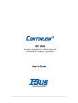
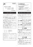
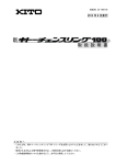
⑦
T2MCX6形 電動操作装置
取 扱 説 明 書
T2MCX6 Type Motor Operator
Operating Instructions
寺崎T2MCX6形電動操作装置付ブレ
ーカをお買上げ下さいましてありがとう
ございます。T2MCX6形電動操作装
置は,ブレーカのON-OFF(RESE
T)を電気操作する装置です。また手動操
作も可能です。
Thank you for purchasing the TERASAKI Circuit
Breaker with the typesT2MCX6 Motor Operator.
The type T2MCX6 Motor Operator motorizes the
breaker open/close(reset) operation.
The Operator also allows you to operate the
breaker manually.
Please read these Instructions carefully to ensure
correct use of the Operator.
This manual is to be delivered to the user after
completion of the installation work.
ご使用に際しましては本書をよくお読み
のうえ正しくご使用下さい。
工事が終わりましたら本説明書を需要家
様にお届け下さい。
■ 安全上のご注意
この取扱説明書では,
安全注意事項のランクを「危
険」,「注意」として区分してあります。
①
⑥
⑦
③ロックプレート
Be sure to read these Instructions and other associated
documents accompanying the product thoroughly to be
familiarize yourself with the product handling, safety
information, and all other precautions before mounting,
using, servicing, or inspecting the product.
In these Instructions, safety notices are divided into
"Warning" and "Caution" according to the hazard level:
施工,使用,保守・点検の前に,必ずこの取扱説
明書とその他の付属書類を熟読し,正しくご使用
下さい。機器の知識,安全の情報,そして注意事
項のすべてについて習熟してからご使用下さい。
②
③
④
Manual operating handle
①手動操作ハンドル
■ Safety Notices
⑤
Lock plate
⑦
1
②インジケータ
Indicator *
④制御回路端子
Control circuit terminals
⑥制御回路銘板
Control circuit nameplate
⑤電動操作装置銘板 Motor operator nameplate
⑦装置取付けねじ Mounting screws
*1 ブレーカの開閉状態を示します。ON:赤色表
示、OFF:緑色表示、トリップ:白色表示
Red: Breaker ON. Green: Breaker OFF. White: Breaker
TRIPPED.
Warning :A warning notice with this symbol indicates
危険 :取扱いを誤った場合に,危険な状況
that neglecting the suggested procedure
or practice could be fatal or result in
serious personal injury.
が起こりえて,死亡叉は重傷を受け
る可能性が想定される場合。
注意 :取扱いを誤った場合に,危険な状況
が起こりえて,中程度の傷害や軽傷
を受ける可能性が想定される場合及
び物的損害のみが想定される場合。
Caution :A caution notice with this symbol indicates
注意 に記載した事項でも、状況によ
なお、
っては、重大な結果に結びつく可能性があります。
いずれも重要な内容を記載していますので、必ず
守って下さい。
that neglecting the suggested procedure
or practice could result in moderate or
slight personal injury and/or property
damage.
Fig. 1. Outside View
図1
外観図
電動操作装置形式
Motor operator type
T2MCX6
適用ブレーカ機種
Applicable breaker type
S1250-NE,S1250-GE,S1600-NE,S1250-NN,S1600-NN
Note that failing to observe caution notices could result in
serious injury/damage in some situations. Because safety
notices contain important information, be sure to read and
observe them.
-1-
[1]施工上のご注意
-2-
[1] Installation Precautions
Caution
注意
(1) 電気工事は,有資格者(電気工事士)が行っ
て下さい。
(2) 配線作業は,上位遮断器等を切(OFF)に
し,充電していないことを確認して行って下
さい。感電の恐れがあります。
(3) 制御回路の端子ねじ(M3.5)は,標準締付
トルク〔0.88~1.18N・m〕で確実に
締付けて下さい。
ねじが緩み,火災の原因となります。
(4) 端子[E]は必ずアースして下さい。感電の
恐れがあります。
(5) 制御回路端子カバー(透明)は,結線後必ず
取り付けて下さい。
感電の恐れがあります。
(1)
(2)
(3)
(4)
(5)
Installation work must be performed by competent
persons.
Prior to commencing any work on the product, open
an upstream circuit breaker or the like to isolate all
sources of power/voltage.
Otherwise, electric shock may result.
Tighten the terminal screws (M3.5) for the control
circuit to the standard tightening torque of 0.88 to 1.18
N • m.
A screw loose could result in a fire.
Be sure to connect terminal E to ground.
Otherwise, electric shock may result.
After terminal connection, be sure to attach the
transparent cover for the control terminals.
Otherwise, electric shock may result.
[2] Operation
[2]操作
Warning
危険
(1) 充電端子部に触れないで下さい。
感電の恐れがあります。
注意
(1) 自動的にブレーカがトリップ(遮断)した場
合は,原因を取り除いてからON操作して下
さい。
火災の恐れがあります。
(2) 電気操作と手動操作を同時に行わないで下
さい。
誤動作の恐れ及び故障の原因となります。
(1)
Never touch live terminals.
Doing so may result in electric shock.
Caution
(1)
(2)
When the breaker trips open automatically, remove the
cause; then close the breaker.
Otherwise, a fire could result.
Do not try to perform motorized and manual operation
simultaneously.
Doing so may result in malfunction or failure of the
product.
表1
形式
Type
T2MCX6
ハンドル操作力 Handle Operating Force N
オン-オフ ON-OFF
170
リセット RESET
260
-3-
Table 1
ハンドル操作角度
Handle Operating Angle
Approx. 125°
Caution
注意
電気操作上のご注意
(1) 電気操作は必ず,操作可能電圧範囲内の電圧
を供給して下さい。
操作可能電圧
定格電圧の85%~110%
低電圧,過電圧は焼損の恐れがあります。
(2) モータは短時間定格品です。連続開閉回数
(ON-OFFを1回として)は最多10回
です。
その後は少なくとも15分以上の休止時間
を与えてモータを冷却して下さい。
焼損の恐れがあります。
(3) OFF操作時,3秒以内にブレーカがOFF
にならない時は,電源を切って下さい。
焼損の恐れがあります。
(4) 電動操作装置の耐電圧は,制御回路一括と端
子"E"間でAC1500V,1分間です。
(制御電圧がDC24Vの場合は,AC500
V,1分間)
過電圧は損傷の恐れがあります。
(5) 電動操作装置は必ず,ブレーカに装備して操
作してください。電動操作装置のみでの電気
操作は行わないで下さい。
損傷の恐れがあります。
手動操作上のご注意
(1) 手動操作ハンドルに過大な荷重を加えない
で下さい。
損傷の原因となります(表1を参照)。
①電気操作
Caution on motorized operation
(1)
(2)
(3)
(4)
(5)
Permissible ranges of operating voltage are as follow:
85 to 110% of the rated voltage
Undervoltage or overvoltage may cause burnout.
The motor is rated for short-time. Repeated
open/close operation should not exceed 10 times.
If repeated continuous open/close operation is
inevitable, a pause of at least 15 min. should be
provided after the repetitions of 10 times.
Otherwise, burnout could result.
If the breaker does not close within three seconds
after closing operation, turn off the operating voltage.
Otherwise, burnout could result.
The dielectric withstand voltage of the Motor Operator
is 1500 VAC for one minute between the control circuit
group and terminal E. (For control voltage of 24
VDC, the dielectric withstand voltage is 500 VAC for
one minute.)
Overvoltage may result in damage to the Operator.
Be sure to mount the Motor Operator on the breaker
before using the Operator.
Sole operation of the Operator may result in damage
to it.
Caution on manual operation
(1)
Do not apply excessive force to the manual operating
handle.
Doing so may cause damage to the Operator. (See
Table 1.)
① Motorized Operation
1-1. Closing Operation
Closing an external ON switch closes the breaker
within 0.06 second.
Drawing out the lock plate disables the breaker to
close.
To enable the breaker closing operation, push in the
lock plate securely.
1-1.ON操作
ONスイッチ(外部)を閉じると,0.06秒
以内にブレーカは閉(ON)となります。
ロックプレートが引き出されていると,電気回
路がOFFになりブレーカを閉路出来ません。
ロックプレートを確実に押し込んで下さい。
不足電圧引外し(UVT)付きブレーカの場合
は,UVTコイルが励磁されていなければ閉路
出来ません。
UVTに電源を印加し,120ms経過後ON
操作して下さい。
-4-
ONスイッチ(外部)はブレーカ閉路後,開に
して下さい。連続的に閉じられていると開路後
の再投入(閉路)が出来ません。
1-2.OFF操作
OFFスイッチ(外部)を閉じると,3秒以内
にブレーカは開路出来ます。
1-3.トリップ
過電流引外し装置,不足電圧引外し(UVT)
または電圧引外し(SHT)等が動作した場合,
ブレーカは自動的にトリップし,インジケータ
は白色を表示します。
1-4.RESET操作
・ブレーカがトリップした場合,OFF/
RESETスイッチ(外部)を閉じると,ブレ
ーカを3秒以内にリセット出来ます。
・熱動-電磁式ブレーカの熱動過電流引外し装置
によりトリップした場合,数分経過後にリセッ
トして下さい。
②手動操作
2-1.ON,OFF/RESET操作
・手動操作ハンドルを手前にワンストローク引く
(回転させる)ことにより,ブレーカを交互に
開閉路出来ます(表1を参照)。
・ロックプレートが引き出されていると,ハンド
ルの取り出しが出来ません。ロックプレートを
確実に押し込んで下さい。
・不足電圧引外し(UVT)付きブレーカの場合
は,UVTコイルが励磁されていなければ閉路
出来ません。
2-2.トリップ操作
・ブレーカの機構点検や警報スイッチの動作確認
を行う時,トリップボタンを押して下さい。
③自動追従機構
制御電源印加中に手動ハンドルを操作した場
合,ハンドル収納と同時に投入スプリングが自
動的に釈放したり,モータが駆動し投入スプリ
ングを蓄勢したりします。また無電源で手動ハ
ンドルを操作した後も,制御電源が印加される
と,同様な動作が行われますが,これらは故障
ではなく,次の電気操作に備えて機構を自動的
に追従させるためです。
The breaker with undervoltage trip device (UVT)
cannot be closed unless the UVT coil is excited. To
close such a breaker, apply voltage to the UVT and
wait for 120 milliseconds until doing closing operation.
Open an external ON switch after closing the breaker.
If the switch remains closed, the breaker cannot be
closed again after it is opened.
1-2. Opening Operation
Closing an external OFF switch opens the breaker
within three seconds.
1-3. Tripping Operation
When the overcurrent trip device, undervoltage trip
device (UVT), or shunt trip device (SHT) is activated,
the breaker trips open automatically and the indicator
shows white.
1-4. Reset Operation
The tripped breaker can be reset within three seconds
by closing an external OFF/RESET switch.
When the thermal-magnetic circuit breaker is tripped
by the thermal overcurrent trip device, wait for several
minutes before resetting the breaker.
④ロックインオフ
④ Lock-in Off
ロックプレートを引き出して,スリットに南京錠
を掛けると電動操作装置はOFF状態にロックさ
れ,ON操作できなくなります。ON状態の時,
ロックプレートは引き出せません。
When the lock plate is drawn out and padlocked, the Motor
Operator is locked so that the breaker cannot be closed.
When the breaker is closed, the lock plate cannot be drawn
out.
ロックプレート
Lock plate
南京錠はご用意下さい。
図2
Padlock not supplied.
ロックインオフ
Fig. 2. Lock-in Off
② Manual Operation
2-1. Closing and Opening/Reset Operation
Pull down the manual operating handle. The breaker
will close when it has been open, and open when
closed. (See Table 1.)
When the lock plate is drawn out, the manual
operating handle cannot be pulled down. To enable
manual operation, push in the lock plate securely.
The breaker with undervoltage trip device (UVT)
cannot be closed unless the UVT coil is excited.
2-2. Tripping operation
Use the trip button to check the breaker function or
alarm switch for normal operation.
〒547-0002 大阪市平野区加美東 7-2-10
7-2-10 Kamihigashi, Hiranoku, Osaka 547-0002, Japan
Tel: 81-6-6791-9323
Tel: 06(6791)9320
2G0801SAA(KRB-0586)
③ Automatic Spring Charge/Discharge
When the manual operating handle is pull down while
control voltage is applied to the Motor Operator, the closing
spring is automatically discharged or motor-charged
immediately after the handle is retracted. Turning on
control voltage after handle operation without control voltage
will also cause the same action. This mechanism is
provided to make the Operator ready for the next motorized
operation.
-5-
[3]電動操作装置の取外し,
取付け方法
電動操作装置はブレーカから取り外さないで下さ
い。保守・点検等で取外しの必要性が生じた場合
のみ次の手順により取り外して下さい。
注意
(1) 電気工事は,有資格者(電気工事士)が行っ
て下さい。
(2) 作業は,上位遮断器等を切(OFF)にし,
主回路及び制御回路が充電していないこと
を確認して行って下さい。感電の恐れがあり
ます。
(3) 電動操作装置裏面のハンドルキャッチには
直接手を触れないで下さい。
けがの恐れがあります。
(4) 電動操作装置のカバーは取り外さないで下
さい。
けがの恐れがあります。
(5) 制御回路の端子ねじ(M3.5)は,標準締付
トルク〔0.88~1.18N・m〕で確実に
締付けて下さい。
ねじが緩み,火災の原因となります。
(6) 制御回路端子カバー(透明)は,結線後必ず
もとどおりに取り付けて下さい。
感電の恐れがあります。
1) 電動操作装置をOFF状態にします。([2]
の操作を参照して下さい。)
2) 図1の制御回路端子④に接続されている電
線をはずします。
3) 図1のロックプレート③を引き出し,南京錠
で施錠([2]操作のロックインオフを参照
して下さい。)して下さい。
4) 図1の4カ所の装置取付けねじを抜き取り
ます
5) 電動操作装置をまっすぐ手前に取り外しま
す。
6) 取付けは,取外しの逆手順です。インジケー
タとブレーカがOFF状態であることを確
認して取り付けて下さい。もしインジケータ
がONになっていたら,ハンドルキャッチを
ドライバーの先などで押し下げて,インジケ
ータをOFFにしてから装着して下さい。
7)2~3回ON-OFF操作を行い,異常なく
動作することを確認して下さい。不足電圧引
外し(UVT)付ブレーカをON-OFFする
ときは,必ずUVTに定格電圧を印加して下
さい。
[3] How to Remove/Mount the
Motor Operator
The Motor Operator should not be removed from the
breaker except when maintenance, inspection, or the like
requires the Operator to be removed.
To remove the Operator, proceed as follows:
Caution
(1)
(2)
(3)
(4)
(5)
(6)
1)
2)
3)
4)
5)
6)
6)
-7-
Installation work must be performed by competent
persons.
Prior to commencing any work on the product, open an
upstream circuit breaker or the like to isolate all
sources of power/voltage.
Otherwise, electric shock may result.
Do not touch the handle catch on the back of the Motor
Operator.
Doing so may cause personal injury.
Do not remove the cover of the Motor Operator.
Doing so may cause personal injury.
Tighten the terminal screws (M3.5) for the control
circuit to the standard tightening torque of 0.88 to 1.18
N•m.
A screw loose could result in a fire.
After terminal connection, be sure to attach the
transparent cover for the control terminals.
Otherwise, electric shock may result.
Turn off the Motor Operator. (See Section
[2] Operation.)
Disconnect wires from terminals ④ ( Fig. 1).
Draw out lock plate ③ (Fig. 1). Padlock the
lock plate. (See Subsection ④ in Section [2]
Operation.)
Remove the four mounting screws (Fig. 1).
Draw out the Motor Operator straight to
remove it from the breaker.
To mount the Operator, check if both the
indicator and breaker are set to OFF. Then
mount the Operator in reverse order.
If the Operator indicator shows ON, push
down the handle catch with the tip of a
screwdriver or the like so that the indicator
shows OFF, before mounting the Operator on
the breaker.
Perform Close/Open operation a few times to
check if the Operator is in order. Be sure to
apply the rated voltage to the undervoltage trip
device (UVT) during Close/Open operation.
-6-