1
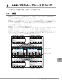
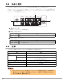
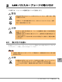
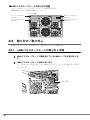
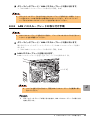
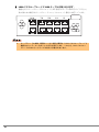
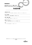
B7FY-1641-01
BX600
LAN パススルーブレード取扱説明書
GbE Pass-Thru Blade User’s Guide
(PG-LNB101)
J
E
はじめに
このたびは、弊社の BX600 LAN パススルーブレード(以降、本製品)をお買い上げいた
だき、誠にありがとうございます。
本製品は、PRIMERGY BX600 / BX600 S2 シャーシのネットワークブレードスロットに搭
載し、LAN(Local Area Network)システムの構築に使用します。
本書は、本製品の取り扱いの基本的な事柄について説明しています。ご使用になる前に、
本書をよくお読みになり、正しい取り扱いをされますようお願いいたします。
2005 年 11 月
安全にお使いいただくために
本書には、本製品を安全に正しくお使いいただくための重要な情報が記載されています。
本製品をお使いになる前に、本書を熟読してください。特に、本書の「安全上のご注意」をよくお読みにな
り、理解されたうえで本製品をお使いください。
また本書は、本製品の使用中にいつでもご覧になれるよう大切に保管してください。
注意
この装置は、情報処理装置等電波障害自主規制協議会(VCCI)の基準に基づく第二種情報技術装置です。こ
の装置を家庭環境で使用すると電波妨害を引き起こすことがあります。この場合には使用者が適切な対策を
講ずるよう要求されることがあります。
本製品のハイセイフティ用途での使用について
本製品は、一般事務用、パーソナル用、家庭用、通常の産業用等の一般的用途を想定して設計・製造されて
いるものであり、原子力施設における核反応制御、航空機自動飛行制御、航空交通管制、大量輸送システム
における運行制御、生命維持のための医療器具、兵器システムにおけるミサイル発射制御など、極めて高度
な安全性が要求され、仮に当該安全性が確保されない場合、直接生命・身体に対する重大な危険性を伴う用
途(以下「ハイセイフティ用途」という)に使用されるよう設計・製造されたものではございません。お客
様は、当該ハイセイフティ用途に要する安全性を確保する措置を施すことなく、本製品を使用しないでくだ
さい。ハイセイフティ用途に使用される場合は、弊社の担当営業までご相談ください。
当社のドキュメントには「外国為替および外国貿易管理法」に基づく特定技術が含まれていることがありま
す。特定技術が含まれている場合は、当該ドキュメントを輸出または非居住者に提供するとき、同法に基づ
く許可が必要となります。
2
本書の表記
■ 警告表示
本書ではいろいろな絵表示を使っています。これは装置を安全に正しくお使いいただ
き、あなたや他の人々に加えられるおそれのある危害や損害を未然に防止するための
目印となるものです。その表示と意味は次のようになっています。内容をよくご理解
の上、お読みください。
警告
この表示を無視して、誤った取り扱いをすると、人が死亡する可能
性または重傷を負う可能性があることを示しています。
注意
この表示を無視して、誤った取り扱いをすると、人が損害を負う可
能性があること、および物的損害のみが発生する可能性があること
を示しています。
また、危害や損害の内容がどのようなものかを示すために、上記の絵表示と同時に次
の記号を使用しています。
△で示した記号は、警告・注意を促す内容であることを告げるもの
です。記号の中やその脇には、具体的な警告内容が示されています。
で示した記号は、してはいけない行為(禁止行為)であることを
告げるものです。記号の中やその脇には、具体的な禁止内容が示さ
れています。
●で示した記号は、必ず従っていただく内容であることを告げるも
のです。記号の中やその脇には、具体的な指示内容が示されていま
す。
■ 本文中の記号
本文中に記載されている記号には、次のような意味があります。
記号
意味
お使いになる際の注意点や、してはいけないことを記述していま
す。必ずお読みください。
ハードウェアやソフトウェアを正しく動作させるために必要なこと
が書いてあります。必ずお読みください。
→
参照ページや参照マニュアルを示しています。
J
3
■ 製品の呼び方
本文中の製品名称を次のように略して表記します。
製品名称
本文中の表記
PRIMERGY BX600 LAN パススルーブレード
LAN パススルーブレード/本製品
PRIMERGY BX600 サーバブレード
BX600 サーバブレード
PRIMERGY BX660 サーバブレード
BX660 サーバブレード
PRIMERGY BX620 S2 サーバブレード
BX620 S2 サーバブレード
PRIMERGY BX600 シャーシ
PRIMERGY BX600 S2 シャーシ
サーバ
ブレード
シャーシ
安全上のご注意
本製品を安全にお使いいただくために、以降の記述内容を必ずお守りください。
警告
・ 機器を勝手に改造しないでください。火災・感電の原因となります。
・ 本体に水をかけたり、濡らしたりしないでください。火災・感電の原因となり
ます。
・ 近くで雷が発生した時は、本体の電源コードや本製品の外部接続コードを抜い
てください。そのまま使用すると、雷によっては機器を破壊し、火災の原因と
なります。
注意
・ 本製品は精密に作られていますので、高温・低温・多湿・直射日光など極端な
条件での使用・保管は避けてください。
またカードを曲げたり、傷つけたり、強いショックを与えないでください。
故障・火災の原因となることがあります。
・ ご使用にならない場合は、
静電気防止のために付属のカード袋へ入れて保管し
てください。
4
梱包物の確認
お使いになる前に、次のものが梱包されていることをお確かめください。
万一足りないものがございましたら、担当営業員または担当保守員にご連絡ください。
・ LAN パススルーブレード(本製品)
・ 保証書
・ 取扱説明書(本書)
J
All Rights Reserved, Copyright© FUJITSU LIMITED 2005
5
目次
1 LAN パススルーブレードについて . . . . . . . . . . . . . . . . . . . . . . .
7
1.2 名称と働き . . . . . . . . . . . . . . . . . . . . . . . . . . . . . . . . . . . . . . . . . . . . . . .
8
1.3 仕様 . . . . . . . . . . . . . . . . . . . . . . . . . . . . . . . . . . . . . . . . . . . . . . . . . . . .
2 LAN パススルーブレードの取り付け . . . . . . . . . . . . . . . . . . . . .
6
7
1.1 概要 . . . . . . . . . . . . . . . . . . . . . . . . . . . . . . . . . . . . . . . . . . . . . . . . . . . .
8
9
2.1 取り付ける前に . . . . . . . . . . . . . . . . . . . . . . . . . . . . . . . . . . . . . . . . . . .
9
2.2 取り付け/取り外し . . . . . . . . . . . . . . . . . . . . . . . . . . . . . . . . . . . . . . .
10
1
LAN パススルーブレードについて
この章では、本製品の特長、仕様について説明します。
1.1
概要
本製品は、サーバブレード内蔵 LAN ポート(LAN ドータカード含む)と外部 LAN ポー
トを 1 対 1 で接続する LAN パススルーブレードです。
本製品は、シャーシ背面のネットワークブレードスロットに搭載し、サーバブレードから
外部 LAN との間を接続します。サーバブレードとの接続用に 10 ポートの SERDES インタ
フェース(1Gbps 固定)と、外部 LAN 接続用に 10 ポートの 1000BASE-T Ethernet インタ
フェースを備えています。
本製品は、シャーシに最大 4 台増設できます。
次の図に、シャーシに、6 台の BX620 S2 サーバブレード(スロット 5 ~ 10 占有)と 2 台
の BX660 サーバブレード(スロット 1 ~ 4 占有)を搭載した構成例を示します。
本例では、各 LAN ポートからネットワークブレード間の LAN 接続を説明するため、すべ
てのサーバブレードに LAN ドータカードを搭載していますが、必ずしもすべてのサーバ
ブレードに LAN ドータカードを搭載する必要はありません。
1 2 3 4 5 6 7 8 9 10
1 2 3 4 5 6 7 8 9 10
PRIMERGY BX600
LANパススルーブレード
(NET 1)
PRIMERGY BX600
LANパススルーブレード
(NET 2)
1 2 3 4 5 6 7 8 9 10
1 2 3 4 5 6 7 8 9 10
1
2
3
4
5
6
7
8
9
10
a b
c d
a b
c d
a b
a b
a b
a b
a b
a b
オンボードLAN
PRIMERGY BX660
サーバブレード
(スロット1∼4まで計2台)
PRIMERGY BX620 S2
サーバブレード
(スロット5∼10まで計6台)
LANドータカード
AB
CD
AB
CD
AB
AB
AB
AB
AB
AB
1 2 3 4 5 6 7 8 9 10
1 2 3 4 5 6 7 8 9 10
PRIMERGY BX600
LANパススルーブレード
(NET 3)
PRIMERGY BX600
LANパススルーブレード
(NET 4)
1 2 3 4 5 6 7 8 9 10
1 2 3 4 5 6 7 8 9 10
J
1 LAN パススルーブレードについて 7
1.2
名称と働き
ここでは、LAN パススルーブレードの各部の名称と働きについて説明します。
LAN パススルーブレードには、LAN リンクランプと LAN アクティブランプが装備されて
います。これらの状態表示ランプにより、インストールとネットワークに関するトラブル
シューティングが容易になります。
3
9/10
7/8
5/6
3/4
1/2
1
2
1 ポート 1 ~ 10
RJ45 コネクタです(1000BASE-T)。
2 LAN リンクランプ
LED の状態
状態
点灯(Green) ポートがリンクされていないか、または無効に設定されています。
3 LAN アクティブランプ
LED の状態
状態
点滅(Amber) データ転送中です。
1.3
仕様
ここでは、LAN パススルーブレードの仕様について説明します。
項目
型名
I/O ポート
内部
10 ポート(1Gbps)
外部
10 ポート(1000BASE-T Ethernet, Full Duplex (固定)
)
コネクタ形状 RJ45 8 ピン
外形寸法(横幅×奥行き×高さ)
35 × 250 × 130(mm)(突起物は除く)
約 800g
質量
適用機種
`
8
仕様
PG-LNB101
BX600 シャーシ/ BX600 S2 シャーシ
LAN パススルーブレードを経由してハブ/ルータに接続する場合は、1000BASE-T
をサポートしているポートに接続してください。10BASE-T/100BASE-TX のみサ
ポートの場合は、通信できません。
2
LAN パススルーブレードの取り付け
この章では、シャーシへの搭載方法について説明します。
警告
・ 弊社の純正品以外のオプションは取り付けないでください。故障・発火・感電
の原因となります。
・ 内部のケーブル類や装置を傷つけたり、加工したりしないでください。故障・
発火・感電の原因となります。
注意
・ オプションを取り扱う場合には、シャーシの金属部分に触れて人体の静電気を
放電してください。
・ 基板表面や半田づけの部分に触れないように、金属の部分や基板の縁を持つよ
うにしてください。
・ この章で説明している以外の取り付け方や分解を行った場合は、保証の対象外
となります。
2.1
取り付ける前に
各 LAN パススルーブレードは、シャーシのメイン電源を入れた状態で取り付け/取り外
しができます。この場合、次の点に注意してください。
`
本製品に接続されているサーバブレードが動作中に、本製品を取り外すと LAN の接
続は失われます。
注意
・ 本製品およびダミースイッチブレードを取り外した際に、ネットワークブレー
ドスロット内に手を入れないでください。感電するおそれがあります。
・ ハンドルを上げる前に、本製品が奥まで差し込まれているか必ず確認してくだ
さい。
J
2 LAN パススルーブレードの取り付け 9
■ LAN パススルーブレードの取り付け位置
シャーシのネットワークブレードスロットに取り付けます。
BX600 S2 シャーシの場合を例に示します。
[シャーシ背面]
ネットワークブレード
スロット2
ネットワークブレード
スロット1
ネットワークブレード
スロット4
ネットワークブレード
スロット3
2.2
取り付け/取り外し
LAN パススルーブレードの取り付けと取り外しについての説明です。
2.2.1
LAN パススルーブレードの取り外し手順
1 LAN パススルーブレードに接続されている LAN ケーブルを取り外しま
す。
2 LAN パススルーブレードを取り外します。
ハンドルをつまんで引き出し(1)、LAN パススルーブレードを手前に引いて取り
外します(2)。
1
2
ハンドル
10
3 ダミースイッチブレード/ LAN パススルーブレードを取り付けます。
→「2.2.2 LAN パススルーブレードの取り付け手順」(P.11)
`
2.2.2
ダミースイッチブレードおよび LAN パススルーブレードを取り外した場合、シャー
シに空きスロットのある状態での運用は行わないでください。ダミースイッチブ
レードまたは LAN パススルーブレードを必ず取り付けてください。
LAN パススルーブレードの取り付け手順
`
LAN パススルーブレードを取り付ける前に、ブレードのコネクタにゴミなど付いて
いないことを必ず確認してください。
1 ダミースイッチブレード/ LAN パススルーブレードを取り外します。
取り付けるスロットのダミースイッチブレード/ LAN パススルーブレードを取り
外します。
→「2.2.1 LAN パススルーブレードの取り外し手順」(P.10)
2 LAN パススルーブレードを取り付けます。
LAN パススルーブレードを差し込み(1)
、ハンドルを収めます(2)
。
2
1
ハンドル
`
`
ハンドルを差し込んだあとに、再度 LAN パススルーブレードを確実に押し
込んでください。
J
ダミースイッチブレードの取り付け方法は、LAN パススルーブレードの取り付け
方法と同じです。
2 LAN パススルーブレードの取り付け 11
3 LAN パススルーブレードに LAN ケーブルを取り付けます。
接続を行うサーバブレードのスロットと同じ番号のポートに取り付けてください。
次の図の丸中数字はサーバブレードスロットのスロット番号に対応しています。
`
12
9/10
7/8
5/6
3/4
1/2
⑨
⑦
⑤
③
①
⑩
⑧
⑥
④
②
サーバブレードの有無、電源オン/オフ状態に関係なく LAN パススルーブレードと
接続されたハブ/ルータのリンク LED が点灯します。このとき、LAN パススルー
ブレードの LAN リンクランプは消灯する場合があります。
Before Reading This Manual
Thank you for purchasing the GbE Pass-Thru Blade (hereinafter referred to as this product).
This product can be installed in the network blade slot of the PRIMERGY BX600 S2 Blade Server
System Unit to configure the Local Area Network (LAN) system.
This manual explains standard operations about this product. Read this manual carefully to handle the
product correctly.
November 2005
For Your Safety
This manual contains important information, required to operate this product safely.
Thoroughly review the information in this manual before using this product. Especially note the points under "Safety",
and only operate this product with a complete understanding of the material provided.
This manual should be kept in an easy-to-access location for quick reference when using this product.
High Safety
The Products are designed, developed and manufactured as contemplated for general use, including without limitation,
general office use, personal use, household use, and ordinary industrial use, but are not designed, developed and
manufactured as contemplated for use accompanying fatal risks or dangers that, unless extremely high safety is secured,
could lead directly to death, personal injury, severe physical damage, or other loss (hereinafter "High Safety Required
Use"), including without limitation, nuclear reaction control in nuclear facility, aircraft flight control, air traffic control,
mass transport control, medical life support system, missile launch control in weapon system. You shall not use this
Product without securing the sufficient safety required for the High Safety Required Use. If you wish to use this Product
for High Safety Required Use, please consult with our sales representatives in charge before such use.
E
13
Remarks
Warning Descriptions
Various symbols are used throughout this manual. These are provided to emphasize important points
for your safety and that of others. The symbols and their meanings are as follows. Be sure to fully
understand these before reading this manual.
WARNING
Ignoring this symbol could be potentially lethal.
CAUTION
Ignoring this symbol may lead to injury and/or damage the device or hardware
options.
The following symbols are used to indicate the type of warning or cautions being described.
The triangle mark emphasizes the urgency of the WARNING and CAUTION.
Details are inside the triangle and above it.
A barred circle ( ) warns against certain actions (Do Not). These actions are
detailed inside the circle and above it.
A black circle indicates actions that must be taken.
These actions are detailed inside the black circle and above it.
Symbols
The following are symbols used throughout this manual.
Symbols
Meaning
These sections explain prohibited actions and points to note when using this
device. Make sure to read these sections.
These sections explain information needed to operate the hardware and
software properly. Make sure to read these sections.
→
This mark indicates reference pages or manuals.
Abbreviations
The following expressions and abbreviations are used to describe the product names used in this
manual.
Product name
14
Expressions and abbreviations
PRIMERGY BX600 GbE Pass-Thru Blade
GbE Pass-Thru Blade/This product
PRIMERGY BX600 Server Blade
BX600 Server Blade
PRIMERGY BX620 S2 Server Blade
BX620 S2 Server Blade
PRIMERGY BX600 S2 Blade Server System Unit
Chassis
Server
blade
Safety
For your safety and that of others, follow the guidelines provided on the following pages concerning
the use of this product.
WARNING
• Do not tinker with the product. Doing so may cause fire or electric shock.
• Keep the product away from water. Failure to do so may cause fire or electric
shock.
• When there is lightning nearby, unplug all power cords and external cords from
the product. Failure to do so may cause damage to the devices or fire.
CAUTION
• Since the product is delicate, avoid using or storing it under extreme conditions,
such as excessively high or low temperature, high humidity, or in direct sunlight.
Do not bend or damage the card or subject it to extreme shock. Doing so may
cause failure or fire.
• While not in use, store the card in the bag in which it was packaged to protect it
from static electricity.
E
15
Check the items supplied
Before using the product, check that no supplied or attached items are missing.
If any items are missing, contact an office listed in "Appendix A Contact Information" (Jpg.24).
• GbE Pass-Thru Blade (this product)
• GbE Pass-Thru Blade User's Guide (this manual)
All Rights Reserved, Copyright© FUJITSU LIMITED 2005
16
Contents
1 GbE Pass-Thru Blade . . . . . . . . . . . . . . . . . . . . . . . . . . . . . . .
18
1.1
Overview . . . . . . . . . . . . . . . . . . . . . . . . . . . . . . . . . . . . . . . . . . . . . .
18
1.2
Component Names and Functions . . . . . . . . . . . . . . . . . . . . . . . . . .
19
1.3
Specifications . . . . . . . . . . . . . . . . . . . . . . . . . . . . . . . . . . . . . . . . . . .
19
2 GbE Pass-Thru Blade Installation . . . . . . . . . . . . . . . . . . . . .
20
2.1
Before Installing GbE Pass-Thru Blade . . . . . . . . . . . . . . . . . . . . . . .
2.2
Installation and Removal . . . . . . . . . . . . . . . . . . . . . . . . . . . . . . . . . .
Appendix A
Contact Information . . . . . . . . . . . . . . . . . . . . . . .
20
21
24
E
17
1
GbE Pass-Thru Blade
This chapter explains the features and specifications of this product.
1.1
Overview
This product is a GbE Pass-Thru Blade which connects a server blade internal LAN port (including
Ethernet I/O Module) and an external LAN port on a one to one basis.
This product is installed to the network blade slot on the rear of chassis and connects the external
LAN and the server blade. This product has a 10 port SERDES interface (1Gbps fix) for connecting
the server blade, and a 10 port 1000BASE-T Ethernet interface for connecting external LAN.
A maximum of four of GbE Pass-Thru Blades can be added to a chassis.
The following chart shows an example when ten BX620 S2 Server Blades (taking slot no. 1 to 10) are
installed in the chassis.
In the following example, every server blade has an installed Ethernet I/O Module to explain the
LAN connection between each LAN port and network blade. However, it is not necessary to install
the module in every server blade.
1 2 3 4 5 6 7 8 9 10
1 2 3 4 5 6 7 8 9 10
PRIMERGY BX600
GbE Pass-Thru Blade
(NET 1)
PRIMERGY BX600
GbE Pass-Thru Blade
(NET 2)
1 2 3 4 5 6 7 8 9 10
1 2 3 4 5 6 7 8 9 10
1
2
3
4
5
6
7
8
9
10
a b
c d
a b
c d
a b
a b
a b
a b
a b
a b
Onboard LAN
PRIMERGY BX620 S2 Server Blades
Ethernet I/O Module
AB
18
CD
AB
CD
AB
AB
AB
AB
AB
AB
1 2 3 4 5 6 7 8 9 10
1 2 3 4 5 6 7 8 9 10
PRIMERGY BX600
GbE Pass-Thru Blade
(NET 3)
PRIMERGY BX600
GbE Pass-Thru Blade
(NET 4)
1 2 3 4 5 6 7 8 9 10
1 2 3 4 5 6 7 8 9 10
1.2
Component Names and Functions
This section explains the component names and functions of the GbE Pass-Thru Blade.
The GbE Pass-Thru Blade has LAN link LED and LAN active LED. These LEDs make
troubleshooting concering installation and networks easier.
3
9/10
7/8
5/6
3/4
1/2
1
2
1 Port 1 to 10
These are RJ45 connectors (1000BASE-T).
2 LAN link LED
LED status
Status
ON (Green)
The port is disabled or not linked.
3 LAN active LED
LED status
Blinking (Amber)
1.3
Status
Data is being transferred.
Specifications
This section explains the specifications of GbE Pass-Thru Blade.
Item
Product ID
I/O port
Internal
External
Dimension (Width × Depth × Height)
Weight
Applicable model
`
Specifications
PG-LNB101
10 ports (1Gbps)
10 ports (1000BASE-T Ethernet, Full Duplex (fix))
Connector configuration RJ45 8 pins
35 × 250 × 130 (mm) (not including the protruding parts)
About 800g
BX600 S2 Blade Server System Unit
When connecting hub/router via GbE Pass-Thru Blade, connect to the port
supporting 1000BASE-T. You cannot connect to the port only supporting 10BASE-T/
100BASE-TX.
E
1 GbE Pass-Thru Blade
19
2
GbE Pass-Thru Blade Installation
This chapter explains how to install this product into the chassis.
WARNING
• Do not install unauthorized third party options. Doing so may cause device
failure, fire, or electric shock.
• Do not damage or modify internal cables or devices. Doing so may cause device
failure, fire, or electric shock.
CAUTION
• Before handling options, first touch a metal part of the chassis to discharge static
electricity.
• Do not touch the circuitry boards or soldered parts. Hold the brackets or the
edges of the circuit boards.
• If devices are installed or removed by methods other than those outlined in this
chapter or disassembled, the warranty will become invalid.
2.1
Before Installing GbE Pass-Thru Blade
GbE Pass-Thru Blades can be installed/removed when the main power of the chassis is turned on. In
this case note the following points.
`
When the server blade connected to this product is operating, removing this product
will lose the LAN connection.
CAUTION
• When removing this product or a dummy switch blade, do not insert your hand
into the network blade slot. Doing so may cause electric shock.
• Before lifting the handle, make sure this product is inserted completely to the slot.
20
GbE Pass-Thru Blade installation points
Install this product in a network blade slot of the chassis.
[Rear of chassis]
Network blade
slot2
Network blade
slot1
Network blade
slot4
Network blade
slot3
2.2
Installation and Removal
This section explains how to install and remove the GbE Pass-Thru Blade.
2.2.1
How to remove the GbE Pass-Thru Blade
1 Remove all LAN cables connected to the GbE Pass-Thru Blade.
2 Remove the GbE Pass-Thru Blade.
Grip and pull out the handle (1), pull the GbE Pass-Thru Blade towards you and remove it
(2).
1
2
Handle
3 Install a dummy switch blade/GbE Pass-Thru Blade.
J"2.2.2 GbE Pass-Thru Blade Installation Procedure"(pg.22)
E
`
After removing the GbE Pass-Thru Blade or the dummy switch blade, do not operate
the chassis with an empty slot. Be sure to install a dummy switch blade or GbE PassThru Blade.
2 GbE Pass-Thru Blade Installation
21
2.2.2
GbE Pass-Thru Blade Installation Procedure
`
Before installing the GbE Pass-Thru Blade, make sure the blade connectors are
clean.
1 Remove the dummy switch blade/GbE Pass-Thru Blade.
Remove any existing dummy switch blade/GbE Pass-Thru Blade installed in the target slot.
J"2.2.1 How to remove the GbE Pass-Thru Blade"(pg.21)
2 Install the new GbE Pass-Thru Blade.
Insert the GbE Pass-Thru Blade (1) and restore the handle (2).
2
1
Handle
`
`
22
After restoring the handle, secure the GbE Pass-Thru Blade in place by
pressing it firmly.
The procedure for installing the dummy switch blade is the same as that for
installing the GbE Pass-Thru Blade.
3 Connect a LAN cable to the GbE Pass-Thru Blade.
Connect the LAN cable to the port whose number is the same as that of the server blade slot.
The numbers in the figure below correspond to the slot numbers of the server blade slot.
`
9/10
7/8
5/6
3/4
1/2
9
7
5
3
1
10
8
6
4
2
Regardless of the existence or non-existence of the server blade or power ON/OFF
status, hub/router link LED connecting to GbE Pass-Thru Blade turns on. During this
process, GbE Pass-Thru Blade LAN link LED may turn off.
E
2 GbE Pass-Thru Blade Installation
23
Appendix A Contact Information
• Australia:
Fujitsu Australia Limited
Tel: +61-2-9776-4555
Fax: +61-2-9776-4556
Address: 2 Julius Avenue (Cnr Delhi Road) North Ryde, Australia N.S.W. 2113
• China:
Fujitsu (China) Holdings Co., Ltd.
Tel: +86-21-5292-9889
Fax: +86-21-5292-9566
Address: 18F, Citic Square, 1168 West Nanjing Road Shanghai, China 200041
• Hong Kong:
Fujitsu Hong Kong Limited
Tel: +852-2827-5780
Fax: +852-2827-4724
Address: 10/F., Lincoln House, 979 King's Road Taikoo Place, Island East, Hong Kong
• Indonesia:
PT. Fujitsu Systems Indonesia Offices Headquarters
Tel: +62-21-570-9330 (Hunting)
Fax: +62-21-573-5150
Address: Wisma Kyoei Prince 10th Floor Jl. Jend. Sudirman Kav 3-4 Jakarta,
Indonesia 10220
• Korea:
Fujitsu Korea Ltd.
Tel: +82-2-3787-6000
Fax: +82-2-3787-6066
Address: Susong Tower Building, 83-1 Susong-Dong Jongno-Gu, Seoul,
Republic of Korea 110-140
• Malaysia:
Fujitsu (Malaysia) Sdn. Bhd.
Tel: +60-3-8318-3700
Fax: +60-3-8318-8700
Address: 1st Floor, No.3505 Jalan Technokrat 5 63000 Cyberjaya, Selangor Darul Ehsan Malaysia
• Philippines:
Fujitsu Philippines, Inc.
Tel: +63-2-812-4001
Fax: +63-2-817-7576
Address: 2nd Floor, United Life Building, A. Arnaiz Legaspi Village, Makati, Metro
Manila Philippines
24
• Singapore:
Fujitsu Asia Pte. Ltd.
Tel: +65-6777-6577
Fax: +65-6771-5502
Address: 20, Science Park Road, #03-01 TeleTech Park, Singapore Science Park II,
Singapore 117674
• Taiwan:
Fujitsu Taiwan Limited
Tel: +886-2-2311-2255
Fax: +886-2-2311-2277
Address: 19F, No.39, Section 1, Chung hwa Road Taipei, Taiwan
• Thailand:
Fujitsu Systems Business (Thailand) Ltd.
Tel: +66-2-500-1500
Fax: +66-2-500-1555
Address: 12th Floor, Olympia Thai Tower, 444 Rachadapisek Road Samsennok, Huaykwang,
Bangkok, Thailand 10310
• Vietnam:
Fujitsu Vietnam Limited
Tel: +84-4-831-3895
Fax: +84-4-831-3898
Address: Unit 802-8th floor, Fortuna Tower Hanoi 6B Lang ha Street, Ba dinh District, Hanoi
Socialist Republic of Vietnam
• United States:
Fujitsu Computer Systems Corporation
Tel: +1-800-831-3183
Fax: +1-408-496-0575
Address: 1250 East Arques Avenue, Sunnyvale, CA USA 94088-3470
For the latest information, refer to the Fujitsu PRIMERGY website (http://primergy.fujitsu.com).
E
Appendix A Contact Information
25
Memo
PRIMERGY BX600
LAN パススルーブレード(PG-LNB101)
取扱説明書
GbE Pass-Thru Blade(PG-LNB101)
User’s Guide
B7FY-1641-01-00
発行日
発行責任
2005 年 11 月
富士通株式会社
Issued on
Issued by
November, 2005
FUJITSU LIMITED
Printed in Japan
● 本書の内容は、改善のため事前連絡なしに変更することがあります。
● 本書に記載されたデータの使用に起因する、第三者の特許権およびその他の
権利の侵害については、当社はその責を負いません。
● 無断転載を禁じます。
● 落丁、乱丁本は、お取り替えいたします。
• The contents of this manual may be revised without prior notice.
• Fujitsu assumes no liability for damages to third party copyrights or other rights
arising from the use of any information in this manual.
• No part of this manual may be reproduced in any form without the prior written
permission of Fujitsu.
• Any manual which has missing pages or which is incorrectly collated will be
replaced.
P
こ のマ ニ ュ アルは リ サイ ク ルに配慮 し て製本 さ れています。
不要にな っ た際は、 回収 ・ リ サイ ク ルに出 し て く だ さ い。