1
3.1 Major Features and Components
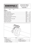
Fig. 1
Hydraulic
Cylinder
WARNING: Never attach the ATM-9 to a
joint until after the flange bolts have been
loosened and removed. Overloading may
occur if bolts are removed while the tool is installed,
and the resulting force is greater than the safe working
load of the tool.
ATM-9
Tool
Drop Leg
5.0 LIST OF EQUIPMENT
The tool set includes:
• ATM-9 alignment tool with hydraulic cylinder.
• Hydraulic hose, 6 feet [1,8 m] long.
• P-142 hydraulic hand pump.
• 3/8 inch NPTF couplers on hose, cylinder and pump.
• Ratchet and strap.
• Instruction sheet.
• Carrying case.
Hydraulic
Hose
Note: All hydraulic components are rated for 10,000
psi [700 bar] operation.
6.0 MISALIGNMENT DETERMINATION
PROCEDURE
• The ATM-9 must not be attached to a flanged joint
prior to the misalignment determination procedure
being carried out. Refer to warning statement in
section 4.0.
• Every second bolt should be loosened and removed.
Continue with this procedure. Misalignment may
not occur until only a few bolts remain. At this point
the direction of any misalignment should become
obvious.
• The ATM-9, once attached, will directly push against
the misalignment, bringing the joint back into
alignment.
Strap
P-142 Hydraulic Pump
3.2 Technical Data
Tool Description:
Aligning Force:
Hydraulic fixed flange
and rotational alignment
tool.
9.0 T [90 kN]
from 10,000 psi [700 bar]
of hydraulic pressure.
Example: Misalignment in various directions
A flanged joint, once broken down, may spring out of
alignment at any point, or in any direction around.
Note: Refer to section 18.0 for weights and dimensions.
4.0 SAFETY INFORMATION
See Fig. 2. The ATM-9 should be attached at the
maximum point of misalignment i.e. A or B. Each
example shows where ATM-9 should be attached.
IMPORTANT: In all installations the site safety
requirements must be adhered to. The safety of the
operator and any assisting personnel is of paramount
importance along with the safety of others including the
general public.
Fig. 2
These instructions are intended only to cover the safe
operation of ATM-9 during a normal maintenance and
installation operation. All other safety aspects must be
controlled by the operation supervisor.
CAUTION: The ATM-9 must not be attached
to pressure vessel nozzles.
3