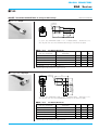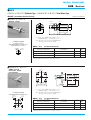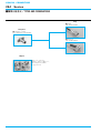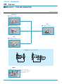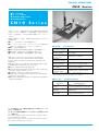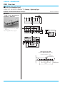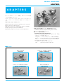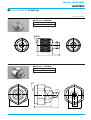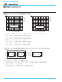
1
表紙折オモテ 608-1255
COAXIAL
CONNECTORS
RoHS対応品/RoHS Compliant
高周波同軸コネクタ
Japan Aviation Electronics Industry, Limited
〒153-8539 東京都目黒区青葉台3-1-19
(青葉台石橋ビル)
ホームページ ht tp: // www. jae. co. jp
お問い合わせは
「カスタマサポートグループ」へ
TEL(03)3780 - 2717・2817 FAX(03)3770 - 3869
大 阪 支 店 ・ 大 阪 市
TEL(06)
6447-5259 FAX(06)
6447-5276
中 部 支 店 ・ 豊 田 市
TEL(0565)
34-0600 FAX(0565)
34-0840
仙 台 営 業 所 ・ 仙 台 市
TEL(022)
225-8151 FAX(022)
225-8059
宇都宮営業所 ・ 宇 都 宮 市
TEL(028)
637-8545 FAX(028)
637-8546
静 岡 営 業 所 ・ 静 岡 市
TEL(054)
283-0664 FAX(054)
283-1993
福 岡 営 業 所 ・ 福 岡 市
TEL(092)
262-1888 FAX(092)
262-1750
2
0
0
6
COAXIAL CONNECTORS
2006
CAT.NO.COAX-006.SEP.2006
高
周
波
同
軸
コ
ネ
ク
タ
コネクタ情報 h t tp : // www.jae-connector.com
Japan Aviation Electronics Industry, Limited
1-19, Aobadai 3-chome, Meguro-ku, Tokyo 153-8539, Japan
Telephone:
(03)
3780-2768 Facsimile:
(03)
3780-2883
JAE Electronics, Inc.
142 Technology Drive, Suite 100 Irvine, California 92618-2430, U.S.A.
Telephone:
(1)
949-753-2600 Facsimile:
(1)949-753-2699
(800)
JAE-PART(523-7278)Toll free in U.S.A. except in California and Alaska
JAE Europe, Ltd.
Coliseum Business Center, Riverside Way, Camberley, Surrey GU15 3YL, U.K.
Telephone:
(44)1276-404000 Facsimile:
(44)1276-404010
JAE Taiwan, Ltd. <Taipei Branch Office>
4F-1, No.88, Sec.2, Chung Hsiao E.Rd., Taipei, Taiwan, R.O.C.
Telephone:
(886)2-2396-7676 Facsimile:
(886)2-2392-5929
JAE Hong Kong, Ltd.
Suites 1407-11,14/F., Tower2, The Gateway, 25 Canton Road,
Tsimshatsui, Kowloon, Hong Kong
Telephone:
(852)2723-7782 Facsimile:
(852)2723-9028
JAE Shanghai Co., Ltd.
RM1407, Shanghai Mart 2299 Yanan Road(West)Shanghai, 200336 P.R.C.
Telephone:
(86)
21-6236-0322 Facsimile:
(86)
21-6236-1292
JAE Singapore Pte Ltd.
33 Tannery Lane, #02-01 Hoesteel Industrial Building, Singapore 347789
Telephone:
(65)
6748-1332 Facsimile:
(65)
6748-2920
JAE Korea, Inc.
1602, City Air Tower, 159-9, Samsung-dong, Gangnam-gu, Seoul, 135-973 Korea
Telephone:
(82)2-551-8959 Facsimile:
(82)2-551-8958
このカタログは再生紙および環境にやさしい大豆インキを使用しています。
This catalogue is printed on recycled paper using SOY INK which is environmentally friendly.
本カタログ記載内容の無断転載を禁じます。
No part of this catalogue may be reproduced or distributed in any means, or stored in a data based
or retrieval system, without the prior written permission of Japan Aviation Electronics Industry,Ltd.
H1
H4
608-1255
日本航空電子工業(株)様 高周波同軸コネクタカタログ 06.09/05
土井
COAXIAL CONNECTORS
航空電子の
JAE
高周波同軸コネクタ
COAXIAL CONNECTOS
近年の各種電子機器は、デジタル化、高速化及び高周波化が進
展すると共に、情報通信分野での高周波対応の同軸伝送路技術
の革新が求められています。
特に、移動体通信機や携帯情報端末機によるモバイルコミュニ
ケーションの発展やマルチメディア、インターネット等の情報
ネットワークの構築、通信衛星によるグローバルな展開等、情
報通信分野での高周波伝送の応用はますます拡大しています。
In recent years advances have made in digitalization, increased
speed and frequency for various types of electronic equipment. At the
same time in the field of information communication, innovations are
being pursued in coaxial transmission circuit technology for high
frequencies.
航空電子は、航空・宇宙機器の高度な技術と幅広い分野で実績
のあるコネクション技術をベースに、これら高度情報通信時代
における高周波対応の同軸伝送ラインを、高性能、高信頼に接
続する同軸コネクタをお届け致します。
航空電子の同軸コネクタは、各種情報通信電子機器はもとより、
無線・有線通信装置、電子計測機器、放送機器など、幅広い電
子機器にご利用頂けます。
このカタログに掲載した製品以外でも製造しております。また、
お客様のご要望にて新規開発も承りますので、是非航空電子ま
でご一報下さい。
JAE has a foundation of solid business achievements in the high
performance technology of equipment for aerospace and
aeronautical use , as well as connection technology spanning a broad
range of fields. We can deliver coaxial connectors that link coaxial
transmission lines applicable to high frequencies in an age of highlevel information communication for top performance and reliability.
JAE coaxial connectors are being used more and more in an everwidening range of electronic equipment for all kinds of information
communication electronic equipment, in everything from wireless and
cable communication devices, electronic measuring instruments, and
broadcast equipment.
We manufacturer products other than those listed this catalog. We
also welcome requests from customers for new product development,
so please do not hesitate to contact us.
種類
汎用規格コネクタ
Type
General Purpose Standard Connectors
シリーズ名
Series Prefix
特性インピーダンス
Characteristic Impedance
適用周波数
Frequency Range
嵌合方式
Coupling Style
適合ケーブル
Applicable Cables
SMA
SMB
CN50
50Ω
50Ω
50Ω
DC to 18GHz
〔Straight Adapter〕
DC to 3GHz
DC to 3GHz
ネジカップリング
プッシュオン
プッシュオン
Threaded
Push-on
Push-on
1.5D-V, 1.5D-W, 2.5D-V,
UT141, UT85
1.5D-V, 1.5D-W, UT85
1.5D-V
500 VAC rms(1 minute)
500 VAC rms(1 minute)
200 VAC rms(1 minute)
500 megohms min.
500 megohms min.
500 megohms min.
外観
Appearance
耐電圧 D. W. Voltage
絶縁抵抗 Insulation Resistance
接触抵抗
Center Contact
4 milliohms max.
5 milliohms max.
15 milliohms max.
Contact
Resistance
Outer Contact
4 milliohms max.
2.5 milliohms max.
8 milliohms max.
1.2 max.(DC to 3GHz)
1.2 max.(DC to 3GHz)
1.2 max.(DC to 3GHz)
IEC60169-15
IEC60169-10
IEC60169-10 (Type SMB)
compatible
9 to 18
19 to 24
25 to 26
電圧定在波比
V.S.W.R.
準拠規格 Conformable Spc.
掲載頁 Page
2
COAXIAL CONNECTORS
目次 Contents
●製品概要 Introduction ........................................................2 to 7
●SMA Series............................................................................9 to 18
●SMB Series..........................................................................19 to 24
●CN50 Series .........................................................................25 to 26
●BNC Series...........................................................................27 to 34
●TNC Series ...........................................................................35 to 41
●N Series................................................................................43 to 49
●716 Series.............................................................................51 to 52
●CA1 Series............................................................................53 to 56
●CF2 Series ............................................................................57 to 61
●CN10 Series .........................................................................63 to 66
●KD10/KD20 Series ...............................................................67 to 69
●CV10 Series..........................................................................71 to 74
●CJ2 Series ............................................................................75 to 78
●CJ3 Series ............................................................................79 to 89
●CJ4 Series ............................................................................91 to 92
●ADAPTERS ...........................................................................93 to 107
●標準ハーネス品ご発注について
How to order for standard harness product ................109 to 111
●結線手順 Wire Connecting ............................................113 to 120
●付録・技術資料 Appendices .......................................121 to 136
●掲載品目一覧表 List of Part Number ..........................140 to 142
当社は、ISO9001(品質マネジメントシステム)及び
ISO14001(環境マネジメントシステム)の認証を取得し
ております。
JAE has been awarded the certificate of ISO9001(quality
management system)and ISO14001( environmental
management system).
汎用規格コネクタ
General Purpose Standard Connectors
BNC
TNC
N
716
50Ω/75Ω
50Ω
50Ω
50Ω
DC to 3GHz
DC to 3GHz
DC to 3GHz
バヨネットロック
ネジカップリング
ネジカップリング
ネジカップリング
Bayonet Lock
Threaded
Threaded
Threaded
0.8C-V, 1.5C-V, 1.5C-W,
1.5D-V, 1.5D-W, 2.5D-V, 3C-V
1.5D-V, 1.5D-W, 2.5D-V,
UT85
1.5D-V, 1.5D-W, 2.5D-V,
5D-V, UT141, UT85
2.5D-V
500 VAC rms(1 minute)
500 VAC rms(1 minute)
500 VAC rms(1 minute)
3000 VAC rms(1 minute)
500 megohms min.
500 megohms min.
500 megohms min.
10 gigaohms min.
10 milliohms max.
10 milliohms max.
10 milliohms max.
0.8 milliohms max.
5 milliohms max.
10 milliohms max.
10 milliohms max.
1.5 milliohms max.
1.2 max.(DC to 3GHz)
1.2 max.(DC to 3GHz)
1.2 max.(DC to 3GHz)
1.2 max.(DC to 3GHz)
IEC-60169-8
IEC60169-17
IEC60169-16
IEC60169-4
27 to 34
35 to 41
43 to 49
51 to 52
50Ω:DC to 4GHz
75Ω:DC to 2.4GHz
3
COAXIAL CONNECTORS
種類
オリジナルコネクタ
Type
JAE Original Connectors
シリーズ名
Series Prefix
特性インピーダンス
Characteristic Impedance
適用周波数
Frequency Range
嵌合方式
Coupling Style
適合ケーブル
Applicable Cables
CA1
CF2
CN10
50Ω
50Ω
50Ω
DC to 6GHz
DC to 6GHz
DC to 3GHz
プッシュオン
プラグイン
プッシュオン
Push-on
Plug-in
Push-on
1.5D-V, 1.5D-W, 2.5D-V,
UT141, UT85
1.5D-V, 1.5D-W,
UT141, UT85
0.8D-W, 1.5D-V,
1.5D-W, 2.5D-V
500 VAC rms(1 minute)
500 VAC rms(1 minute)
200 VAC rms(1 minute)
外観
Appearance
耐電圧 D. W. Voltage
絶縁抵抗 Insulation Resistance
1000 megohms min.
500 megohms min.
500 megohms min.
接触抵抗
Center Contact
4 milliohms max.
8 milliohms max.
8 milliohms max.
Contact
Resistance
Outer Contact
4 milliohms max.
8 milliohms max.
8 milliohms max.
1.2 max.(DC to 3GHz)
1.2 max.(DC to 3GHz)
1.2 max.(DC to 3GHz)
53 to 56
57 to 61
63 to 66
電圧定在波比
V.S.W.R.
掲載頁 Page
4
COAXIAL CONNECTORS
オリジナルコネクタ
JAE Original Connectors
KD10/KD20
CV10
CJ2
CJ3
50Ω/75Ω
50Ω
50Ω
50Ω
DC to 3GHz
DC to 3GHz
DC to 3GHz
プッシュオン
プッシュオン
プラグイン
プラグイン
Push-on
Push-on
Plug-in
Plug-in
50Ω : 0.8D-IEV or CO-6F-SB-CX50
75Ω : 0.8CV-E41447
0.8D EQUIVALENT
(SPECIAL)
0.8D-W, UT85
1.5D-V, 1.5D-W
250 VAC rms(1 minute)
500 VAC rms(1 minute)
500 VAC rms(1 minute)
500 VAC rms(1 minute)
100 megohms min.
500 megohms min.
1000 megohms min.
1000 megohms min.
80 milliohms max.
30 milliohms max.
50 milliohms max.
10 milliohms max.
30 milliohms max.
15 milliohms max.
20 milliohms max.
10 milliohms max.
1.3 max.(DC to 300MHz)
1.3 max.(DC to 3GHz)
1.3 max.(DC to 3GHz)
1.2 max.(DC to 3GHz)
67 to 69
71 to 74
75 to 78
79 to 89
DC to 300MHz
5
COAXIAL CONNECTORS
種類
オリジナルコネクタ
Type
JAE Original Connectors
シリーズ名
CJ4
Series Prefix
特性インピーダンス
Characteristic Impedance
適用周波数
50Ω
DC to 3GHz
Frequency Range
嵌合方式
プラグイン
Coupling Style
Plug-in
適合ケーブル
1.5D-V, 1.5D-W, UT85
Applicable Cables
外観
Appearance
耐電圧 D. W. Voltage
絶縁抵抗 Insulation Resistance
500 megohms min.
接触抵抗
Center Contact
10 milliohms max.
Contact
Resistance
Outer Contact
10 milliohms max.
電圧定在波比
V.S.W.R.
掲載頁 Page
6
500 VAC rms(1 minute)
1.2 max.(DC to 3GHz)
91 to 92
COAXIAL CONNECTORS
《参考/Reference》 ■適合ケーブル種類/表示方法について Applicable cable type / Description
ケーブルタイプ
Cable Type
絶縁体
標準外径(概略)
Standard outer
diameter of
insulator(approx.)
Flexible
0.8(mm)
1.5(mm)
2.5(mm)
3(mm)
5(mm)
10(mm)
Semi-flexible
―
Semi-rigid
―
標準外径(概略)
Standard
outer diameter
―
0.085(inch)
0.141(inch)
0.085(inch)
0.141(inch)
特性インピーダンス
Characteristic
Impedance
絶縁方式
Insulator
D:50Ω
C:75Ω
2:
ポリエチレン
充実形(注)
Filled
Polyethylene
(Note)
外部導体仕様
Specification of
outer conductor
ケーブルメーカー
商品名(例)
product name of
Cable maker
(examples)
V:1重編組
V:Single Braid
0.8D-IEV
1.5D-QEV
1.5D-GXC-SP
1.5D-HQ・SUPER
2.5D-GXC
2.5D-QEV
etc.
W:2重編組
W:Double Braid
50Ω
―
―
50Ω
―
―
1.5D-QEW
etc.
FCCA1
FCCAP0
VSC-086D
VSC-141D
(注)1.5D-GXC-SP、1.5D-HQ・SUPER、2.5D-GXCは除く。
(発泡ポリエチレン又は発泡ポリオレフィン)
(Note)Except 1.5D-GXC-SP, 1.5D-HQ・SUPER, 2.5D-GXC cables.(foamed polyethylene or foamed polyolefin)
(Example) 1.5 D − 2 V 相当(equivalent)
① ②
③ ④
①絶縁体標準外径(概略) :1.5mm
Standard outer diameter of
insulator(approx.)
②特性インピ−ダンス
:50Ω
Characteristic Impedance
③絶縁方式
Insulator
④外部導体仕様
:ポリエチレン充実形
Filled Polyethylene
:1重編組/Single Braid
Specification of
outer conductor
7
MEMO
8
COAXIAL CONNECTORS
SMA S e r i e s
■ DC∼18GHz(ストレートアダプタ)
■ ネジ結合式(1/4-36UNS)
■ FREQUENCY RANGE TO 18GHz(Straight adapter)
■ THREADED COUPLING(1/4-36UNS)
SMA
Series
SMAシリーズは、汎用規格(IEC60169-15)に準拠した、ネジ結
合タイプの小型同軸コネクタです。
機器内配線はもとより、機器を構成するサブアッセンブリ間及
び機器間の接続など、小スペースにて高密度実装を実現出来ます。
適用周波数はDC∼18GHz(ストレート型アダプタ)、VSWR(電
圧定在波比)が1.2以下の高性能型です。
●多様な実装形態に対応する、豊富な品種が揃っています。
特に、パネル実装用レセプタクルには豊富な品種が有ります。
●軽量・小型で堅牢構造です。
●接続の安定性及び高周波性能を重視した高信頼構造です。
●主な用途:移動体通信基地局、小型通信機器、精密計測機器
SMA series coaxial connectors are small size, with threaded coupling,
conforming to the general purpose standards(IEC60169-15).
It enables high density packaging inside equipment, as well as
compact interconnection between subassemblies and between units.
Applicable frequencies : from DC up to 18GHz(Straight adapter).
High performance with a VSWR of 1.2 or less.
●A wide variety of products, Panel mount receptacles, enable
diversified mount styles.
●Lightweight, compact in size and rugged construction.
●A high degree of reliability provides stable electric continuity and
high frequency performance.
●Applications: Base Station for Mobile Communications,
Communications Equipment, Measuring Instruments
3GHz以上の周波数に対応する製品も製作致します。
詳細は別途お問い合わせ下さい。
Products applicable over 3 GHz are available.
For detail, please consult us.
ケーブル接続タイプは、単体の他にお客様の仕様に合わせたハーネ
ス加工も行います。ハーネス加工のご発注については109∼111頁を
ご参照下さい。
In addition to independent cable application type, we also harness
products which satisfy your specification are available. Refer to
pages 109 to 111 for details.
■取扱説明書ご案内/Guide to Operation Manuals
本品をご使用時は、別途取扱説明書をご確認下さい。
・1.5D-V、1.5-D-Wケーブル :JAHL-2056-1
・2.5D-Vケーブル
:JAHL-2056-2
・0.141インチ/0.085インチ
セミフレキシブルケーブル:JAHL-2056-3
When using any of these products, please confirm the following
operation manuals.
・For 1.5D-V and 1.5D-W cables : JAHL-2056-1
・For 2.5D-V cables
: JAHL-2056-2
・For 0.141 and 0.085 inch
Semi-flexible cables
: JAHL-2056-3
■一般仕様 SPECIFICATIONS
特性インピーダンス
Characteristic Impedance
50Ω
Straight Adapter : DC to 18GHz
適用周波数(注)
Right Angle Adapter : DC to 12.4GHz
Frequency Range(Note)
Cable Harness : DC to 3GHz
耐電圧
D. W. Voltage
絶縁抵抗
Insulation Resistance
AC500Vr. m. s.(1 minute)
接触抵抗
Contact Resistance
Center Contacts : 4 milliohms max.
Outer Contacts : 4 milliohms max.
電圧定在波比
V. S. W. R.
適合ケーブル
Applicable Cables
1.2 max.(DC to 3GHz)
500 megohms min.(DC500V)
1.5D-V, 1.5D-W, 2.5D-V,
UT141, UT85
(注)パネル実装用及び基板実装用レセプタクルにつきましては、別途お問
い合わせ下さい。
(Note)For panel mount type and P.C.B.mount type receptacles,
please consult us.
■材料/仕上 MATERIALS/FINISHES
構成部品
Description
材料/仕上
Materials/Finishes
コンタクト
Contacts
インシュレータ
Insulator
銅合金/ニッケル上金メッキ
Copper Alloy/Gold Plated over Nickel
4フッ化エチレン
PTFE
シェル
Shell
銅合金/ニッケルメッキ又はステンレス鋼
Copper Alloy/Nickel Plated or
Stainless Steel
Semi-flexible Cable type :
銅合金/ニッケル上金メッキ
Copper Alloy/Gold over Nickel
カップリングナット
Coupling Nut
Oリング
O- ring
ステンレス鋼
Stainless Steel
ガスケット
Gasket
シリコンゴム(レンガ色)
Silicone Rubber(Brick Red)
Cリング
C- ring
フェルール
Ferrule
銅合金/ニッケルメッキ
Copper Alloy/Nickel Plated
銅合金/ニッケルメッキ
Copper Alloy/Nickel Plated
シリコンゴム(黒色)
Silicone Rubber(Black)
9
COAXIAL CONNECTORS
SMA S e r i e s
■種類と組合せ/TYPES AND COMBINATIONS
12 to 15 Pages
Receptacle
●Panel Mount・Straight
P/N:4 Hole Mount・SMAT001D00
P/N:2 Hole Mount・SMAT002D00
●Panel Mount・Right-angle
P/N:4 Hole Mount・SMAU001D00
Plug
●Through-hole Solder・Straight
P/N:SMAR001D00
●Straight
P/N:SMAA00※D**
●Through-hole Solder・Right-angle
P/N:SMAS001D00
●Right-angle
P/N:SMAB00※D**
Jack
●Bulkhead・Straight
P/N:SMAK00※D37
●Panel Mount・Straight
P/N:4 Hole Mount・SMAH00※D**
10
COAXIAL CONNECTORS
SMA S e r i e s
■種類と組合せ/TYPES AND COMBINATIONS
16 to 17 Pages
Plug Receptacle
●Panel Mount・Straight
P/N:4 Hole Mount・SMAP001D00
P/N:2 Hole Mount・SMAP002D00
Jack
●Straight
P/N:SMAF00※D**
●Panel Mount・Right-angle
P/N:4 Hole Mount・SMAQ001D00
Dust Cap
(For Receptacle & Jack)
Adapter
各種アダプタも有ります。
詳細は93∼107頁をご参照下さい。
Various adapters are available.
See pages 93 to 107.
See page 18
11
COAXIAL CONNECTORS
SMA S e r i e s
■RECEPTACLE
パネルマウントタイプ/Panel Mount Type
嵌合相手/Intermatable with PLUG(15 Page)
Dimensions in millimeters
■ストレート・4箇所ネジ止め式
Straight・Four-hole Mount
1/4-36UNS-2A
パネル取付穴寸法(参考)
PANEL MOUNTING HOLE PATTERNS(REF.)
+0.1
1.27±0.04
4.12±0.05
4-φ2.6 0
Part Number:SMAT001D00
4-M2.3×0.4
+0.1
φ4.15 0
1.7
9.5
0
4 −0.2
□8.64±0.1
6±0.1
□12.7
□8.64±0.1
15.5 Ref.
■ストレート・2箇所ネジ止め式
Straight・Two-hole Mount
+0.1
1/4-36UNS-2A
パネル取付穴寸法(参考)
PANEL MOUNTING HOLE PATTERNS(REF.)
2-φ2.6 0
φ4.12±0.05
2-M2.3×0.4
12.2±0.1
φ1.27
Part Number:SMAT002D00
1.7 4±0.2
9.5
+0.1
12.2±0.1
φ4.15 0
5.8
6±0.3
■ライトアングル・4箇所ネジ止め式
Right-angle・Four-hole Mount
1/4-36UNS-2A
Part Number:SMAU001D00
15.6
φ1.27±0.05
4-φ2.6 +0.2
0
1.7
7.1
12.85
4±0.2
6±0.3
8.64±0.1
12.7
パネル取付穴寸法(参考)
PANEL MOUNTING HOLE PATTERNS(REF.)
4-M2.3×0.4
+0.1
φ4.12 0
□8.64±0.1
12
COAXIAL CONNECTORS
SMA S e r i e s
■RECEPTACLE
基板スルーホールタイプ/Through-hole Solder Type
嵌合相手/Intermatable with PLUG(15 Page)
Dimensions in millimeters
■ストレート/Straight
1/4-36UNS-2A
基板取付穴寸法(参考・装着面)
PC BOARD LAYOUT・MOUNTING SIDE(REF.)
φ0.6±0.05
Part Number:SMAR001D00
4- 1±0.05
3.55
9.55
0.3
4- 1.4±0.05
5.08±0.1
4-φ1.6±0.1
φ1±0.1
5.08±0.1
φ9
2.6
■ライトアングル/Right-angle
Part Number:SMAS001D00
5.08±0.1
φ1.27
11.2
3.8
4- 1
15.6
6.4
( 6.08)
1/4-36UNS-2A
6.6
13.5
基板取付穴寸法(参考・装着面)
PC BOARD LAYOUT・MOUNTING SIDE(REF.)
5.08±0.1
5-φ1.6±0.1
13
COAXIAL CONNECTORS
SMA S e r i e s
■JACK
バルクヘッドタイプ/Bulkhead Type・パネルマウントタイプ/Panel Mount Type
嵌合相手/Intermatable with PLUG(15 Page)
Dimensions in millimeters
■バルクヘッド・ストレート
Bulkhead・Straight
φ11
1/4-36UNS-2A
2
0
5.9−0.1
0.6
9
11.1
パネル取付穴寸法(参考)
(パネル厚:1∼2mm)
PANEL MOUNTING HOLE PATTERNS(REF.)
(PANEL THICKNESS : 1 to 2mm)
2.2
A Ref.
(SHRINKAGE TUBE)
(注)上図は、品名:SMAK001D37で記載しています。
品名:SMAK002D37の場合、一部形状が異なります。
(Note)The picture on the above shows the SMAK001D37.
The shape varies slightly for the SMAK002D37.
+0.1
5.95 0
■品名/寸法 Part Number/Dimensions
+0.1
φ6.35 0
ケーブルタイプ(相当)
Cable Type(Equivalent)
品 名
Part Number
A
Ref.
1.5D-2V
SMAK001D37
−
1.5D-2W
SMAK002D37
20
(注)結線手順については、113∼120頁をご参照下さい。
(Note)Procedure for wire connection…See pages 113 to 120
■パネルマウント・ストレート
4箇所ネジ止め式
Panel mount・Straight
Four-hole Mount
4-M2.5×0.45
1/4-36UNS-2A
C
□8.7
□12.7
パネル取付穴寸法(参考)
PANEL MOUNTING HOLE PATTERNS(REF.)
A
1.7 B
D Ref.
(SHRINKAGE TUBE)
(注)上図は、品名:SMAH001D37で記載しています。
その他の品名の場合、一部形状が異なります。
(Note)The picture on the above shows the SMAH001D37.
The shapes of other models vary slightly.
φ6.5±0.1
■品名/寸法 Part Number/Dimensions
□8.7±0.1
4-φ2.8±0.1
ケーブルタイプ(相当)
Cable Type(Equivalent)
品 名
Part Number
A
B
C
D
Ref.
1.5D-2V
SMAH001D37
10.8
2.5
9
−
1.5D-2W
SMAH002D37
10.8
2.5
9
20
0.085 inch Semi-flexible
SMAH003DB2
17.8
1.5
5
13
(注)結線手順については、113∼120頁をご参照下さい。
(Note)Procedure for wire connection…See pages 113 to 120
14
COAXIAL CONNECTORS
SMA S e r i e s
■PLUG
嵌合相手/Intermatable with RECEPTACLE(12,13 Page)& JACK(14 Page)
Dimensions in millimeters
■ストレート/Straight
1/4-36UNS-2B
B
8HEX
C Ref.
A
(SHRINKAGE TUBE)
(注)上図は、品名:SMAA002D37で記載しています。その他の品名の場合、一部形状が異なります。
(Note)The picture on the above shows the SMAA002D37. The shapes of other models vary slightly.
■品名/寸法 Part Number/Dimensions
ケーブルタイプ(相当)
Cable Type(Equivalent)
品 名
Part Number
A
B
C
Ref.
1.5D-2V
SMAA002D37
12.6
19
−
1.5D-2W
SMAA003D37
12.6
19
20
2.5D-2V
SMAA001D13
12.4
10
−
0.141 inch Semi-flexible
SMAA007DA2
19.5
15
15
0.085 inch Semi-flexible
SMAA006DB2
19.9
15
13
(注)結線手順については、113∼120頁をご参照下さい。
(Note)Procedure for wire connection…See pages 113 to 120
■ライトアングル/Right-angle
1/4-36UNS-2B
16.2
B
C Ref.
(SHRINKAGE TUBE)
A
7.6
8HEX
(注)上図は、品名:SMAB002D37で記載しています。その他の品名の場合、一部形状が異なります。
(Note)The picture on the above shows the SMAB002D37. The shapes of other models vary slightly.
■品名/寸法 Part Number/Dimensions
ケーブルタイプ(相当)
Cable Type(Equivalent)
品 名
Part Number
A
B
C
Ref.
1.5D-2V
SMAB002D37
0.5
19
−
1.5D-2W
SMAB003D37
0.5
19
20
2.5D-2V
SMAB001D13
1.5
10
−
0.141 inch Semi-flexible
SMAB007DA2
0.5
15
15
0.085 inch Semi-flexible
SMAB004DB2
1.3
15
13
(注)結線手順については、113∼120頁をご参照下さい。
(Note)Procedure for wire connection…See pages 113 to 120
15
COAXIAL CONNECTORS
SMA S e r i e s
■JACK
嵌合相手/Intermatable with PLUG RECEPTACLE(17 Page)
Dimensions in millimeters
■ストレート/Straight
1/4-36UNS-2A
8HEX
B
A
C Ref.
(SHRINKAGE TUBE)
(注)上図は、品名:SMAF001D37で記載しています。
その他の品名の場合、一部形状が異なります。
(Note)The picture on the above shows the SMAF001D37.
The shapes of other models vary slightly.
■品名/寸法 Part Number/Dimensions
ケーブルタイプ(相当)
Cable Type(Equivalent)
品 名
Part Number
A
B
C
Ref.
1.5D-2V
SMAF001D37
11.8
9
−
1.5D-2W
SMAF002D37
11.8
9
20
2.5D-2V
SMAF003D13
12.8
10
−
(注)結線手順については、113∼120頁をご参照下さい。
(Note)Procedure for wire connection…See pages 113 to 120
16
COAXIAL CONNECTORS
SMA S e r i e s
■PLUG RECEPTACLE
パネルマウントタイプ/Panel Mount Type
嵌合相手/Intermatable with JACK(16 Page)
Dimensions in millimeters
■ストレート・4箇所ネジ止め式
Straight・Four-hole Mount
パネル取付穴寸法(参考)
PANEL MOUNTING HOLE
PATTERNS(REF.)
φ4.12±0.05
φ1.27±0.05
Part Number:SMAP001D00
4-φ2.6 +0.1
0
1/4-36UNS-2B
4-M2.3×0.4
φ4.15 +0.1
0
8HEX
4±0.2
1.7
12.7
□8.64±0.1
6±0.3
□12.7
□8.64±0.1
4-φ2.6 +0.1
0
Part Number:SMAP002D00
12.2±0.1
1.7
4±0.2
φ4.15 +0.1
0
12.2±0.1
φ4.12±0.05
8HEX
5.8
6±0.3
12.7
■ライトアングル・4箇所ネジ止め式
Right-angle・Four-hole Mount
2-M2.3×0.4
φ1.27
0.65±0.05
1/4-36UNS-2B
パネル取付穴寸法(参考)
PANEL MOUNTING HOLE
PATTERNS(REF.)
φ16
■ストレート・2箇所ネジ止め式
Straight・Two-hole Mount
1/4-36UNS-2B
8 HEX
Part Number:SMAQ001D00
パネル取付穴寸法(参考)
PANEL MOUNTING HOLE
PATTERNS(REF.)
φ4.12±0.05
17.9
φ1.27±0.05
4-M2.3×0.4
φ4.15 +0.1
0
□8.64±0.1
1.7
12.85
4±0.2
6±0.3
2
8.64±0.1
4-φ2.6 +0.1
0
12.7
17
COAXIAL CONNECTORS
SMA S e r i e s
■DUST CAP(For Receptacle & Jack)
Dimensions in millimeters
■チェーン付き
With Chain
51±6
φ8
Part Number:SMA0D00001-R
8.5
12.7
φ2.7
●材質:銅合金
Material:Copper Alloy
1/4-36UNS-2B
■六角ナットタイプ・チェーン付き
Hexagon Nut Type・With Chain
51±6
Part Number:SMAD001Z00
φ2.7
8.5
12.7
8 0
−0.3
●材質:銅合金
Material:Copper Alloy
8
1/4-36UNS-2B
■プラスチックタイプ
Plastic Type
φ7.8
Part Number:SMA0D00000
12 Ref.
●材質:PVC
Material:PVC
18
φ5.8±0.3
COAXIAL CONNECTORS
SMB S e r i e s
■ DC∼3GHz対応
■ プッシュオン結合式
■ FREQUENCY RANGE TO 3GHz
■ PUSH-ON COUPLING
SMB
Series
SMBシリーズは、汎用規格(IEC60169-10)をベースにした、プ
ッシュオン結合タイプの小型同軸コネクタです。
高周波信号の伝送及び機器内の高密度実装に対応する、パネル
対ケーブル、基板対ケーブル接続用コネクタです。
適用周波数は3GHzまでで、VSWR(電圧定在波比)が1.2以下の
高性能型です。
●軽量・小型で堅牢構造です。
●接続の安定性及び高周波性能に優れた高信頼構造です。
●確実で安定した接続状態が得られます。
●主な用途:自動車電話、各種通信機器、電子計測器
SMB series coaxial connectors are small size, push-on coupling type,
basis of the general purpose standards(IEC60169-10).
For panel to cable or board to cable application, achieving high
frequency signal transmission and high density packaging inside
equipment. Applicable frequencies : from DC up to 3GHz.
High performance with a VSWR(voltage standing wave ratio)of 1.2
or less(Straight plug).
●Lightweight, compact in size and rugged construction.
●A high degree of reliability provides stable electric continuity and
high frequency performance.
●Reliable and stable interconnection.
●Applications : Automobile Telephone, Communications Equipment,
Measuring Instruments
■一般仕様 SPECIFICATIONS
特性インピーダンス
Characteristic Impedance
適用周波数
Frequency Range
耐電圧
D. W. Voltage
絶縁抵抗
Insulation Resistance
接触抵抗
Contact Resistance
電圧定在波比
V. S. W. R.
適合ケーブル
Applicable Cables
50Ω
DC to 3GHz
AC500Vr.m.s.(1minute)
500 megohms min.(DC250V)
Center Contacts : 5 milliohms max.
Outer Contacts : 2.5 milliohms max.
1.2 max.(DC to 3GHz)
1.5D-V, 1.5D-W, UT85
■材料/仕上 MATERIALS/FINISHES
構成部品
Description
コンタクト
Contacts
材料/仕上
Materials/Finishes
銅合金/ニッケル上金メッキ
Copper Alloy/Gold Plated over Nickel
インシュレータ
Insulator
4フッ化エチレン又はSPS樹脂
PTFE or SPS
シェル
Shell
銅合金/ニッケルメッキ
Copper Alloy/Nickel Plated
SMBH003DB2, SMBK003DB2,
SMBA003DB2 :
銅合金/ニッケル上金メッキ
Copper Alloy/Gold Plated over Nickel
SMBS001D00 :
亜鉛合金/銅上ニッケルメッキ
Zinc Alloy/Nickel Plated over Copper
ケーブル接続タイプは、単体の他にお客様の仕様に合わせたハーネ
ス加工も行います。ハーネス加工のご発注については109∼111頁を
ご参照下さい。
In addition to independent cable application type, we also harness
products which satisfy your specification are available. Refer to
pages 109 to 111 for details.
■取扱説明書ご案内/Guide to Operation Manuals
本品をご使用時は、別途取扱説明書をご確認下さい。
・1.5D-V、1.5D-Wケーブル :JAHL-2237-1
・0.085インチ
セミフレキシブルケーブル:JAHL-2237-2
When using any of these products, please confirm the following
operation manuals.
・For 1.5D-V and 1.5D-W cables : JAHL-2237-1
・For 0.085 inch
Semi-flexible cables
: JAHL-2237-2
フェルール
Ferrule
六角ナット
Hexagon Nut
Cリング
C-ring
銅合金/ニッケルメッキ
Copper Alloy/Nickel Plated
スリーブ
Sleeve
銅合金/ニッケルメッキ
Copper Alloy/Nickel Plated
銅合金/ニッケルメッキ
Copper Alloy/Nickel Plated
銅合金/ニッケルメッキ
Copper Alloy/Nickel Plated
19
COAXIAL CONNECTORS
SMB S e r i e s
■種類と組合せ/TYPES AND COMBINATIONS
Receptacle
●Bulkhead・Straight
P/N:SMBV001D00
●Panel Mount・Straight
P/N:2 Hole Mount・SMBT001D00
Plug
●Through-hole Solder・Straight
P/N:SMBR001D00
●Straight
P/N:SMBA00※D**
●Through-hole Solder・Right-angle
P/N:Machined Type・SMBS002D00
P/N:Die-cast Type・SMBS001D00
●Right-angle
P/N:SMBB00※D**
Jack
●Bulkhead・Straight
P/N:SMBK00※D**
●Panel Mount・Straight
P/N:4 Hole Mount・SMBH00※D**
Adapter
各種アダプタも有ります。
詳細は93∼107頁をご参照下さい。
Various adapters are available.
See pages 93 to 107.
20
COAXIAL CONNECTORS
SMB S e r i e s
■RECEPTACLE
バルクヘッドタイプ/Bulkhead Type・パネルマウントタイプ/Panel Mount Type
嵌合相手/Intermatable with PLUG(24 Page)
Dimensions in millimeters
■バルクヘッド・ストレート
Bulkhead・Straight
φ7
0.6±0.1
φ3.66
M5×0.5
5.5 0
−0.3
0.8
6
■パネルマウント・ストレート
2箇所ネジ止め式
Panel mount・Straight
Two-hole Mount
パネル取付穴寸法(参考)
(パネル厚:2∼2.3mm)
PANEL MOUNTING HOLE PATTERNS(REF.)
(PANEL THICKNESS : 2 to 2.3mm)
M5×0.5
Part Number:SMBV001D00
2.4±0.1
5.4±0.3
6.8
5.3
1.7
9
2.8
φ3.2±0.1
φ0.6±0.1
φ3.66
1.7±0.2
6.9
2.8±0.2
5.3±0.3
パネル取付穴寸法(参考)
PANEL MOUNTING HOLE PATTERNS(REF.)
2-M2×0.4
φ3.3+0.1
0
12.2±0.1
2-φ2.4 +0.2
0
17.5
12.2±0.1
Part Number:SMBT001D00
21
COAXIAL CONNECTORS
SMB S e r i e s
■RECEPTACLE
基板スルーホールタイプ/Through-hole Solder Type
嵌合相手/Intermatable with PLUG(24 Page)
Dimensions in millimeters
■ストレート/Straight
φ3.66
4-□0.65±0.05
φ0.7±0.1
Part Number:SMBR001D00
7.3
2.8
基板取付穴寸法(参考・装着面)
PC BOARD LAYOUT・MOUNTING SIDE(REF.)
φ1.2
0
φ1 +0.1
□5.08±0.05
□5.7
□5.08±0.05
■ライトアングル・切削タイプ
Right-angle・Machined Type
φ3.66
φ0.7±0.1
6.3
9.2 Ref.
12 Ref.
Part Number:SMBS002D00
4-□0.65±0.05
5
□5.08±0.05
3.2
7.5
□5.7
基板取付穴寸法(参考・装着面)
PC BOARD LAYOUT・MOUNTING SIDE(REF.)
0
4-φ1.2 +0.1
0
φ1 +0.1
□5.08±0.05
■ライトアングル・ダイカストタイプ
Right-angle・Die-cast Type
φ3.66 Ref.
φ0.8
□5.9
□0.55
6.65
6.25 Ref.
Part Number:SMBS001D00
□5.08
5
3.2
7.5±0.5
基板取付穴寸法(参考・装着面)
PC BOARD LAYOUT・MOUNTING SIDE(REF.)
0
4-φ1.2 +0.1
0
φ1 +0.1
□5.08±0.05
22
COAXIAL CONNECTORS
SMB S e r i e s
■JACK
バルクヘッドタイプ/Bulkhead Type・パネルマウントタイプ/Panel Mount Type
嵌合相手/Intermatable with PLUG(24 Page)
Dimensions in millimeters
■バルクヘッド・ストレート
Bulkhead・Straight
φ6.5
M5×0.5
8HEX
A
10.2
B Ref.
1.7
(SHRINKAGE TUBE)
パネル取付穴寸法(参考)
(パネル厚:3mm以下)
PANEL MOUNTING HOLE PATTERNS(REF.)
(PANEL THICKNESS : 3mm Max.)
0
2 +0.1
0
φ5.1 +0.1
(注)上図は、品名:SMBK001D37で記載しています。
その他の品名の場合、一部形状が異なります。
(Note)The picture on the above shows the SMBK001D37.
The shapes of other models vary slightly.
■品名/寸法 Part Number/Dimensions
ケーブルタイプ(相当)
Cable Type(Equivalent)
品 名
Part Number
A
B
Ref.
1.5D-2V
SMBK001D37
9
−
1.5D-2W
SMBK002D37
9
20
0.085 inch Semi-flexible
SMBK003DB2
5
13
(注)結線手順については、113∼120頁をご参照下さい。
(Note)Procedure for wire connection…See pages 113 to 120
+0.2
4-φ2.4 0
φ7
φ3.66
■パネルマウント・ストレート
4箇所ネジ止め式
Panel mount・Straight
Four-hole Mount
パネル取付穴寸法(参考)
PANEL MOUNTING HOLE PATTERNS(REF.)
□8.64±0.1
1.7
□12.7
6.9
A
5
B Ref.
(SHRINKAGE TUBE)
(注)上図は、品名:SMBH001D37で記載しています。
その他の品名の場合、一部形状が異なります。
(Note)The picture on the above shows the SMBH001D37.
The shapes of other models vary slightly.
φ7.2 +0.1
0
4-M2×0.4
■品名/寸法 Part Number/Dimensions
□8.64±0.1
ケーブルタイプ(相当)
Cable Type(Equivalent)
品 名
Part Number
A
B
Ref.
1.5D-2V
SMBH001D37
9
−
1.5D-2W
SMBH002D37
9
20
0.085 inch Semi-flexible
SMBH003DB2
5
13
(注)結線手順については、113∼120頁をご参照下さい。
(Note)Procedure for wire connection…See pages 113 to 120
23
COAXIAL CONNECTORS
SMB S e r i e s
■PLUG
嵌合相手/Intermatable with RECEPTACLE(21,22 Page)& JACK(23 Page)
Dimensions in millimeters
φ6
■ストレート/Straight
A
B Ref.
(SHRINKAGE TUBE)
12.5
(注)上図は、品名:SMBA001D37で記載しています。
その他の品名の場合、一部形状が異なります。
(Note)The picture on the above shows the SMBA001D37.
The shapes of other models vary slightly.
■品名/寸法 Part Number/Dimensions
ケーブルタイプ(相当)
Cable Type(Equivalent)
品 名
Part Number
A
B
Ref.
1.5D-2V
SMBA001D37
9
−
1.5D-2W
SMBA002D37
9
20
0.085 inch Semi-flexible
SMBA003DB2
5
13
(注)結線手順については、113∼120頁をご参照下さい。
(Note)Procedure for wire connection…See pages 113 to 120
6
9.7
A
B Ref.
(SHRINKAGE TUBE)
0.5
6.8
φ6
■ライトアングル/Right-angle
(注)上図は、品名:SMBB001D37で記載しています。
その他の品名の場合、一部形状が異なります。
(Note)The picture on the above shows the SMBB001D37.
The shapes of other models vary slightly.
■品名/寸法 Part Number/Dimensions
ケーブルタイプ(相当)
Cable Type(Equivalent)
品 名
Part Number
A
B
C
Ref.
1.5D-2V
SMBB001D37
9
0.5
−
1.5D-2W
SMBB002D37
9
0.5
20
0.085 inch Semi-flexible
SMBB003DB2
5
0.5
13
(注)結線手順については、113∼120頁をご参照下さい。
(Note)Procedure for wire connection…See pages 113 to 120
24
COAXIAL CONNECTORS
CN50 S e r i e s
■ DC∼3GHz対応
■ プッシュオン結合式
■ FREQUENCY RANGE TO 3GHz
■ PUSH-ON COUPLING
CN50
Series
CN50シリーズは、IEC60169-10(Type SMB)規格と互換性を持
ったプリント基板対ケーブル接続用小型同軸コネクタで、プレ
ス加工部品を使用したローコストタイプです。
高周波信号伝送及び機器内高密度実装に対応しており、携帯電話
基地局、アクセスポイントの無線通信機器等に最適な製品です。
周波数は3GHzまでに対応、VSWR(電圧定在波比)が1.2以下の
高性能型です。
●プッシュオン結合タイプの小型軽量型です。
●ケーブルの結線は、製品毎の高周波バラツキ誤差が少ない圧
着結線式です。
●嵌合時実装高さ、9.5mmのロープロファイル設計です。
●接続の安定性及び高周波性能を重視した高信頼構造です。
●主な用途:移動体通信基地局、無線LANアクセスポイント、
無線通信機器、放送機器、電子計測器
CN50 series connectors are small sized coaxial connectors for board
to cable application, conforming to IEC60169-10(Type SMB).
Low cost with punched parts. For high frequency signal transmission
and high density packaging in the device.
Most suitable for mobile phone stations and radio communications
equipment at access points.
Applicable frequencies : from DC up to 3GHz. High performance with
a VSWR(voltage standing wave ratio)of 1.2 or less.
●Push-on coupling, compact and lightweight.
●Crimp cable termination with limited variation in high frequency.
●Low profile 9.5 mm high when mated.
●A high degree of reliability provides stable electric continuity and
high frequency performance.
●Applications : Base Station for Mobile Communications, Radio LAN
Access Point, Radio Communication Equipment,
Broadcasting Equipment, Measuring Instruments
■種類と組合せ/Types and Combinations
Receptacle
Cable Harness
P/N:CN50R01D00
■一般仕様 SPECIFICATIONS
特性インピーダンス
Characteristic Impedance
適用周波数
Frequency Range
耐電圧
D. W. Voltage
絶縁抵抗
Insulation Resistance
接触抵抗
Contact Resistance
電圧定在波比
V. S. W. R.
適合ケーブル
Applicable Cables
50Ω
DC to 3GHz
AC200Vr.m.s.(1minute)
500megohms min.(DC250V)
Center Contacts : 15milliohms max.
Outer Contacts : 8milliohms max.
1.2 max.(DC to 3GHz)
1.5D-V
■材料/仕上 MATERIALS/FINISHES
構成部品
Description
材料/仕上
Materials/Finishes
中心コンタクト
Center Contacts
銅合金/ニッケル上金メッキ
Copper Alloy/Gold Plated over Nickel
外部コンタクト
Outer Contacts
インシュレータ
Insulator
銅合金/ニッケルメッキ
Copper Alloy/Nickel Plated
合成樹脂
Synthetic Resin
スリーブ
Sleeve
銅合金/ニッケルメッキ
Copper Alloy/Nickel Plated
フェルール
Ferrule
銅合金/ニッケルメッキ
Copper Alloy/Nickel Plated
ケーブル接続タイプは、お客様の仕様に合わせて弊社にてハーネス
9.5 Ref.
加工してご提供致します。
尚、本カタログ記載の製品及びケーブル以外にても製作致しますの
Dimensions in millimeters
で、ご相談下さい。
For the cable application type, harnessed connectors which satisfy
your specification are supplied.
We can also provide connectors and cables other than those listed in
this catalog. For detail, please consult us.
25
COAXIAL CONNECTORS
CN50 S e r i e s
■RECEPTACLE
■PLUG
Dimensions in millimeters
2.8
5.08±0.05
55
0.
2.54±0.05
5.
φ3.66
0.75
Part Number:CN50R01D00
基板取付穴寸法(参考・装着面)
(基板厚:1.6mm)
PC BOARD LAYOUT・MOUNTING SIDE(REF.)
(PC BOARD THICKNESS : 1.6mm )
08
08
5.7
5.
■RECEPTACLE
基板スルーホール・ストレート
Through-hole Solder・Straight
5-φ1
+0.1
0
2.54±0.05
5.08±0.05
■PLUG
ライトアングル・ケーブルアッセンブリ
Right-angle・Cable Assembly
ケーブルタイプは、お客様の仕様に合わせ、弊社にてハーネス加工してご提供致します。
詳細は別途お問い合わせ下さい。
For Cable application type, harnessed connectors which satisfy your specification
are supplied. For details please consult us.
適合ケーブル:1.5D-2V相当
Applicable Cables:1.5D-2V Equivalent
13.8 Ref.
13.8 Ref.
L±5%
26
270゚
90゚
7.6 Ref.
180゚
0゚
COAXIAL CONNECTORS
BNC S e r i e s
■ DC∼4GHz(50Ωタイプ)
■バヨネットロック式
■ FREQUENCY RANGE TO 4GHz(50ΩType)
■ BAYONET COUPLING
BNC
Series
BNCシリーズは、汎用規格(IEC60169-8)に準拠した小型同軸コ
ネクタです。
嵌合は操作性に優れたワンタッチバヨネットロック式で、屋内
用機器の機器間接続など、挿抜回数の多い用途に最適です。
適用周波数はDC∼4GHz(50Ω)/DC∼2.4GHz(75Ω)までで、
VSWR(電圧定在波比)1.2以下(DC∼3GHz)の高性能型です。
●多様な実装形態に対応する、豊富な品種が揃っています。
●インピーダンス:50Ω、75Ωに対応する2種類が有ります。
●接続の安定性及び高周波性能に優れた高信頼構造です。
●主な用途:放送機器、各種AV機器、計測機器
BNC series are small size coaxial connectors, conforming to the
general purpose standards(IEC60169-8).
Easy to operate bayonet lock, best suited for connection between
indoor devices, involving frequent connecting and disconnecting.
Applicable frequencies : from DC up to 4GHz(50Ω)/DC up to 2.4GHz
(75Ω). High performance with a VSWR(voltage standing wave ratio)
of 1.2 or less(DC to 3GHz).
●A wide variety of products enable various mounting styles.
●Two impedance models are available: 50 and 75 ohms.
●A high degree of reliability provides stable electric continuity and
high frequency performance.
●Applications : Broadcasting Equipment, Various Audio-visual
Equipment, Measuring Instruments
■一般仕様 SPECIFICATIONS
特性インピーダンス
Characteristic Impedance
50Ω、75Ω(Note)
適用周波数
Frequency Range
50Ω:DC to 4GHz
75Ω:DC to 2.4GHz
耐電圧
D. W. Voltage
AC500Vr.m.s.(1minute)
絶縁抵抗
Insulation Resistance
接触抵抗
Contact Resistance
500 megohms min.(DC500V)
Center Contacts : 10 milliohms max.
Outer Contacts : 5 milliohms max.
電圧定在波比
V. S. W. R.
1.2 max.(DC to 3GHz)
適合ケーブル
Applicable Cables
0.8C-V, 1.5C-V, 1.5C-W, 1.5D-V,
1.5D-W, 2.5D-V, 3C-V
(注)コネクタの嵌合は、特性インピーダンスが同じ物(50Ω-50Ω又は75Ω75Ω)同士で行う事を推奨致します。
(Note)We recommend that you couple connectors with the same impedance(50Ω
to 50Ω or 75Ω to 75Ω).
■材料/仕上 MATERIALS/FINISHES
ケーブル接続タイプは、単体の他にお客様の仕様に合わせたハーネス
構成部品
Description
コンタクト
Contacts
加工も行います。ハーネス加工のご発注については109∼111頁をご
参照下さい。
In addition to independent cable application type, we also harness
products which satisfy your specification are available. Refer to pages
109 to 111 for details.
■取扱説明書ご案内/Guide to Operation Manuals
本品をご使用時は、別途取扱説明書をご確認下さい。
・0.8C-Vケーブル
:JAHL-20028-1
・1.5C-V、1.5C-W
1.5D-V、1.5D-Wケーブル :JAHL-20028-2
・2.5D-Vケーブル
:JAHL-20028-3
・3C-Vケーブル
:JAHL-20028-4
When using any of these products, please confirm the following
operation manuals.
・For 0.8C-V cables
: JAHL-20028-1
・For 1.5C-V, 1.5C-W,
1.5D-V and 1.5D-W cables
: JAHL-20028-2
・For 2.5D-V cables
: JAHL-20028-3
・For 3C-V cables
: JAHL-20028-4
インシュレータ
Insulator
シェル
Shell
ばね座金
Toothed Lock Washer
材料/仕上
Materials/Finishes
銅合金/ニッケル上金メッキ
Copper Alloy/Gold Plated over Nickel
4フッ化エチレン/PTFE
ライトアングルレセプタクルの一部:
ポリメチルペンテン
Part of Right-angle Receptacle :
Polymethlypentene
BNCS005C00 : PBT
銅合金/ニッケルメッキ
Copper Alloy/Nickel Plated
Right-angle Receptacle:
亜鉛合金/銅上ニッケルメッキ
Zinc Alloy/Nickel Plated over Copper
BNCS003C00 :
亜鉛合金/ニッケルメッキ
Zinc Alloy/Nickel Plated
ステンレス鋼/Stainless Steel
BNCS003C00:銅合金/ニッケルメッキ
Copper Alloy/Nickel Plated
六角ナット
Hexagon Nut
銅合金/ニッケルメッキ
Copper Alloy/Nickel Plated
スリーブ
Sleeve
フェルール
Ferrule
銅合金/ニッケルメッキ
Copper Alloy/Nickel Plated
銅合金/ニッケルメッキ
Copper Alloy/Nickel Plated
27
COAXIAL CONNECTORS
BNC S e r i e s
■種類と組合せ/TYPES AND COMBINATIONS
Receptacle
●Bulkhead・Straight
P/N:BNCV001D007
●Through-hole Solder・Straight
P/N:BNCR001D00
Jack
Plug
●Bulkhead・Straight
P/N:BNCK00※***
●Straight
P/N:BNCA00※***
●Panel Mount・Straight
P/N:4 Hole Mount・BNCH00※***
●Right-angle
P/N:BNCB00※***
●Through-hole Solder・Right-angle
P/N:BNCS002C00
●Through-hole Solder
Bulk Head・Right-angle
P/N:BNCS003C00
●Through-hole Solder
4 Contacts・Right-angle
P/N:BNCS005C00
Dust Cap
●For Receptacle & Jack
P/N:BNCD001Z00
Adapter
各種アダプタも有ります。
詳細は93∼107頁をご参照下さい。
Various adapters are available.
See pages 93 to 107.
28
COAXIAL CONNECTORS
BNC S e r i e s
■RECEPTACLE
バルクヘッドタイプ/Bulkhead Type・基板スルーホールタイプ/Through-hole Solder Type
嵌合相手/Intermatable with PLUG(33 Page)
1/2-28UNEF-2A
φ0.6±0.05
Part Number:BNCV001D00
1.8±0.1
8
14HEX
1.7±0.07
1±0.07
5.5±0.05
0.5±0.07
■バルクヘッド・ストレート
Bulkhead・Straight
Characteristic Impedance:50Ω
Dimensions in millimeters
5.5±0.07
φ14
5.8±0.12
19.5
パネル取付穴寸法(参考)
(パネル厚:1∼4mm)
PANEL MOUNTING HOLE PATTERNS(REF.)
(PANEL THICKNESS:1 to 4mm)
φ12.83 +0.12
0
5.54 +0.1
0
■基板スルーホール・ストレート
Through-hole Solder・Straight
Characteristic Impedance:50Ω
□10±0.1
4-□0.8±0.07
φ1.2±0.05
2.4
Part Number:BNCR001D00
11
0.3±0.1
14.4
φ15±0.25
2.6±0.2
基板取付穴寸法(参考・装着面)
PC BOARD LAYOUT・MOUNTING SIDE(REF.)
5-φ1.6±0.1
□10±0.1
■基板スルーホール・ライトアングル
Through-hole Solder・Right-angle
Characteristic Impedance:75Ω
11.02 Ref.
Part Number:BNCS002C00
基板取付穴寸法(参考・装着面)
PC BOARD LAYOUT・MOUNTING SIDE(REF.)
4-φ2.1 +0.1
0
□6.6±0.1
22.63
4-
1.
35
±
0.
08
□6.6±0.1
φ0.8±0.08
φ1.2 +0.1
0
φ10.3
2.6
29
COAXIAL CONNECTORS
BNC S e r i e s
■RECEPTACLE
基板スルーホールタイプ(バルクヘッド)/Through-hole Solder Type(Bulkhead)
嵌合相手/Intermatable with PLUG(33 Page)
Dimensions in millimeters
■ライトアングル/Right-angle
Characteristic Impedance:75Ω
11.07max.
Part Number:BNCS003C00
0
2-φ1.8 −0.1
34.93
20.83
1/2-28UNEF-2A
PRE-SOLDER
5.08±0.08
7.75
0
2-φ0.7 −0.08
2.8±0.3
0
φ0.7 −0.08
0.64
12.7
2.54±0.08
10.16±0.08
基板取付穴寸法(参考・装着面)
PC BOARD LAYOUT・MOUNTING SIDE(REF.)
添付品
Attached Parts
10.16±0.05
5.08±0.05
5.08±0.05
1/2-28UNEF-2B
2-φ2.01±0.08
2.54±0.05
2-φ0.89±0.08
14HEX
φ16
5.54 +0.05
0
30
φ12.83 +0.13
0
パネル取付穴寸法(参考)
(パネル厚:1∼4mm)
PANEL MOUNTING HOLE PATTERNS(REF.)
(PANEL THICKNESS : 1 to 4mm)
COAXIAL CONNECTORS
BNC S e r i e s
■RECEPTACLE
基板スルーホールタイプ(4極型)/Through-hole Solder Type(4 Contacts Type)
嵌合相手/Intermatable with PLUG(33 Page)
Dimensions in millimeters
■ライトアングル/Right-angle
Characteristic Impedance:75Ω
Part Number:BNCS005C00
(注)基板取付穴寸法については、別途お問い合わせ下さい。
(Note)For PC Board layout, please consult us.
12±0.15
17
34
51
65±0.28
14.9±0.1
42.5±0.06
3-M3×0.5
25.5±0.06
8.5±0.06
4-φ0.7 0
−0.1
PRE-SOLDER
2.6
CENTER CONDUCTOR
パネル取付穴寸法(参考)
(パネル厚:1mm)
PANEL MOUNTING HOLE PATTERNS(REF.)
(PANEL THICKNESS : 1mm)
42.5±0.05
4×10.4±0.1
25.5±0.05
8.5±0.05
1.75±0.05
3.3
4.2
4.4±0.06
3.3
6.15±0.06
2.8
BOSS
11±0.1
26.8 Ref.
4-φ12±0.1
17±0.05
34±0.05
51±0.05
3-φ3.4 +0.2
0
31
COAXIAL CONNECTORS
BNC S e r i e s
■JACK
バルクヘッドタイプ/Bulkhead Type・パネルマウントタイプ/Panel Mount Type
嵌合相手/Intermatable with PLUG(33 Page)
■バルクヘッド・ストレート
Bulkhead・Straight
Dimensions in millimeters
5.5 +0.04
−0.05
1/2-28UNEF-2A
14HEX
8
1
B
C Ref.
A
(
パネル取付穴寸法(参考)
(パネル厚:2∼4mm)
PANEL MOUNTING HOLE PATTERNS(REF.)
(PANEL THICKNESS : 2 to 4 mm)
φ12.83 +0.12
0
5.54 +0.1
0
SHRINKAGE
TUBE
)
(注)上図は、品名:BNCK002D37で記載しています。
その他の品名の場合、一部形状が異なります。
(Note)The picture on the above shows the BNCK002D37.
The shapes of other models vary slightly.
■品名/寸法 Part Number/Dimensions
ケーブルタイプ(相当)
Cable Type(Equivalent)
品 名
Part Number
Characteristic
Impedance
A
B
C
±2
1.5D-2V
BNCK002D37
50Ω
19
10
−
1.5D-2W
BNCK006D37
50Ω
19
19
21
2.5D-2V
BNCK003D13
50Ω
19
11
−
0.8C-2V
BNCK001C21
75Ω
20
18
−
(注)結線手順については、113∼120頁をご参照下さい。
(Note)Procedure for wire connection…See pages 113 to 120
■パネルマウント・ストレート
4箇所ネジ止め式
Panel mount・Straight
Four-hole Mount
4-φ3 +0.3
0
□12.7±0.1
□17.5
2.2
B
C Ref.
A
(
SHRINKAGE
TUBE
)
(注)上図は、品名:BNCH002D37で記載しています。
その他の品名の場合、一部形状が異なります。
(Note)The picture on the above shows the BNCH002D37.
The shapes of other models vary slightly.
パネル取付穴寸法(参考)
PANEL MOUNTING HOLE PATTERNS(REF.)
4-φ3 +0.2
0
φ12 +0.2
0
□12.7±0.1
■品名/寸法 Part Number/Dimensions
ケーブルタイプ(相当)
Cable Type(Equivalent)
品 名
Part Number
Characteristic
Impedance
A
B
C
Ref.
1.5D-2V
BNCH002D37
50Ω
20
19
−
1.5D-2W
BNCH005D37
50Ω
20
19
20
2.5D-2V
BNCH003D13
50Ω
20
10
−
0.8C-2V
BNCH001C21
75Ω
21
17
−
(注)結線手順については、113∼120頁をご参照下さい。
(Note)Procedure for wire connection…See pages 113 to 120
32
COAXIAL CONNECTORS
BNC S e r i e s
■PLUG
嵌合相手/Intermatable with RECEPTACLE(29 to 31 Page)& JACK(32 Page)
Dimensions in millimeters
■ストレート/Straight
φ14.3
B
A
C Ref.
(
SHRINKAGE
TUBE
)
(注)上図は、品名:BNCA003C37で記載しています。
その他の品名の場合、一部形状が異なります。
(Note)The picture on the above shows the BNCA003C37.
The shapes of other models vary slightly.
■品名/寸法 Part Number/Dimensions
ケーブルタイプ(相当)
Cable Type(Equivalent)
品 名
Part Number
Characteristic
Impedance
A
B
C
Ref.
1.5C-2V
BNCA003C37
75Ω
16
19
−
1.5C-2W
BNCA006C37
75Ω
16
19
20
1.5D-2V
BNCA002D37
50Ω
16
19
−
1.5D-2W
BNCA005D37
50Ω
16
19
20
3C-2V
BNCA004C61
75Ω
16
12
−
0.8C-2V
BNCA001C21
75Ω
18
17
−
(注)結線手順については、113∼120頁をご参照下さい。
(Note)Procedure for wire connection…See pages 113 to 120
■ライトアングル/Right-angle
22
19
(SHRINKAGE
)
TUBE
B
C Ref.
A
φ14.3
(注)上図は、品名:BNCB002C37で記載しています。
その他の品名の場合、一部形状が異なります。
(Note)The picture on the above shows the BNCB002C37.
The shapes of other models vary slightly.
■品名/寸法 Part Number/Dimensions
ケーブルタイプ(相当)
Cable Type(Equivalent)
品 名
Part Number
Characteristic
Impedance
A
B
C
Ref.
1.5C-2V
BNCB002C37
75Ω
7.8
19
−
1.5C-2W
BNCB005C37
75Ω
7.8
19
20
1.5D-2V
BNCB001D37
50Ω
7.8
19
−
1.5D-2W
BNCB004D37
50Ω
7.8
19
20
3C-2V
BNCB003C61
75Ω
8.8
12
−
(注)結線手順については、113∼120頁をご参照下さい。
(Note)Procedure for wire connection…See pages 113 to 120
33
COAXIAL CONNECTORS
BNC S e r i e s
■DUST CAP(For Receptacle & Jack)
Dimensions in millimeters
■プラスチックタイプ
Plastic Type
φ12
Part Number:BNCD001Z00
17 Ref.
●材質:PVC
Material:PVC
34
φ10
COAXIAL CONNECTORS
TNC S e r i e s
■ DC∼3GHz対応
■ネジ結合式(7/16-28UNEF)
■ FREQUENCY RANGE TO 3GHz
■ THREADED COUPLING(7/16-28UNEF)
TNC
Series
TNCシリーズは、汎用規格(IEC60169-17)に準拠したコンパク
ト設計で、ネジ結合タイプの中型同軸コネクタです。
適用周波数はDC∼3GHz、VSWR(電圧定在波比)が1.2以下の高
性能型です。
●多様な実装形態に対応する、豊富な品種が揃っています。
●環境特性を考慮した、堅牢で耐震構造の中型コネクタです。
●接続の安定性及び高周波性能に優れた高信頼構造です。
●主な用途:移動体通信基地局、通信機器、計測機器
TNC series middle size coaxial connectors conform to the general
purpose standards(IEC60169-17), designed with threaded coupling.
Applicable frequencies : from DC up to 3GHz. High performance with
a VSWR(voltage standing wave ratio)of 1.2 or less.
●A wide variety of products enable various mounting styles.
●Environmental middle size connectors with rugged vibration proof
construction.
●A high degree of reliability provides stable electric continuity and
high frequency performance.
●Applications : Base Station for Mobile Communications,
Communications Equipment, Measuring Instruments
3GHz以上の周波数に対応する製品も製作致します。
詳細は別途お問い合わせ下さい。
Products applicable up to abuout 3 GHz are available.
For detail, please consult us.
■一般仕様 SPECIFICATIONS
特性インピーダンス
Characteristic Impedance
適用周波数
Frequency Range
耐電圧
D. W. Voltage
絶縁抵抗
Insulation Resistance
接触抵抗
Contact Resistance
電圧定在波比
V. S. W. R.
適合ケーブル
Applicable Cables
50Ω
DC to 3GHz
AC500Vr.m.s.(1minute)
500 megohms min.(DC500V)
Center Contacts : 10 milliohms max.
Outer Contacts : 10 milliohms max.
1.2 max.(DC to 3GHz)
1.5D-V, 1.5D-W, 2.5D-V, UT85
■材料/仕上 MATERIALS/FINISHES
構成部品
Description
ケーブル接続タイプは、単体の他にお客様の仕様に合わせたハーネ
ス加工も行います。ハーネス加工のご発注については109∼111頁を
ご参照下さい。
In addition to independent cable application type, we also harness
products which satisfy your specification are available. Refer to
pages 109 to 111 for details.
■取扱説明書ご案内/Guide to Operation Manuals
本品をご使用時は、別途取扱説明書をご確認下さい。
・1.5D-V、1.5D-Wケーブル :JAHL-2050-1
・2.5D-Vケーブル
:JAHL-2050-2
・0.085インチ
セミフレキシブルケーブル:JAHL-2050-3
When using any of these products, please confirm the following
operation manuals.
・For 1.5D-V and 1.5D-W cables : JAHL-2050-1
・For 2.5D-V cables
: JAHL-2050-2
・For 0.085 inch
Semi-flexible cables
: JAHL-2050-3
材料/仕上
Materials/Finishes
コンタクト
Contacts
インシュレータ
Insulator
銅合金/ニッケル上金メッキ
Copper Alloy/Gold Plated over Nickel
4フッ化エチレン
PTFE
シェル
Shell
銅合金/ニッケルメッキ
Copper Alloy/Nickel Plated
六角ナット
Hexagon Nut
バネ座金
Toothed Lock Washer
銅合金/ニッケルメッキ
Copper Alloy/Nickel Plated
ステンレス鋼
Stainless Steel
Oリング
O-ring
ニトリルゴム及びシリコンゴム
(黒色)
NBR and Silicon Rubber(Black)
Cリング
C-ring
銅合金/ニッケルメッキ
Copper Alloy/Nickel Plated
スリーブ
Sleeve
銅合金/ニッケルメッキ
Copper Alloy/Nickel Plated
TNCA003DB2:銅合金/ニッケル上金メッキ
Copper Alloy/Gold Plated over Nickel
ガスケット
Gasket
フェルール
Ferrule
シリコンゴム(レンガ色)
Silicon Rubber(Brick Red)
銅合金/ニッケルメッキ
Copper Alloy/Nickel Plated
35
COAXIAL CONNECTORS
TNC S e r i e s
■種類と組合せ/TYPES AND COMBINATIONS
Receptacle
●Bulkhead・Straight
P/N:TNCV001D00
Plug
●Straight
P/N:TNCA00※D**
●Through-hole Solder・Straight
P/N:TNCR001D00
Jack
●Bulkhead・Straight
P/N:TNCK00※D**
●Right-angle
P/N:TNCB00※D**
●Panel Mount・Straight
P/N:4 Hole Mount・TNCH00※D**
Dust Cap
(For Receptacle & Jack)
Adapter
各種アダプタも有ります。
詳細は93∼107頁をご参照下さい。
Various adapters are available.
See pages 93 to 107.
See page 41
36
COAXIAL CONNECTORS
TNC S e r i e s
■RECEPTACLE
バルクヘッドタイプ/Bulkhead Type・基板スルーホールタイプ/Through-hole Solder Type
嵌合相手/Intermatable with PLUG(40 Page)
7/16-28UNEF-2A
13HEX
1.8±0.1
19.5
0.5±0.07
φ13
Part Number:TNCV001D00
1±0.07
4.8 0
−0.1
1.7±0.07
■バルクヘッド・ストレート
Bulkhead・Straight
Dimensions in millimeters
5.5±0.07
5.8±0.12
パネル取付穴寸法(参考)
(パネル厚:1∼4mm)
PANEL MOUNTING HOLE PATTERNS(REF.)
(PANEL THICKNESS : 1 to 4mm)
φ11.2 +0.1
0
4.8 +0.1
0
■基板スルーホール・ストレート
Through-hole Solder・Straight
□10±0.1
2.4
11
14.4
4-□0.8±0.07
φ1.2±0.05
Part Number:TNCR001D00
0.3±0.1
φ15±0.25
2.6±0.2
基板取付穴寸法(参考・装着面)
PC BOARD LAYOUT・MOUNTING SIDE(REF.)
5-φ1.6±0.1
□10±0.1
37
COAXIAL CONNECTORS
TNC S e r i e s
■JACK
バルクヘッドタイプ/Bulkhead Type
嵌合相手/Intermatable with PLUG(40 Page)
Dimensions in millimeters
■ストレート/Straight
0
4.8 −0.1
13HEX
7/16-28UNEF-2A
20
φ19
3.3
A±0.8
B Ref.
(SHRINKAGE TUBE)
(注)上図は、品名:TNCK001D37で記載しています。
その他の品名の場合、一部形状が異なります。
(Note)The picture on the above shows the TNCK001D37.
The shapes of other models vary slightly.
パネル取付穴寸法(参考)
(パネル厚:2∼5mm)
PANEL MOUNTING HOLE PATTERNS(REF.)
(PANEL THICKNESS : 2 to 5mm)
φ11.2 +0.1
0
4.8 +0.1
0
■品名/寸法 Part Number/Dimensions
ケーブルタイプ(相当)
Cable Type(Equivalent)
品 名
Part Number
A
1.5D-2V
TNCK001D37
19
―
1.5D-2W
TNCK004D37
19
19.9
2.5D-V
TNCK002D13
10
―
(注)結線手順については、113∼120頁をご参照下さい。
(Note)Procedure for wire connection…See pages 113 to 120
38
B
Ref.
COAXIAL CONNECTORS
TNC S e r i e s
■JACK
パネルマウントタイプ/Panel Mount Type
嵌合相手/Intermatable with PLUG(40 Page)
■ストレート・4箇所ネジ止め式
Straight・Four-hole Mount
Dimensions in millimeters
4-φ3 +0.3
0
7/16-28UNEF-2A
□12.7±0.1
2.2
A
20.3
□17.5
B Ref.
(SHRINKAGE TUBE)
パネル取付穴寸法(参考)
PANEL MOUNTING HOLE PATTERNS(REF.)
(注)上図は、品名:TNCH001D37で記載しています。
その他の品名の場合、一部形状が異なります。
(Note)The picture on the above shows the TNCH001D37.
The shapes of other models vary slightly.
4-φ3 +0.2
0
■品名/寸法 Part Number/Dimensions
φ12 +0.2
0
ケーブルタイプ(相当)
Cable Type(Equivalent)
品 名
Part Number
A
B
Ref.
□12.7±0.1
1.5D-2V
TNCH001D37
19
―
1.5D-2W
TNCH005D37
19
20
2.5D-2V
TNCH002D13
10
―
(注)結線手順については、113∼120頁をご参照下さい。
(Note)Procedure for wire connection…See pages 113 to 120
4-φ3 +0.2
0
7/16-2UNEF-2A
φ4±01
■ストレート・4箇所ネジ止め式
単体防水型
Straight・Four-hole Mount
Waterproof
Part Number:TNCH003DB2
□12.7±0.1
□17.5
3
5.2
13±0.1
23
(
SHRINKAGE
TUBE
)
適合ケーブル:0.085インチ セミフレキシケーブル相当
Applicable Cables:0.085inch Semi-flexible Cable Equivalent
パネル取付穴寸法(参考)
PANEL MOUNTING HOLE PATTERNS(REF.)
(注)結線手順については、113∼120頁をご参照下さい。
(Note)Procedure for wire connection…See pages 113 to 120
4-φ3 +0.2
0
φ5∼7
□12.7±0.1
39
COAXIAL CONNECTORS
TNC S e r i e s
■PLUG
嵌合相手/Intermatable with RECEPTACLE(37 Page)& JACK(38, 39 Page)
Dimensions in millimeters
■ストレート/Straight
7/16-28UNEF-2B
φ15
B
C Ref.
A±0.8
(SHRINKAGE
)
TUBE
(注)上図は、品名:TNCA001D37で記載しています。その他の品名の場合、一部形状が異なります。
(Note)The picture on the above shows the TNCA001D37. The shapes of other models vary slightly.
■品名/寸法 Part Number/Dimensions
ケーブルタイプ(相当)
Cable Type(Equivalent)
品 名
Part Number
A
±0.8
B
C
Ref.
1.5D-2V
TNCA001D37
16.4
19
−
1.5D-2W
TNCA005D37
16.4
19
20
2.5D-2V
TNCA002D13
16.4
10
−
0.085 inch Semi-flexible
TNCA003DB2
17.6
15
13
(注)結線手順については、113∼120頁をご参照下さい。
(Note)Procedure for wire connection…See pages 113 to 120
■ライトアングル/Right-angle
22.4±0.8
φ15
(
SHRINKAGE
TUBE
A
7/16-28UNEF-2B
B Ref.
)
8
19
(注)上図は、品名:TNCB001D37で記載しています。その他の品名の場合、一部形状が異なります。
(Note)The picture on the above shows the TNCB001D37. The shapes of other models vary slightly.
■品名/寸法 Part Number/Dimensions
ケーブルタイプ(相当)
Cable Type(Equivalent)
品 名
Part Number
A
B
Ref.
1.5D-2V
TNCB001D37
19
−
1.5D-2W
TNCB003D37
19
20
2.5D-2V
TNCB002D13
10
−
(注)結線手順については、113∼120頁をご参照下さい。
(Note)Procedure for wire connection…See pages 113 to 120
40
COAXIAL CONNECTORS
TNC S e r i e s
■DUST CAP(For Receptacle & Jack)
Dimensions in millimeters
■チェーン無し
Without Chain
7/16-28UNEF-2B
φ15
Part Number:TNCD001Z00
10
●材質:銅合金
Material:Copper Alloy
■チェーン付き
With Chain
5
.
t0
Part Number:TNC0D00003-R
.
Ref
45゚
9.8
14.5 Ref.
10.5 ref.
●材質:銅合金
Material:Copper Alloy
φ16
53.5±8
φ11.2 Ref.
φ15 Ref.
7/16-28UNEF-2B
41
MEMO
42
COAXIAL CONNECTORS
N Series
■ DC∼3GHz対応
■ ネジ結合式(5/8-24UNEF)
■ FREQUENCY RANGE TO 3GHz
■ THREADED COUPLING(5/8-24UNEF)
N
Series
Nシリーズは、汎用規格(IEC60169-16)に準拠した、ネジ結合タ
イプの中型同軸コネクタです。
適用周波数はDC∼3GHz、VSWR(電圧定在波比)が1.2以下の高
性能型です。
●多様な実装形態に対応する、豊富な品種が揃っています。
●環境特性を考慮した、堅牢構造です。
●接続の安定性及び高周波性能に優れた高信頼構造です。
●主な用途:移動体通信基地局、通信機器、計測機器
N series coaxial connectors are middle size with threaded coupling,
conforming to the general purpose standards(IEC60169-16).
Applicable frequencies : from DC up to 3GHz. High performance with
a VSWR(voltage standing wave ratio)of 1.2 or less.
●A wide variety of products enable various mounting styles.
●Environmental rugged construction.
●A high degree of reliability provides stable electric continuity and
high frequency performance.
●Applications : Base Station for Mobile Communications,
Communications Equipment, Measuring Instruments
3GHz以上の周波数に対応する製品も製作致します。
詳細は別途お問い合わせ下さい。
Products applicable up to about 3 GHz are available.
For detail, please consult us.
ケーブル接続タイプは、単体の他にお客様の仕様に合わせたハーネ
■一般仕様 SPECIFICATIONS
特性インピーダンス
Characteristic Impedance
適用周波数
Frequency Range
耐電圧
D. W. Voltage
絶縁抵抗
Insulation Resistance
接触抵抗
Contact Resistance
電圧定在波比
V. S. W. R.
適合ケーブル
Applicable Cables
■取扱説明書ご案内/Guide to Operation Manuals
本品をご使用時は、別途取扱説明書をご確認下さい。
・1.5D-V、1.5D-Wケーブル :JAHL-2073-1
・2.5D-Vケーブル
:JAHL-2073-2
・5D-Vケーブル
:JAHL-2073-3
・0.141インチ/0.085インチ
セミフレキシブルケーブル:JAHL-2073-4
When using any of these products, please confirm the following
operation manuals.
・For 1.5D-V and 1.5D-W cables : JAHL-2073-1
・For 2.5D-V cables
: JAHL-2073-2
・For 5D-V cables
: JAHL-2073-3
・For 0.141 and 0.085 inch
Semi-flexible cables
: JAHL-2073-4
DC to 3GHz
AC500Vr.m.s.(1minute)
500 megohms min.(DC500V)
Center Contacts : 10 milliohms max.
Outer Contacts : 10 milliohms max.
1.2 max.(DC to 3GHz)
1.5D-V, 1.5D-W, 2.5D-V, 5D-V,
UT141, UT85
■材料/仕上 MATERIALS/FINISHES
構成部品
Description
材料/仕上
Materials/Finishes
コンタクト
Contacts
銅合金/ニッケル上金メッキ
Copper Alloy/Gold Plated over Nickel
インシュレータ
Insulator
4フッ化エチレン
PTFE
銅合金/ニッケルメッキ
Copper Alloy/Nickel Plated
N00H005DA2,N00H004DB2の一部:
銅合金/ニッケル上金メッキ
Copper Alloy/Gold Plated over Nickel
銅合金/ニッケルメッキ
Copper Alloy/Nickel Plated
ス加工も行います。ハーネス加工のご発注については109∼111頁を
ご参照下さい。
In addition to independent cable application type, we also harness
products which satisfy your specification are available. Refer to
pages 109 to 111 for details.
50Ω
シェル
Shell
カップリングナット
Coupling Nut
ガスケット
Gasket
Cリング
C-ring
シリコンゴム(レンガ色)
Silicon Rubber(Brick Red)
Oリング
O-ring
ニトリルゴム及びシリコンゴム
NBR and Silicon Rubber
銅合金/ニッケルメッキ
Copper Alloy/Nickel Plated
N00A001DA2:ニッケル上金メッキ
N00A001DA2:Gold Plated over Nickel
銅合金/ニッケルメッキ
Copper Alloy/Nickel Plated
銅合金/ニッケルメッキ
Copper Alloy/Nickel Plated
ステンレス鋼
Stainless Steel
スリーブ
Sleeve
フェルール
Ferrule
六角ナット
Hexagon Nut
バネ座金
Toothed Lock Washer
銅合金/ニッケルメッキ
Copper Alloy/Nickel Plated
43
COAXIAL CONNECTORS
N Series
■種類と組合せ/TYPES AND COMBINATIONS
Receptacle
●Panel Mount・Straight
P/N:4 Hole Mount・N00T001D00
Jack
Plug
●Bulkhead・Straight
P/N:N00K00※D37
●Straight
P/N:N00A※D**
●Bulkhead・Right-angle
P/N:N00L001D13
●Right-angle
P/N:N00B00※D**
●Panel Mount・Straight
P/N:4 Hole Mount・N00H00※D**
Dust Cap
(For Receptacle & Jack)
Adapter
各種アダプタも有ります。
詳細は93∼107頁をご参照下さい。
Various adapters are available.
See pages 93 to 107.
See page 49
44
COAXIAL CONNECTORS
N Series
■RECEPTACLE
パネルマウントタイプ/Panel Mount Type
嵌合相手/Intermatable with PLUG(48 Page)
■ストレート・4箇所ネジ止め式
Straight・Four-hole Mount
Dimensions in millimeters
4-φ3.2 +0.1
0
φ28
Part Number:N00T001D00
19±0.1
17
27
2
9±0.05
3
パネル取付穴寸法(参考)
PANEL MOUNTING HOLE PATTERNS(REF.)
4-M3×0.5
φ4.2 +0.1
0
19±0.05
11±0.1
+0.02
φ4.04 −0.05
φ1.27
5/8-24UNEF-2A
11±0.05
45
COAXIAL CONNECTORS
N Series
■JACK
バルクヘッドタイプ/Bulkhead Type
嵌合相手/Intermatable with PLUG(48 Page)
Dimensions in millimeters
■ストレート/Straight
5/8-24UNEF-2A
9
19HEX
23
3
A Ref.
(SHRINKAGE TUBE)
パネル取付穴寸法(参考)
(パネル厚:2∼4mm)
PANEL MOUNTING HOLE PATTERNS(REF.)
(PANEL THICKNESS : 2 to 4mm)
φ18.2 +0.2
0
(注)上図は、品名:N00K001D37で記載しています。
品名:N00K002D37の場合、一部形状が異なります。
(Note)The picture on the above shows the N00K001D37.
The Shapes varies slightly for the N00K002D37.
■品名/寸法 Part Number/Dimensions
16.4 +0.2
0
ケーブルタイプ(相当)
Cable Type(Equivalent)
品 名
Part Number
A
Ref.
1.5D-2V
N00K001D37
−
1.5D-2W
N00K002D37
20
(注)結線手順については、113∼120頁をご参照下さい。
(Note)Procedure for wire connection…See pages 113 to 120
■ライトアングル/Right-angle
Part Number:N00L001D13
適合ケーブル:2.5D-2V相当
Applicable Cables:2.5D-2V Equivalent
パネル取付穴寸法(参考)
(パネル厚:2∼4mm)
PANEL MOUNTING HOLE PATTERNS(REF.)
(PANEL THICKNESS : 2 to 4mm)
10
26
5/9-24UNEF-2A
19HEX
23 Ref.
33 Ref.
φ18.2 +0.2
0
(注)結線手順については、113∼120頁をご参照下さい。
(Note)Procedure for wire connection…See pages 113 to 120
16.4 +0.2
0
46
COAXIAL CONNECTORS
N Series
■JACK
パネルマウントタイプ/Panel Mount Type
嵌合相手/Intermatable with PLUG(48 Page)
■ストレート・4箇所ネジ止め式
Straight・Four-hole Mount
Dimensions in millimeters
【パネル側Oリング無しタイプ】
Without panel side O ring
4-φ3.4 +0.2
0
5/8-24UNEF-2A
□18.24±0.1
A±0.2
□25.4
9
B Ref.
(SHRINKAGE TUBE)
26
【パネル側Oリング付きタイプ】
With panel side O ring
4-φ3.4 +0.2
0
φ12±0.1
5/8-24UNEF-2A
パネル取付穴寸法(参考)
PANEL MOUNTING HOLE PATTERNS(REF.)
4-M3×0.5
3±0.2
□18.24±0.1
□25.4
26
A
6.1
B Ref.
(SHRINKAGE TUBE)
0
φ12.2 +0.2
(注)上図は、Oリング無し品名:N00H001D37、Oリング付き品名:N00H006D37で記載しています。
その他の品名の場合、一部形状が異なります。
(Note)The picture on the above shows the N00H001D37(without O ring)/N00H006D37(with O ring)
.
The shapes of other models vary slightly.
□18.24±0.1
■品名/寸法 Part Number/Dimensions
ケーブルタイプ(相当)
Cable Type(Equivalent)
1.5D-2V
1.5D-2W
品 名
Part Number
パネル側Oリング有無
Panel Side O Ring
A
B
Ref.
N00H001D37
×
―
―
N00H006D37
○
19
―
N00H002D37
×
―
20
N00H007D37
○
19
20
2.5D-2V
N00H003D13
○
10
―
0.141 inch Semi-flexible
N00H005DA2
○
15
15
0.085 inch Semi-flexible
N00H004DB2
○
15
13
(注)結線手順については、113∼120頁をご参照下さい。
(Note)Procedure for wire connection…See pages 113 to 120
47
COAXIAL CONNECTORS
N Series
■PLUG
嵌合相手/Intermatable with RECEPTACLE(45 Page)& JACK(46, 47 Page)
φ17.5
5/8-24UNEF-2B
φ21
■ストレート/Straight
Dimensions in millimeters
A
26 Ref.
(注)右図は、品名:N00A002D51で記載して
います。
品名:N00A001DA2の場合、一部形状が
異なります。
(Note)The picture on the right shows the
N00A002D51.
The shapes varies slightly for the
N00A001DA2.
B Ref.
(SHRINKAGE TUBE)
■品名/寸法 Part Number/Dimensions
ケーブルタイプ(相当)
Cable Type(Equivalent)
品 名
Part Number
A
B
Ref.
5D-2V
N00A002D51
15
20
0.141 inch Semi-flexible
N00A001DA2
15
―
(注)結線手順については、113∼120頁をご参照下さい。
(Note)Procedure for wire connection…See pages 113 to 120
22.7
5.3
17.5
4
9
A Ref.
(SHRINKAGE TUBE)
5/8-24UNEF-2B
φ21
■ライトアングル/Right-angle
(注)上図は、品名:N00B001D37で記載しています。その他の品名の場合、一部形状が異なります。
(Note)The picture on the above shows the N00B001D37. The shapes of other models vary slightly.
【Part Number:N00B004D51】
7.3
15
18
φ21
18
30 Ref.
2
(SHRINKAGE TUBE)
24.5
5/8-24UNEF-2B
■品名/寸法 Part Number/Dimensions
ケーブルタイプ(相当)
Cable Type(Equivalent)
品 名
Part Number
A
B
Ref.
1.5D-2V
N00B001D37
19
―
1.5D-2W
N00B002D37
19
20
2.5D-2V
N00B003D13
10
―
5D-2V
N00B004D51
―
―
(注)結線手順については、113∼120頁をご参照下さい。
(Note)Procedure for wire connection…See pages 113 to 120
48
COAXIAL CONNECTORS
N Series
■DUST CAP(For Receptacle & Jack)
Dimensions in millimeters
■Part Number:N000D00001-R
19 Ref.
5/8-24UNEF-2B
10 Ref.
●材質:銅合金
Material:Copper Alloy
■Part Number:N000D00000
プラスチックタイプ/Plastic Type
φ17
φ15±0.5
18 Ref.
●材質:PVC
Material:PVC
49
MEMO
50
COAXIAL CONNECTORS
716 S e r i e s
■ DC∼3GHz対応
■ ネジ嵌合式(M29×1.5)
■ FREQUENCY RANGE TO 3GHz
■ THREADED COUPLING(M29×1.5)
716
Series
716シリーズは、汎用規格(IEC60169-4)に準拠した堅牢な外殻
を持つ、防水対応の大型同軸コネクタです。
パネルマウントタイプのレセプタクルとジャックが有ります。
適用周波数はDC∼3GHzまでで、VSWR(電圧定在波比)が1.2以
下の高性能型です。
●環境特性を考慮した、堅牢構造です。
●高電力、低損失の各種大口径ケーブルが使用できます。
●接続の安定性及び高周波性能に優れた高信頼構造です。
●主な用途:移動体通信基地局/マイクロ波無線通信機器用各
種アンテナ、通信機器
Waterproof large sized coaxial connectors with rugged shells
compliant with the general IEC60169-4 standard.
Panel mount type receptacles and jacks are available
Applicable frequencies : from DC up to 3GHz. High performance with
a VSWR(voltage standing wave ratio)of 1.2 or less.
●Rugged and environmentally immune.
●Compatible with a wide variety of high power and low cost cables
of large diameters.
●A high degree of reliability provides stable electric continuity and
high frequency performance.
●Applications:Various Antennas for Mobile Communication Base
Station or Microwave Wireless radios,
Communications Equipment
●Panel Mount・Straight
4 Hole mount
P/N:716T001D00
特性インピーダンス
Characteristic Impedance
適用周波数
Frequency Range
耐電圧(注)
D. W. Voltage(Note)
絶縁抵抗
Insulation Resistance
接触抵抗
Contact Resistance
電圧定在波比
V. S. W. R.
適合ケーブル
Applicable Cables
50Ω
DC to 3GHz
AC3000Vr.m.s.(1minute)
10 gigaohms min.(DC1000V)
Center Contacts : 0.8 milliohms max.
Outer Contacts : 1.5 milliohms max.
1.2 max.(DC to 3GHz)
2.5D-V
(注)ケーブルハーネスタイプの電圧は、ケーブル仕様によります。
(Note)For the cable application type, the voltage is based on the specification of a
cable.
■種類/Types
Receptacle
■一般仕様 SPECIFICATIONS
Jack
●Panel Mount・Straight
4 Hole mount
P/N:716H001D13
■材料/仕上 MATERIALS/FINISHES
構成部品
Description
ソケットコンタクト
Socket Contacts
(注)相手側は、IEC60169-4規格対応プラグをご使用下さい。
(Note)This series can be connected to general-purpose(IEC60169-4)plugs.
ケーブル接続タイプは、単体の他にお客様の仕様に合わせたハーネ
ス加工も行います。ハーネス加工のご発注については109∼111頁を
ご参照下さい。
In addition to independent cable application type, we also harness
products which satisfy your specification are available.
Refer to pages 109 to 111 for details.
■取扱説明書ご案内/Guide to Operation Manuals
本品をご使用時は、別途取扱説明書(JAHL-20051-1)をご確
認下さい。
When using any of these products, please confirm the operation
manuals(JAHL-20051-1).
ピンコンタクト
Pin Contacts
外部コンタクト
Outer Contacts
材料/仕上
Materials/Finishes
Receptacle:銅合金/銀メッキ
Copper Alloy/Silver Plated
Jack:銅合金/ニッケル上金メッキ
Copper Alloy/Gold Plated over Nickel
Receptacle:銅合金/銀メッキ
Copper Alloy/Silver Plated
Jack:銅合金/ニッケル上金メッキ
Copper Alloy/Gold Plated over Nickel
Receptacle:銅合金/銀メッキ
Copper Alloy/Silver Plated
Jack:銅合金/ニッケル上金メッキ
Copper Alloy/Gold Plated over Nickel
インシュレータ
Insulator
4フッ化エチレン
PTFE
シェル
Shell
銅合金/ニッケルメッキ
Copper Alloy/Nickel Plated
Oリング
O-ring
フェルール
Ferrule
シリコンゴム(黒色)
Silicone Rubber(Black)
銅合金/ニッケルメッキ
Copper Alloy/Nickel Plated
51
COAXIAL CONNECTORS
716 S e r i e s
■RECEPTACLE
■JACK
嵌合相手側は、IEC60169-4規格対応プラグをご使用下さい。
This series can be connected to general-purpose(IEC60169-4)plugs.
Dimensions in millimeters
■RECEPTACLE
パネルマウント・ストレート・4箇所ネジ止め式
Panel mount・Straight・Four-hole Mount
Part Number:716T001D00
4−φ3.2 +0.1
0
パネル取付穴寸法(参考)
PANEL MOUNTING HOLE PATTERNS(REF.)
M29×1.5
φ11.5±0.1
□24.8±0.1
16.7
12.4±0.1
φ1±0.05
8.8±0.1
5
31 Ref.
□31.8
24.8±0.1
φ5
5.35±0.5
4-M3
12.4±0.1
24.8±0.1
■JACK
パネルマウント・ストレート・4箇所ネジ止め式
Panel mount・Straight・Four-hole Mount
Part Number:716H001D13
適合ケーブル:2.5D-2V相当
Applicable Cables:2.5D-2V Equivalent
4-φ4 +0.2
0
パネル取付穴寸法(参考)
PANEL MOUNTING HOLE PATTERNS(REF.)
M29×1.5
12.4±0.1
□24.8±0.1
□31.8
5
20.9
32 Ref.
6.1
10
25 Ref.
(SHRINKAGE TUBE)
12.4±0.1
24.8±0.1
(注)結線手順については、113∼120頁をご参照下さい。
(Note)Procedure for wire connection…See pages 113 to 120
52
24.8±0.1
φ12.2 +0.2
0
φ12
+0.05
−0.1
4-φ4.2 +0.2
0
COAXIAL CONNECTORS
CA1 S e r i e s
■ DC∼6GHz対応
■ プッシュオン結合式
■ FREQUENCY RANGE TO 6GHz
■ PUSH-ON COUPLING
CA1
Series
CA1シリーズは、SMAタイプと同等サイズのプッシュオン結合
タイプ小型同軸コネクタです。
ネジカップリングが無い為、SMAより小型で、実装密度を高め
る事ができます。適用周波数はDC∼6GHzまでで、VSWR(電圧
定在波比)1.2以下(DC∼3GHz)の高性能型です。
●着脱操作が容易なプッシュオン結合タイプです。
●軽量・小型で堅牢構造です。
●接続の安定性及び高周波性能に優れた高信頼構造です。
●主な用途:各種無線通信機器、計測機器
Small push-on connectors comparable to the SMA type.
Since they do not have a screw coupling, they are smaller than the
SMA and enable higher packaging density.
Applicable frequencies : from DC up to 6GHz. High performance with
a VSWR(voltage standing wave ratio)of 1.2 or less(DC to 3GHz).
●Push-on connection for easy coupling and uncoupling.
●Lightweight, small in size, yet sturdy.
●A high degree of reliability provides stable electric continuity and
high frequency performance.
●Applications:Wireless Communications Equipment,
Measuring Instruments
■一般仕様 SPECIFICATIONS
特性インピーダンス
Characteristic Impedance
適用周波数
Frequency Range
耐電圧
D. W. Voltage
絶縁抵抗
Insulation Resistance
接触抵抗
Contact Resistance
電圧定在波比
V. S. W. R.
適合ケーブル
Applicable Cables
50Ω
DC to 6GHz
AC500Vr.m.s.(1minute)
1000 megohms min.(DC500V)
Center Contacts : 4 milliohms max.
Outer Contacts : 4 milliohms max.
1.2 max.(DC to 3GHz)
1.5D-V, 1.5D-W, 2.5D-V, UT141, UT85
■材料/仕上 MATERIALS/FINISHES
構成部品
Description
ケーブル接続タイプは、単体の他にお客様の仕様に合わせたハーネ
ス加工も行います。ハーネス加工のご発注については109∼111頁を
ご参照下さい。
In addition to independent cable application type, we also harness
products which satisfy your specification are available.
Refer to pages 109 to 111 for details.
■取扱説明書ご案内/Guide to Operation Manuals
本品をご使用時は、別途取扱説明書をご確認下さい。
・1.5D-V、1.5D-Wケーブル :JAHL-20050-1
・2.5D-Vケーブル
:JAHL-20050-2
・0.141インチ/0.085インチ
セミフレキシブルケーブル:JAHL-20050-3
ピンコンタクト
Pin Contacts
材料/仕上
Materials/Finishes
銅合金/ニッケル上金メッキ
Copper Alloy/Gold Plated over Nickel
ソケットコンタクト
Socket Contacts
銅合金/ニッケル上金メッキ
Copper Alloy/Gold Plated over Nickel
インシュレータ
Insulator
ガイドシェル
Guide Shell
4フッ化エチレン
PTFE
銅合金/ニッケルメッキ
Copper Alloy/Nickel Plated
シェル
Shell
銅合金/ニッケルメッキ
Copper Alloy/Nickel Plated
CA1A002DA2, CA1A003DB2:
銅合金/ニッケル上金メッキ
Copper Alloy/Gold Plated over Nickel
フェルール
Ferrule
リングばね
Ring Spring
銅合金/ニッケルメッキ
Copper Alloy/Nickel Plated
銅合金/ニッケルメッキ
Copper Alloy/Nickel Plated
When using any of these products, please confirm the following
operation manuals.
・For 1.5D-V and 1.5D-W cables : JAHL-20050-1
・For 2.5D-V cables
: JAHL-20050-2
・For 0.141 and 0.085 inch
Semi-flexible cables
: JAHL-20050-3
53
COAXIAL CONNECTORS
CA1 S e r i e s
■種類と組合せ/TYPES AND COMBINATIONS
Plug
●Straight
P/N:CA1A00※D**
Receptacle
●Panel Mount・Straight
P/N:2 Hole Mount・CA1T001D00
●Right-angle
P/N:CA1B00※D**
Adapter
各種アダプタも有ります。
詳細は93∼107頁をご参照下さい。
Various adapters are available.
See pages 93 to 107.
54
COAXIAL CONNECTORS
CA1 S e r i e s
■RECEPTACLE
パネルマウントタイプ/Panel Mount Type
嵌合相手/Intermatable with PLUG(56 Page)
Dimensions in millimeters
2-φ2.6 +0.1
0
12.2±0.05
φ1.27
Part Number:CA1T001D00
4.12 0
−0.1
φ 16
■ストレート・2箇所ネジ止め式
Straight・Two-hole Mount
1.7
12.7
4±0.2
6±0.3
パネル取付穴寸法(参考)
PANEL MOUNTING HOLE PATTERNS(REF.)
2-M2.3×0.4
φ4.15 +0.1
0
12.2±0.1
5.8
55
COAXIAL CONNECTORS
CA1 S e r i e s
■PLUG
嵌合相手/Intermatable with RECEPTACLE(55 Page)
Dimensions in millimeters
φ9
■ストレート/Straight
A
17.3
B Ref.
(SHRINKAGE TUBE)
(注)上図は、品名:CA1A004D37で記載しています。その他の品名の場合、一部形状が異なります。
(Note)The picture on the above shows the CA1A004D37. The shapes of other models vary slightly.
■品名/寸法 Part Number/Dimensions
ケーブルタイプ(相当)
Cable Type(Equivalent)
品 名
Part Number
A
B
Ref.
1.5D-2V
CA1A004D37
19
―
1.5D-2W
CA1A005D37
19
20
2.5D-2V
CA1A001D13
10
−
0.141inch Semi-flexible
CA1A002DA2
15
15
0.085 inch Semi-flexible
CA1A003DB2
15
13
(注)結線手順については、113∼120頁をご参照下さい。
(Note)Procedure for wire connection…See pages 113 to 120
■ライトアングル/Right-angle
19
C
D Ref.
(SHRINKAGE TUBE)
B
A
φ9
φ10
(注)上図は、品名:CA1B001D37で記載しています。その他の品名の場合、一部形状が異なります。
(Note)The picture on the above shows the CA1B001D37. The shapes of other models vary slightly.
■品名/寸法 Part Number/Dimensions
ケーブルタイプ(相当)
Cable Type(Equivalent)
品 名
Part Number
A
B
C
D
Ref.
1.5D-2V
CA1B001D37
8.7
0.5
19
―
1.5D-2W
CA1B002D37
8.7
0.5
19
20
2.5D-2V
CA1B003D13
8.5
1.0
10
−
0.141 inch Semi-flexible
CA1B004DA2
8.5
―
15
15
0.085 inch Semi-flexible
CA1B005DB2
8.7
1.3
15
13
(注)結線手順については、113∼120頁をご参照下さい。
(Note)Procedure for wire connection…See pages 113 to 120
56
COAXIAL CONNECTORS
CF2 S e r i e s
■ DC∼6GHz対応
■ プラグイン結合式
■ FREQUENCY RANGE TO 6GHz
■ PLUG-IN COUPLING
CF2
Series
CF2シリーズは、ラック&パネル実装に最適なフローティング
機構を持つ、プラグイン結合式の小型同軸コネクタです。
フローティング機構により、嵌合時のロケーション誤差を吸収
するので、同一基板、パネルに複数個実装して使用する場合で
も、信号信頼性と機械信頼性を確保した高信頼型です。
●ラック&パネル実装に対応するプラグイン結合式です。
●フローティング機構により、嵌合方向±1mm、径方向±0.5mm
までのロケーション誤差を吸収可能。
●傾き嵌合許容角度
左右方向:1.5°
上下方向:1.5°
●接続の安定性及び高周波性能に優れた高信頼構造です。
●主な用途:移動体通信基地局、無線パワーアンプモジュール
Plug-in small size coaxial connectors that feature a floating
mechanism best suited to rack and panel mounting.
The floating mechanism provides tolerance for location errors at the
time of coupling to ensure good signal and mechanical reliability
when multiple units are mounted on the same board or panel.
●Rack and panel plug-in coaxial connectors.
●Floating mechanism offsets location error when mated up to ±1mm
in the mating direction and ±0.5mm in the radial direction.
●Allowable inclination angle when mating
Horizontal : 1.5 degrees
Vertical : 1.5 degrees
●A high degree of reliability provides stable electric continuity and
high frequency performance.
●Applications : Base Station for Mobile Communications,
Wireless Power Amplifier modules
ケーブル接続タイプは、単体の他にお客様の仕様に合わせたハーネ
■一般仕様 SPECIFICATIONS
特性インピーダンス
Characteristic Impedance
適用周波数
Frequency Range
耐電圧
D. W. Voltage
絶縁抵抗
Insulation Resistance
接触抵抗
Contact Resistance
電圧定在波比
V. S. W. R.
適合ケーブル
Applicable Cables
■取扱説明書ご案内/Guide to Operation Manuals
本品をご使用時は、別途取扱説明書をご確認下さい。
・1.5D-V、1.5D-Wケーブル :JAHL-2184-1
・0.085インチ/0.141インチ
セミフレキシブルケーブル:JAHL-2184-2
When using any of these products, please confirm the following
operation manuals.
・For 1.5D-V and 1.5D-W cables : JAHL-2184-1
・For 0.085 and 0.141 inch
Semi-flexible cables
: JAHL-2184-2
DC to 6GHz
AC500Vr.m.s.(1minute)
500 megohms min.(DC500V)
Center Contacts : 8 milliohms max.
Outer Contacts : 8 milliohms max.
1.2 max.(DC to 3GHz)
1.5D-V, 1.5D-W, UT141, UT85
■材料/仕上 MATERIALS/FINISHES
構成部品
Description
ピンコンタクト
Pin Contacts
材料/仕上
Materials/Finishes
銅合金/ニッケル上金メッキ
Copper Alloy/Gold Plated over Nickel
ソケットコンタクト
Socket Contacts
銅合金/ニッケル上金メッキ
Copper Alloy/Gold Plated over Nickel
インシュレータ
Insulator
4フッ化エチレン
PTFE
シェル
Shell
銅合金/ニッケル上金メッキ
Copper Alloy/Gold Plated over Nickel
Plug・Front Shell、
Receptacle・Right-angle Flange:
銅合金/ニッケルメッキ
Copper Alloy/Nickel Plated
Plug・Outer Shell:ステンレス鋼
Plug・Outer Shell:Stainless Steel
スリーブ
Sleeve
銅合金/ニッケルメッキ
Copper Alloy/Nickel Plated
フェルール
Ferrule
銅合金/ニッケルメッキ
Copper Alloy/Nickel Plated
平ワッシャ
Flat Washer
コイルスプリング
Coil Spring
銅合金/ニッケルメッキ
Copper Alloy/Nickel Plated
ピアノ線
Piano Wire
ス加工も行います。ハーネス加工のご発注については109∼111頁を
ご参照下さい。
In addition to independent cable application type, we also harness
products which satisfy your specification are available.
Refer to pages 109 to 111 for details.
50Ω
57
COAXIAL CONNECTORS
CF2 S e r i e s
■種類と組合せ/TYPES AND COMBINATIONS
Dimensions in millimeters
Receptacle
●Panel Mount・Straight
P/N:2 Hole Mount・CF2T001D00
Plug
●Panel Mount・Right-angle
P/N:2 Hole Mount・CF2U001D00
●Panel Mount・Straight
P/N:2 Hole Mount・CF2C00※D**
Jack
●Panel Mount・Straight
P/N:2 Hole Mount・CF2H00※D**
8.3
パネル間寸法/Dimension Between Panels
21.4±1
24.5±1
Adapter
各種アダプタも有ります。
詳細は93∼107頁をご参照下さい。
Various adapters are available.
See pages 93 to 107.
58
COAXIAL CONNECTORS
CF2 S e r i e s
■RECEPTACLE
パネルマウントタイプ/Panel Mount Type
嵌合相手/Intermatable with PLUG(61 Page)
φ6.2
Part Number:CF2T001D00
12.2±0.1
φ4.1±0.1
2-φ2.6 +0.3
0
0.65±0.1
■ストレート・2箇所ネジ止め式
Straight・Two-hole Mount
Dimensions in millimeters
9.7
1.7±0.2
4±0.2
14
6±0.3
12.2±0.1
パネル取付穴寸法(参考)
PANEL MOUNTING HOLE PATTERNS(REF.)
φ4.2 +0.1
0
2-M2.3×0.4
21.5
17.1
φ1.27±0.1
1.7±0.2
10.8
Part Number:CF2U001D00
φ4.1±0.1
2.55±0.05
■ライトアングル・2箇所ネジ止め式
Right-angle・Two-hole Mount
4±0.2
6±0.3
8.3±0.1
11.9
パネル取付穴寸法(参考)
PANEL MOUNTING HOLE PATTERNS(REF.)
2-M2.5×0.45
12.2±0.1
12.2±0.1
φ4.2 +0.1
0
59
COAXIAL CONNECTORS
CF2 S e r i e s
■JACK
パネルマウントタイプ/Panel Mount Type
嵌合相手/Intermatable with PLUG(61 Page)
■ストレート・2箇所ネジ止め式
Straight・Two-hole Mount
Dimensions in millimeters
φ7±0.1
φ6.2
12.2±0.1
2-φ2.6 +0.3
0
1.7±0.2
9.7
1.5
14
A
B Ref.
(
SHRINKAGE
TUBE
)
(注)上図は、品名:CF2H001D37で記載しています。
その他の品名の場合、一部形状が異なります。
(Note)The picture on the above shows the CF2H001D37.
The shapes of other models vary slightly.
12.2±0.1
パネル取付穴寸法(参考)
PANEL MOUNTING HOLE PATTERNS(REF.)
φ7.1 +0.1
0
2-M2.3×0.4
■品名/寸法 Part Number/Dimensions
ケーブルタイプ(相当)
Cable Type(Equivalent)
品 名
Part Number
A
B
Ref.
1.5D-2V
CF2H001D37
9
−
1.5D-2W
CF2H002D37
9
20
0.141 inch Semi-flexible
CF2H004DA2
5
15
0.085 inch Semi-flexible
CF2H003DB2
5
13
(注)結線手順については、113∼120頁をご参照下さい。
(Note)Procedure for wire connection…See pages 113 to 120
60
COAXIAL CONNECTORS
CF2 S e r i e s
■PLUG
パネルマウントタイプ/Panel Mount Type
嵌合相手/Intermatable with RECEPTACLE & JACK(59, 60 Page)
■ストレート・2箇所ネジ止め式
Straight・Two-hole Mount
Dimensions in millimeters
9.7
1.7±0.2
11.2
φ9.5±0.1
φ9.5±0.1
φ8.4
14.2±0.1
2-φ2.6 +0.3
0
2.3
4.3
A
B Ref.
24.3
(
SHRINKAGE
TUBE
)
(注)上図は、品名:CF2C001D37で記載しています。
その他の品名の場合、一部形状が異なります。
(Note)The picture on the above shows the CF2C001D37.
The shapes of other models vary slightly.
14.2±0.1
パネル取付穴寸法(参考)
PANEL MOUNTING HOLE PATTERNS(REF.)
φ9.6 +0.1
0
2-M2.3×0.4
■品名/寸法 Part Number/Dimensions
ケーブルタイプ(相当)
Cable Type(Equivalent)
品 名
Part Number
A
B
Ref.
1.5D-2V
CF2C001D37
9
―
1.5D-2W
CF2C002D37
9
20
0.141 inch Semi-flexible
CF2C004DA2
5
15
0.085 inch Semi-flexible
CF2C003DB2
5
13
(注)結線手順については、113∼120頁をご参照下さい。
(Note)Procedure for wire connection…See pages 113 to 120
61
MEMO
62
COAXIAL CONNECTORS
CN10 S e r i e s
■ DC∼3GHz対応
■ プッシュオン結合式
■ FREQUENCY RANGE TO 3GHz
■ PUSH-ON COUPLING
CN10
Series
CN10シリーズは、高周波信号の伝送及び機器内の高密度実装
に対応するプリント基板対ケーブル接続用として開発した当社
のオリジナル製品で、プレス加工部品を採用したローコストタ
イプです。
周波数は3GHzまでに対応、VSWR(電圧定在波比)が1.2以下の
高性能型です。
●プッシュオン結合タイプの小型軽量型です。
●ライトアングルプラグとストレートレセプタクルの嵌合時の
実装高さが、9mm以下のロープロファイル設計です。
●軽量・小型で堅牢構造です。
●接続の安定性及び高周波性能を重視した高信頼構造です。
●嵌合保持は、確実で安定した接続状態が得られます。
●主な用途:自動車電話、各種通信機器、電子計測器
CN10 series connectors are a low cost version designed with
stamped parts. For board to cable application, achieving high
frequency signal transmission and high density packaging inside
equipment.
Applicable frequencies : from DC up to 3GHz. High performance with
a VSWR(voltage standing wave ratio)of 1.2 or less.
●Push-on coupling, Compact and lightweight.
●Low profile with a mated height of 9 mm or less when a right-angle
plug and a straight receptacle are used.
●Lightweight, compact in size and rugged construction.
●A high degree of reliability provides stable electric continuity and
high frequency performance.
●Applications : Automobile Telephones, Communications Equipment,
Measuring Instruments
■一般仕様 SPECIFICATIONS
特性インピーダンス
Characteristic Impedance
適用周波数
Frequency Range
耐電圧
D. W. Voltage
絶縁抵抗
Insulation Resistance
接触抵抗
Contact Resistance
電圧定在波比
V. S. W. R.
適合ケーブル
Applicable Cables
50Ω(Note)
DC to 3GHz
AC200Vr.m.s.(1minute)
500 megohms min.(DC250V)
Center Contacts : 8 milliohms max.
Outer Contacts : 8 milliohms max.
1.2 max.(DC to 3GHz)
0.8D-W, 1.5D-V, 1.5D-W, 2.5D-V
(注)75Ωケーブルにも対応可能です。詳細は別途お問い合わせ下さい。
(Note)Possible to use 75Ωcable. For details, please consult us.
■材料/仕上 MATERIALS/FINISHES
構成部品
Description
コンタクト
Contacts
材料/仕上
Materials/Finishes
銅合金/ニッケル上金メッキ
Copper Alloy/Gold Plated over Nickel
インシュレータ
Insulator
4フッ化エチレン又はPFA
PTFE or PFA
ボディ/シェル
Body/Shell
銅合金/ニッケルメッキ
Copper Alloy/Nickel Plated
ケーブル接続タイプは、お客様の仕様に合わせて弊社にてハーネス
加工してご提供致します。
尚、本カタログ記載の製品及びケーブル以外にても製作致しますの
で、ご相談下さい。
For the cable application type, harnessed connectors which satisfy
your specification are supplied.
We can also provide connectors and cables other than those listed in
this catalog. For details, please consult us.
63
COAXIAL CONNECTORS
CN10 S e r i e s
■種類と組合せ/TYPES AND COMBINATIONS
Receptacle
●Through-hole Solder・Straight
P/N:CN10-RP-M-0
Cable Harness
●Straight・Cable Assembly
●Through-hole Solder・Right-angle
P/N:CN10-RRP※-M-0-R
●Right-angle・Cable Assembly
●Bulkhead・Straight
P/N:CN10-RB-M-0-R
64
COAXIAL CONNECTORS
CN10 S e r i e s
■RECEPTACLE
基板スルーホールタイプ/Through-hole Solder Type・バルクヘッドタイプ/Bulkhead Type
2.8
0.7
5.08±0.05
2.54±0.05
0.8
0.3
基板取付穴寸法(参考・装着面)
(基板厚:1.6mm)
PC BOARD LAYOUT・MOUNTING SIDE(REF.)
(PC BOARD THICKNESS : 1.6mm )
7.18
2.54±0.05
5-φ1
■基板スルーホール・ライトアングル
Through-hole Solder・Right-angle
【CN10-RRP-M-0-R】
Part Number:CN10-RRP-M-0-R
CN10-RRP4-M-0-R
【CN10-RRP4-M-0-R】
φ3.66±0.05
2.8
5.73
(4.835)
5.73
2.8
4- 0.65
5.08
φ0.8±0.1
(10.56)
5.73
φ0.8±0.1
(4.835)
φ3.66±0.05
4- 0.65
4.9
5.08
(7.7)
5.73
(10.56)
5
5.
08
Part Number:CN10-RP-M-0
Dimensions in millimeters
φ0.6
■基板スルーホール・ストレート
Through-hole Solder・Straight
φ3.66±0.05
嵌合相手/Intermatable with PLUG CABLE ASSEMBLY(66 Page)
3.2
2.8
5.3
(8.1)
基板取付穴寸法(参考・装着面)
PC BOARD LAYOUT・MOUNTING SIDE(REF.)
P.C.Board edge
(Note)
2.54±0.05
4-φ1.2
■バルクヘッド・ストレート
Bulkhead・Straight
φ3.66±0.05
5±0.2
6.9
φ
8
Part Number:CN10-RB1-M-0-R
0.8±0.1
(注)ライトアングルプラグとの組合わせの場合、取り付
け穴と基板端面までの距離にご注意下さい。
(Note)For combination of right-angle plug & right-angle
receptacle, please be careful to preserve the distance
between the p.c.board edge and the receptacle mounting
location.
4.5±0.2
2.3
φ0.8±0.1
φ1
5.08±0.05
2.54±0.05
6 max.
Mating side
パネル取付穴寸法(参考)
(パネル厚:1.5∼2.3mm)
PANEL MOUNTING HOLE PATTERNS(REF.)
(PANEL THICKNESS : 1.5 to 2.3mm)
M5×0.5
M5×0.5
65
COAXIAL CONNECTORS
CN10 S e r i e s
■PLUG
嵌合相手/Intermatable with RECEPTACLE(65 Page)
Dimensions in millimeters
ケーブルタイプは、お客様の仕様に合わせ、弊社にてハーネス加工してご提供致します。品名等詳細は別途お問い合わせ下さい。
For Cable application type, harnessed connectors which satisfy your specification are supplied. For details please consult us.
■ストレート・ケーブルアッセンブリ
Straight・Cable Assembly
●適合ケーブル:0.8D-2W/1.5D-2V/1.5D-2W相当
Applicable Cables:0.8D-2W/1.5D-2V/1.5D-2W Equivalent
φ5.6
18
●適合ケーブル:2.5D-2V相当
Applicable Cables:2.5D-2V Equivalent
φ6
18.15
■ライトアングル・ケーブルアッセンブリ
Right-angle・Cable Assembly
●適合ケーブル:0.8D-2W/1.5D-2V/1.5D-2W相当
Applicable Cables:0.8D-2W/1.5D-2V/1.5D-2W Equivalent
7.5
10.4
φ4.5 max.
66
COAXIAL CONNECTORS
KD10/KD20 S e r i e s
■ DC∼300MHz対応
■ 簡易同軸型マルチコネクタ
■ FREQUENCY RANGE TO 300MHz
■ SIMPLIFIED COAXIAL, MULTIPLETYPE
KD10/KD20 Series
KD10/KD20シリーズは、従来の単芯独立型の同軸コネクタと
異なり、複数の同軸を一個のハウジングに収納したマルチタイ
プの簡易同軸型コネクタです。
基板上で一括して挿入抜去ができ、操作性容易なコネクタです。
周波数DC∼300MHzの中低域の高周波接続に最適で、インピー
ダンス50Ωと75Ωに対応する2種類が有ります。
●1,3,5,8極が有ります。
●着脱操作性が良好な、嵌合防止キー付き簡易ロック構造のプ
ッシュオンタイプです。
●基板実装高さ6.1mmの低背型です。
●レセプタクルは、キンク付きホールドタウンにより、半田付
け時の仮挿入固定が可能です。
●KD20タイプの中心コンタクトは、金0.3μm以上の厚メッキ
仕上げで、2点接触構造の高信頼型です。
プラグは、耐熱性ケーブルを使用しております。
●主な用途:
50Ωタイプ/デジタル情報機器、通信機器、計測機器、FA機器
75Ωタイプ/映像機器、放送関連機器、マルチメディア機器
KD10/KD20 series are different from conventional single position
independent coaxial connectors.
The multiple simplified coaxial connectors of these series have
several positions in a single housing. All cables can be mated or
unmated en masse on the board. Easy to operate.
Applicable to a middle/low band high frequency from DC to 300 MHz.
Characteristic impedance : 50 or 75 ohm.
●Number of positions : 1,3,5,8
●Push-on feature easy to mate and unmate.
Simple locking mechanism with polarizing key.
●Low profile : 6.1 mm high on board
●Receptacle with kinked holddowns.
It facilitates temporary insertion/fitting for soldering.
●The central contact of KD20 types are plated with thick gold of
0.3μm or more. A higher degree of reliability with two electric
contact points. Plug with heat resistant cable.
●Applications :
50Ω Type/Digital Information Equipment, Communications
Equipment, Measuring Instruments,
Factory Automation Equipment
75Ω Type/Image Equipment, Broadcasting Equipment,
Multimedia Equipment
ケーブル接続タイプは、お客様の仕様に合わせて弊社にてハーネス
加工してご提供致します。
■一般仕様 SPECIFICATIONS
特性インピーダンス
Characteristic Impedance
適用周波数
Frequency Range
耐電圧
D. W. Voltage
絶縁抵抗
Insulation Resistance
接触抵抗
Contact Resistance
電圧定在波比
V. S. W. R.
適合ケーブル
Applicable Cables
50Ω & 75Ω
DC to 300MHz
AC250Vr.m.s.(1minute)
100 megohms min.(DC250V)
Center Contacts : 80 milliohms max.
Outer Contacts : 30 milliohms max.
1.3 max.(DC to 300MHz)
50Ω:0.8D-IEV
For KD20/CO-6F-SB-CX50
75Ω:0.8CV-E41447
■材料/仕上 MATERIALS/FINISHES
構成部品
Description
コンタクト
Contacts
インシュレータ
Insulator
ホールドダウン
Hold-down
材料/仕上
Materials/Finishes
銅合金/金メッキ
(KD10…0.1μm以上 KD20…0.3μm以上)
Copper Alloy/Gold Plated
(Gold Plated Thickness :
KD10…0.1μm min.KD20…0.3μm min.)
ガラス入り6-6ナイロン
Glass-filled 6-6Nylon
銅合金/錫メッキ
Copper Alloy/Tin Plated
■種類と組合せ/Types and Combinations
Receptacle
●Through-hole Solder
Right-angle
P/N:KD※-RRP*-F-0
Plug
●Straight
Cable Assembly
P/N:KD※-C**-PL*-8*V-*
尚、本カタログ記載の製品及びケーブル以外にても製作致しますの
で、ご相談下さい。
For the cable application type, harnessed connectors which satisfy
your specification are supplied.
We can also provide connectors and cables other than those listed in
this catalog. For details, please consult us.
67
COAXIAL CONNECTORS
KD10/KD20 S e r i e s
■RECEPTACLE
基板スルーホールタイプ/Through-hole Solder Type
嵌合相手/Intermatable with PLUG(69 Page)
Dimensions in millimeters
■ライトアングル/Right-angle
3
2.5
6.1
6.1
B±0.4
2
2
7.3
9.6
A
基板取付穴寸法(参考・装着面)
(基板厚:1.6mm.以下)
PC BOARD LAYOUT・MOUNTING SIDE(REF.)
(PC BOARD THICKNESS : 1.6mm max.)
嵌合寸法図
Dimension of Connector
Combinations
11.5
CENTER
CONDUCTOR
5-φ0.8
2±0.05
GROUND
5-φ0.8
2-φ2.2
CENTER
CONDUCTOR
7.3±0.1
6.1
GROUND
A±0.1
■品名/寸法 Part Number/Dimensions
極数
Number of
Contact
品 名
Part Number
KD10
A
B
KD20
1
KD10-RRP-F-0
KD20-RRP-F-0
15.15
16.7
3
KD10-RRP3-F-0
KD20-RRP3-F-0
13.15
14.7
5
KD10-RRP5-F-0
KD20-RRP5-F-0
21.15
22.7
8
KD10-RRP8-F-0
KD20-RRP8-F-0
33.15
34.7
■シリーズ区分 Series Classification
68
シリーズ名
Series Prefix
コンタクト金メッキ厚
Gold Plating Thickness of Contact
KD10
0.1μm min.
One contacting points
KD20
0.3μm min.
Double contacting points
コンタクト接触構造
Structure of Contact
COAXIAL CONNECTORS
KD10/KD20 S e r i e s
■PLUG
嵌合相手/Intermatable with RECEPTACLE(68 Page)
Dimensions in millimeters
■ストレート/Straight
3.54±0.1
D±0.4
2.3±0.4
3.68±0.1
(注)50Ωと75Ωとは、コンタクト構造が異
なります。
詳細は別途お問い合わせ下さい。
(Note)The configuration is slightly different
from 50 ohm version to 75 ohm version.
For details, please consult us.
4.78±0.1
C±0.4
10.35±0.1
ONE END
ケーブルタイプは、お客様の仕様に合わ
せ、弊社にてハーネス加工してご提供致
します。
For Cable application type, harnessed
connectors which satisfy your
specification are supplied.
BOTH END
REVERSE
■品名/寸法 Part Number/Dimensions
ハーネス形態
Cable Assembly
Style
片端ハーネス
One End
両端ハーネス
Both End
両端ハーネス
リバース
Reverse
品 名
Part Number
極数
Number of
Contact
50Ω
C
D
75Ω
1
KD10-CA※※-PL-8DV
KD20-CA※※-PL-8DV
KD10-CA※※-PL-8CV
12.8
3.54
3
KD10-CA※※-PL3-8DV
KD20-CA※※-PL3-8DV
KD10-CA※※-PL3-8CV
10.8
11.54
5
KD10-CA※※-PL5-8DV
KD20-CA※※-PL5-8DV
KD10-CA※※-PL5-8CV
18.8
19.54
8
KD10-CA※※-PL8-8DV
KD20-CA※※-PL8-8DV
KD10-CA※※-PL8-8CV
30.8
31.54
1
KD10-CA※※-2PL-8DV
KD20-CA※※-2PL-8DV
KD10-CA※※-2PL-8CV
12.8
3.54
3
KD10-CA※※-2PL3-8DV
KD20-CA※※-2PL3-8DV
KD10-CA※※-2PL3-8CV
10.8
11.54
5
KD10-CA※※-2PL5-8DV
KD20-CA※※-2PL5-8DV
KD10-CA※※-2PL5-8CV
18.8
19.54
8
KD10-CA※※-2PL8-8DV
KD20-CA※※-2PL8-8DV
KD10-CA※※-2PL8-8CV
30.8
31.54
1
KD10-CA※※-2PL-8DV-R
KD20-CA※※-2PL-8DV-R
KD10-CA※※-2PL-8CV-R
12.8
3.54
3
KD10-CA※※-2PL3-8DV-R
KD20-CA※※-2PL3-8DV-R
KD10-CA※※-2PL3-8CV-R
10.8
11.54
5
KD10-CA※※-2PL5-8DV-R
KD20-CA※※-2PL5-8DV-R
KD10-CA※※-2PL5-8CV-R
18.8
19.54
8
KD10-CA※※-2PL8-8DV-R
KD20-CA※※-2PL8-8DV-R
KD10-CA※※-2PL8-8CV-R
30.8
31.54
(注)※※印:ケーブル長さL(コネクタ長さ10.35mmを含む)数値を入れる。60mm∼800mm…20mm間隔 840mm以上…40mm間隔
(Note)※※:Add Cable length included connector length(10.35mm).
60mm to 800mm…At intervals of 20mm Over 840mm…At intervals of 40mm
■シリーズ区分 Series Classification
シリーズ名
Series Prefix
コンタクト金メッキ厚
Gold Plating Thickness of Contact
KD10
KD20
適合ケーブル/Applicable Cables
50Ω
75Ω
0.1μm min.
0.8D-IEV
0.8CV-E41447
0.3μm min.
CO-6F-SB-CX50(Heat-resistant)
−
69
MEMO
70
COAXIAL CONNECTORS
CV10 S e r i e s
■ DC∼3GHz対応
■ プッシュオン結合式
■ FREQUENCY RANGE TO 3GHz
■ PUSH-ON COUPLING
CV10
Series
CV10シリーズは、高周波機器の高密度小型化、ダウンサイジ
ング化に対応する小型同軸コネクタです。
基板実装側レセプタクルの基板占有面積が4mm×4mm、相手ケ
ーブルプラグとの嵌合高さ3mmと低背小型構造です。
周波数は3GHzまでに対応、VSWR(電圧定在波比)が1.3以下
の高性能型です。
●挿入時にロック感が得られ、固定力の安定したプッシュオン
結合タイプです。
●基板実装用レセプタクルは、自動実装容易なSMTタイプとス
ルーホールタイプが有ります。
SMTタイプは、エンボステーピングにて供給可能です。
●屈曲性に優れた二重編組の極細同軸ケーブル(外径φ1.3mm)
を使用。配線引き回しが良く、高密度実装に最適です。
●接続の安定性及び高周波性能に優れた高信頼構造です。
●主な用途:コードレス電話、携帯電話、GPS、各種通信機器、
パソコン無線端末、高周波計測器
*GPS(GLOBAL POSITIONING SYSTEM/CAR NAVIGATION)
CV10 series small size coaxial connectors are ideal for high-density,
reduced size, high frequency devices.
Receptacle can be mounted in an area of 4×4mm on board.
Low profile : 3mm high when mated with the cable plug.
Applicable frequencies : from DC up to 3GHz. High performance with
a VSWR(voltage standing wave ratio)of 1.3 or less.
●Sure locking feeling on mating. Push-on coupling provides stable
retention.
●Two versions of board mount receptacle : SMT type enabling
automatic mount and through-hole type.
SMT connectors can be supplied in embossed taping.
●Extra-fine coaxial cable(1.3mm in outer diameter )with double
thread outer conductor excellent in flexibility.
Provides a higher degree of freedom in wiring. Most suitable for
high density packaging.
●Applications : Cordless Phone, Mobile Phone, GPS,
Various Communications Equipment,
Radio Terminal for Personal Computer,
High Frequency Measuring Instruments
■一般仕様 SPECIFICATIONS
特性インピーダンス
Characteristic Impedance
適用周波数
Frequency Range
耐電圧
D. W. Voltage
絶縁抵抗
Insulation Resistance
接触抵抗
Contact Resistance
電圧定在波比
V. S. W. R.
適合ケーブル
Applicable Cables
50Ω
DC to 3GHz
AC500Vr.m.s.(1minute)
500 megohms min.(DC500V)
Center Contacts : 30 milliohms max.
Outer Contacts : 15 milliohms max.
1.3 max.(DC to 3GHz)
0.8D EQUIVALENT(SPECIAL)
■材料/仕上 MATERIALS/FINISHES
構成部品
Description
中心コンタクト
Center Contacts
外部コンタクト
Outer Contacts
材料/仕上
Materials/Finishes
銅合金/ニッケル上金メッキ
Copper Alloy/Gold Plated over Nickel
銅合金:レセプタクル/錫メッキ
プラグ/ニッケルメッキ
Copper Alloy : Receptacle /Tin Plated
Copper Alloy : Plug/Nickel Plated
インシュレータ
Insulator
レセプタクル/ガラス入りPPS
ケーブルプラグ/ガラス入りPBT
スルーホールプラグ/4フッ化エチレン
Receptacle/Glass-filled PPS
Cable Plug/Glass-filled PBT
Through-hole Plug/PTFE
シェル
Shell
銅合金/錫メッキ
Copper Alloy /Tin Plated
ケーブル接続タイプは、お客様の仕様に合わせて弊社にてハーネス
加工してご提供致します。
尚、本カタログ記載の製品及びケーブル以外にても製作致しますの
で、ご相談下さい。
For the cable application type, harnessed connectors which satisfy
your specification are supplied.
We can also provide connectors and cables other than those listed in
this catalog. For details, please consult us.
71
COAXIAL CONNECTORS
CV10 S e r i e s
■種類と組合せ/TYPES AND COMBINATIONS
Dimensions in millimeters
Plug Receptacle
●Through-hole Solder・Straight
P/N:CV10-PLP-F-0-R
Receptacle
●SMT・Straight
P/N:CV10-RP-M-0
Plug
4.5
3.0
●Right-angle・Cable Assembly
P/N:CV10-CA※-*RPL-8DW
Adapter
各種アダプタも有ります。
詳細は93∼107頁をご参照下さい。
Various adapters are available.
See pages 93 to 107.
72
COAXIAL CONNECTORS
CV10 S e r i e s
■RECEPTACLE
SMT実装タイプ/SMT Type
嵌合相手/Intermatable with PLUG RECEPTACLE & PLUG(74 Page)
Dimensions in millimeters
■ストレート/Straight
Part Number:CV10-RP-M-0
0.
4±
4.8±0.1
5.4±0.2
1
(0.3)
1.5±0.1
(0.3)
基板取付穴寸法(参考・装着面)
(基板厚:0.8mm)
PC BOARD LAYOUT・MOUNTING SIDE(REF.)
(PC BOARD THICKNESS : 0.8mm )
5.4±0.2
1.95
1.4
4.9
1.5
FOR
SIGNAL CONTACT
1.1±0.08
0.6±0.05
(2.4)
2.45
1.4
(1.56)
1.5
2.5
■エンボステーピング品 ENBOSSED TAPE REELS
Part Number:CV10-RP-M-0-E1000
8±0.1
2±0.05
φ1.5 +0.1
0
4±0.1
2.3±0.15
5.5±0.05
12±0.3
1.75±0.1
0.3±0.05
(注)レセプタクル1,000個/1リール
(Note)1,000 connectors/1 reel
リール形状(参考)
REEL CONFIGULATION(REF.)
20±0.2
14±0.15
φ330±2
φ13±0.2
73
COAXIAL CONNECTORS
CV10 S e r i e s
■PLUG RECEPTACLE
■PLUG
嵌合相手/Intermatable with RECEPTACLE(73 Page)
■PLUG RECEPTACLE
基板スルーホール・ストレート
Through-hole Solder・Straight
Dimensions in millimeters
3.9
φ6
2.5
1.1
Part Number:CV10-PLP-F-0-R
3.45±0.06
φ2.6
4- 0.75±0.1
φ0.43±0.05
0.3
基板取付穴寸法(参考・装着面)
PC BOARD LAYOUT・MOUNTING SIDE(REF.)
φ0.9 +0.2
0
3.4±0.1
4-φ1.5 +0.2
0
■PLUG
ライトアングル/Right-angle
2.4
6.4
φ2.6
2.4
6.4
ケーブルタイプは、お客様の仕様に合
φ2.6
わせ、弊社にてハーネス加工してご提
供致します。
For Cable application type, harnessed
connectors which satisfy your
specification are supplied.
■品名 Part Number
ハーネス形状
Cable Assembly Style
品 名
Part Number
適用ケーブル
Applicable Cables
片端ハーネス One end
CV10-CA**-RPL-8DW
両端ハーネス Both end
CV10-CA**-2RPL-8DW
0.8D EQUIVALENT
(SPECIAL)
(注)品名中の**印:ケーブル長さ(Lmm)を入れる。
(Note)*Add cable length(mm).
74
COAXIAL CONNECTORS
CJ2 S e r i e s
■ DC∼3GHz対応
■ 高密度マルチタイプ
■ FREQUENCY RANGE TO 3GHz
■ HIGH DENSITY MULTIPLE TYPE
CJ2
Series
CJ2シリーズは、Futurebus+(IEC1301.1/IEEE.P896.2)の高密
度多極実装に対応する、IEC61076-4-104規格準拠の当社コネク
タMJ01シリーズ24極と同サイズのハウジングに、最大6極の同
軸コンタクトを装着できる高密度マルチタイプ同軸コネクタで
す。
ハードメトリックのバックパネル実装用垂直接続型で、基板上
で一括して挿入抜去ができ、操作が容易です。
●ストレート(バックプレーン側)とライトアングル(ドーター
カード側)の組合せによる垂直基板接続型です。
●嵌合時に1∼1.5mmの位置ズレを吸収する嵌合ガイド付きで、
スムーズな嵌合が可能です。
●1極∼6極まで各極数に対応可能です。
(基板スルーホールプラグは2、4、6極対応)
●主な用途:移動体通信基地局、搬送装置、計測機器
The CJ2 series supports Futurebus+(IEC 1301.1 /IEEE.P896.2)
high density multi pole packaging. The connectors of this series
can mount up to six coaxial contacts on a housing the size of
our MJ01 series IEC 61076-4-104 compliant 24 pin connectors.
Hard Metric vertical back panel to board application.
Easy to operate: several coaxial contacts can be
simultaneously connected and disconnected on the board.
●Vertical board to board application with straight type(for back
plane)and right-angle type(for daughter card).
●Smooth coupling with a coupling guide that corrects for
a misalignment up to 1 to 1.5 mm at the time of coupling.
●Can mount one to six coaxial contacts(through-hole plugs with
two, four and six coaxial contacts)
●Applications:Base Station for Mobile Communications,
Carrier Devices, Measuring Instruments
■一般仕様 SPECIFICATIONS
特性インピーダンス
Characteristic Impedance
適用周波数
Frequency Range
耐電圧
D. W. Voltage
絶縁抵抗
Insulation Resistance
接触抵抗
Contact Resistance
電圧定在波比
V. S. W. R.
適合ケーブル
Applicable Cables
50Ω
DC to 3GHz
AC500Vr.m.s.(1minute)
1000 megohms min.(DC500V)
Center Contacts : 50 milliohms max.
Outer Contacts : 20 milliohms max.
1.3 max.(DC to 3GHz)
0.8D-W, UT85
■材料/仕上 MATERIALS/FINISHES
構成部品
Description
コンタクト
Contacts
インシュレータ
Insulator
材料/仕上
Materials/Finishes
銅合金/ニッケル上金メッキ
Copper Alloy/Gold Plated over Nickel
Plug Contact:4フッ化エチレン
Plug Contact:PTFE
Socket Contact:ポリメチルペンテン
Socket Contact:Polymethlpentene
ハウジング
Housing
ガラス入りLCP(アイボリ)
Glass-filled LCP(Ivory)
ス加工も行います。ハーネス加工のご発注については109∼111頁を
グランドプレート
Ground Plate
銅合金/錫メッキ
Copper Alloy /Tin Plated
ご参照下さい。
In addition to independent cable application type, we also harness
products which satisfy your specification are available.
Refer to pages 109 to 111 for details.
スリーブ
Sleeve
フェルール
Ferrule
銅合金/ニッケル上金メッキ
Copper Alloy/Gold Plated over Nickel
銅合金/ニッケルメッキ
Copper Alloy/Nickel Plated
クリップ
Clip
銅合金/ニッケルメッキ
Copper Alloy/Nickel Plated
ケーブル接続タイプは、単体の他にお客様の仕様に合わせたハーネ
■取扱説明書ご案内/Guide to Operation Manuals
本品をご使用時は、別途取扱説明書をご確認下さい。
・0.8DWケーブル
:JAHL-2138-1
・0.085インチ セミフレキシブルケーブル :JAHL-2138-2
When using any of these products, please confirm the following
operation manuals.
・For 0.8DW cables
: JAHL-2138-1
・For 0.085 inch Semi-flexible cables: JAHL-2138-2
75
COAXIAL CONNECTORS
CJ2 S e r i e s
■種類と組合せ/TYPES AND COMBINATIONS
Dimensions in millimeters
Jack
(For Back Plane)
Plug
(For Daughter Card)
●Through-hole Solder・Right-angle
P/N:2 Contacts・CJ2N001D000
P/N:4 Contacts・CJ2N002D000
P/N:6 Contacts・CJ2N003D000
●Housing・Straight
P/N:CMJ2-6S
●Contact
P/N:CJ2F00※D**
Daughter Board
Back Board
13∼13.5
76
基準面
Reference Plane
COAXIAL CONNECTORS
CJ2 S e r i e s
■JACK(For Back Plane)
ハウジング・コンタクト/Housing・Contact
嵌合相手/Intermatable with PLUG(78 Page)
Dimensions in millimeters
■HOUSING
ストレート/Straight
6 Contacts
Part Number:CMJ2-6S
11.51
φ3.15±0.1
7.41
11.8±0.1
4-R1
5.8±0.1
15.8±0.2
11.5 +0.3
−0.1
JAE
4±0.1
17±0.1
A
2 Ref.
4±0.1
4±0.1
8±0.1
(4×2)
20.25 Ref.
2.3±0.2
8±0.1
(4×2)
12max.
φ2.71±0.05
3±0.1
9±0.1
(3×3)
7.6 +0.2
0
3±0.05
4±0.05
4-R1±0.1
基準
BASE LINE
9±0.1
11.8±0.1
8±0.1
9 Ref.
2.8±0.05
基板取付穴寸法(参考・装着面)
(基板厚:2.4mm以上)
PC BOARD LAYOUT・MOUNTING SIDE(REF.)
(PC BOARD THICKNESS : 2.4mm min.)
3±0.1
9±0.1
11.7 +0.2
0
7-φ1.6キリ+0.02
−0.03
(UNPLATED HOLE)
φB
φ2.6 +0.05
0
φ2.17 +0.05
0
■CONTACT
0
11.15 −0.25
A Ref.
■品名/寸法 Part Number/Dimensions
(注)右図は、品名:CJ2F002D22で記載して
い ま す 。 品 名: C J 2 F 0 0 1 D B 1 の 場 合 、
一部形状が異なります。
(Note)The picture on the right shows
the CJ2F002D22.
The shapes varies slightly for
the CJ2F001DB1.
ケーブルタイプ(相当)
Cable Type(Equivalent)
品 名
Part Number
A
0.8D-2W
CJ2F002D22
21 Ref.
0.085 inch Flexible
CJ2F001DB1
22 Ref.
(注)結線手順については、113∼120頁をご参照下さい。
(Note)Procedure for wire connection…See pages 113 to 120
77
COAXIAL CONNECTORS
CJ2 S e r i e s
■PLUG(For Daughter Card)
基板スルーホールタイプ/Through-hole Solder Type
嵌合相手/Intermatable with JACK(77 Page)
Dimensions in millimeters
■ライトアングル/Right-angle
11.95 −0.1
+0.05
Part Number:
2 Contacts・CJ2N001D00
4 Contacts・CJ2N002D00
6 Contacts・CJ2N003D00
20.2
8±0.1
12.44
2.5
11.3
8.6
4±0.1
4±0.1
2±0.1
W0.33
4±0.1
コンタクト挿入位置
Contacts Insertion Position
9.5
8±0.1
8
2 Contacts
1.65
φ2.2
4 Contacts
基板取付穴寸法(参考・装着面)
(基板厚:1.6mm)
PC BOARD LAYOUT・MOUNTING SIDE(REF.)
(PC BOARD THICKNESS : 1.6mm)
2 Contacts
3(3×1)±0.05
3±0.1
7±0.05
2-φ1.5キリ+0.1
0
(UNPLATED HOLE)
2±0.05
1±0.05
4±0.05
8(4×2)±0.05
6 Contacts
φ2.05キリ+0.05
0
(UNPLATED HOLE)
φ0.6±0.05
φ0.6±0.05
78
2-φ1.5キリ+0.1
0
(UNPLATED HOLE)
φ2.05キリ+0.05
0
(UNPLATED HOLE)
3(3×1)±0.05
2±0.05
3±0.1
4±0.05
7±0.05
1±0.05
6 Contacts
8(4×2)±0.05
2±0.05
3(3×1)±0.05
4±0.05
8(4×2)±0.05
4 Contacts
φ0.6±0.05
7±0.05
1±0.05
3±0.1
2-φ1.5キリ +0.1
0
(UNPLATED HOLE)
φ2.05キリ +0.05
0
(UNPLATED HOLE)
COAXIAL CONNECTORS
CJ3 S e r i e s
■ DC∼3GHz対応
■ 高密度マルチタイプ
■ FREQUENCY RANGE TO 3GHz
■ HIGH DENSITY MULTIPLE TYPE
CJ3
Series
CJ3シリーズは、IEC61076-4-101ハードメトリックパッケージ規
格準拠・当社MJ04シリーズコネクタのハウジングに複数の同軸
コンタクトを装着するマルチタイプ同軸コネクタです。
バックパネル実装用垂直基板接続型で、基板上で一括して挿入
抜去ができ、操作が容易です。
●ストレート(バックプレーン側)とライトアングル(ドータカ
ード側)の組合せによる垂直基板接続型です。
●コンタクトは、DIN41626規格に準拠。
●極数は3極、6極の2種類が有ります。
●ドーターカード側ハウジングには、基板への固定強度を高め
るアンカーピン付きタイプと六角ナット付きタイプも有ります。
●主な用途:移動体通信基地局、搬送装置、計測機器
Multi type coaxial connectors designed for mounting multiple coaxial
contacts on the housing of our MJ04 series connectors, compliant
with the IEC 61076-4-101 Hard Metric packaging standard. Vertical
back panel to board application.
Easy to operate: several coaxial contacts can be simultaneously
connected and disconnected on the board.
●Vertical board to board application with straight type(for back
plane)and right-angle type(for daughter card)
●Contacts conforming to DIN41626 standard.
●No. of Contacts : 3, 6
●Optional housings for daughter card with anchor pins and
hexagonal nuts, providing a stronger bond to the board.
●Applications:Base Station for Mobile Communications,
Carrier Devices, Measuring Instruments
■一般仕様 SPECIFICATIONS
特性インピーダンス
Characteristic Impedance
適用周波数
Frequency Range
耐電圧
D. W. Voltage
絶縁抵抗
Insulation Resistance
接触抵抗
Contact Resistance
電圧定在波比
V. S. W. R.
適合ケーブル
Applicable Cables
ス加工も行います。ハーネス加工のご発注については109∼111頁を
ご参照下さい。
In addition to independent cable application type, we also harness
products which satisfy your specification are available.
Refer to pages 109 to 111 for details.
■取扱説明書ご案内/Guide to Operation Manuals
本品をご使用時は、別途取扱説明書(JAHL-2155-1)をご確認
下さい。
When using any of these products, please confirm the operation
manuals(JAHL-2155-1).
DC to 3GHz
AC500Vr.m.s.(1minute)
1000 megohms min.(DC500V)
Center Contacts : 10 milliohms max.
Outer Contacts : 10 milliohms max.
1.2 max.(DC to 3GHz)
1.5D-V, 1.5D-W
■材料/仕上 MATERIALS/FINISHES
構成部品
Description
ケーブル接続タイプは、単体の他にお客様の仕様に合わせたハーネ
50Ω
材料/仕上
Materials/Finishes
コンタクト
Contacts
インシュレータ
Insulator
銅合金/ニッケル上金メッキ
Copper Alloy/Gold Plated over Nickel
4フッ化エチレン
PTFE
シェル
Shell
銅合金/ニッケル上金メッキ
Copper Alloy/Gold Plated over Nickel
ハウジング
Housing
リティニングリング
Retaining Ring
ガラス入りLCP(アイボリ)
Glass-filled LCP(Ivory)
銅合金/ニッケルメッキ
Copper Alloy/Nickel Plated
スリーブ
Sleeve
銅合金/ニッケルメッキ
Copper Alloy/Nickel Plated
フェルール
Ferrule
銅合金/ニッケルメッキ
Copper Alloy/Nickel Plated
ハウジング
Housing
アンカーピン
Anchor Pin
ガラス入りPBT(グレー)
Glass-filled PBT(glay)
銅合金/ニッケルメッキ
Copper Alloy/Nickel Plated
六角ナット
Hexagon Nut
ステンレス鋼
Stainless Steel
79
COAXIAL CONNECTORS
CJ3 S e r i e s
■種類と組合せ/TYPES AND COMBINATIONS
Dimensions in millimeters
Jack
(For Back Plane)
Plug
(For Daughter Card)
●Housing・Straight
P/N:CMJ3-※*P
●Housing・Right-angle
P/N:CMJ3-※S*
●Contact
P/N:CJ3F00※D37
●Contact
P/N:CJ3A00※D37
Daughter Board
16Min.
80
Back Board
COAXIAL CONNECTORS
CJ3 S e r i e s
■JACK(For Back Plane)
ハウジング・ストレートタイプ/Housing・Straight Type
嵌合相手/Intermatable with PLUG(84 to 89 Page)
Dimensions in millimeters
■ 3 Contacts
Part Number:CMJ3-N3P
3.7
6.1
15±0.15
3 −0.1
15.4 max.
3.7
0
13.4
(注)適用コンタクトについては、83頁をご
参照下さい。
(Note)For applicable contact, see page 83.
17.1 Ref.
JAE
10
6
2
7.5±0.1
15±0.1
3.75±0.1
基板取付穴寸法(参考・装着面)
(基板厚:2.4mm)
PC BOARD LAYOUT・MOUNTING SIDE(REF.)
(PC BOARD THICKNESS : 2.4mm)
4.5±0.05
7.5±0.1
7.5±0.05
3.75±0.05
3-φ6.1キリ+0.2
0
(UNPLATED HOLE)
6-φ2キリ+0.05
0
(UNPLATED HOLE)
5.5±0.05
5.5±0.1
4.5±0.1
5.25±0.5
7.5±0.1
7.5±0.05
15±0.1
5.25±0.05
81
COAXIAL CONNECTORS
CJ3 S e r i e s
■JACK(For Back Plane)
ハウジング・ストレートタイプ/Housing・Straight Type
嵌合相手/Intermatable with PLUG(84 to 89 Page)
Dimensions in millimeters
■ 6 Contacts
Part Number:CMJ3-L6P
0
50 −0.3
15±0.15
12.5±0.1
3.7
0
3 −0.1
15.4 max.
13.4
(注)適用コンタクトについては、83頁をご
参照下さい。
(Note)For applicable contact, see page 83.
JAE
24
20
7.5±0.1
16
10
6
2
7.5±0.1
17.1 Ref.
15±0.15
42.5±0.15
27.5±0.15
4.5±0.1
5.5±0.1
12.5±0.1
20±0.15
35±0.15
基板取付穴寸法(参考・装着面)
(基板厚:2.4mm)
PC BOARD LAYOUT・MOUNTING SIDE(REF.)
(PC BOARD THICKNESS : 2.4mm)
5.5±0.05
4.5±0.05
35±0.1
20±0.1
12.5±0.05
27.5±0.1
42.5±0.1
82
+0.2
6-φ6.1キリ 0
(UNPLATED HOLE)
+0.05
11-φ2キリ 0
(UNPLATED HOLE)
COAXIAL CONNECTORS
CJ3 S e r i e s
■JACK(For Back Plane)
コンタクト/Contact
嵌合相手/Intermatable with PLUG(84 to 89 Page)
Dimensions in millimeters
φ5.7
A Ref.
(SHRINKAGE TUBE)
9
(15)
11.85
(注)適用ハウジングについては、81∼82頁
をご参照下さい。
(Note)For applicable housing, see page 81 to 82.
(注)上図は、品名:CJ3F001D37で記載しています。品名:CJ3F002D37の場合、
一部形状が異なります。
(Note)The picture on the above shows the CJ3F001D37.
The shape varies slightly for the CJ3F002D37.
■品名/寸法 Part Number/Dimensions
ケーブルタイプ(相当)
Cable Type(Equivalent)
品 名
Part Number
A
Ref.
1.5D-2V
CJ3F001D37
−
1.5D-2W
CJ3F002D37
20
(注)結線手順については、113∼120頁をご参照下さい。
(Note)Procedure for wire connection…See pages 113 to 120
83
COAXIAL CONNECTORS
CJ3 S e r i e s
■PLUG(For Daughter Card)
ハウジング・ライトアングルタイプ/Housing・Right-angle Type
嵌合相手/Intermatable with JACK(81 to 83 Page)
Dimensions in millimeters
■ 3 Contacts
Part Number:CMJ3-N3S
20.5 Ref.
3-6.1 +0.1
0
7.2±0.1
3.7
2
6
10
JAE
9.2 +0.1
0
3.7
0
12.2 −0.1
15±0.15
7.5±0.1
0
11.4 −0.1
(注)適用コンタクトについては、89頁をご
参照下さい。
(Note)For applicable contact, see page 89.
3.7±0.05
(24.9)
6.2
0
12.8 −0.3
7.8
6±0.1
1.6 +0.1
0
5.25±0.1
7.5±0.1
15±0.1
3.5±0.15
6±0.05
基板取付穴寸法(参考・装着面)
(基板厚:1.6mm)
PC BOARD LAYOUT・MOUNTING SIDE(REF.)
(PC BOARD THICKNESS : 1.6mm)
5.25±0.05
84
5-φ2キリ+0.05
0
(UNPLATED HOLE)
7.5±0.05
15±0.1
COAXIAL CONNECTORS
CJ3 S e r i e s
■PLUG(For Daughter Card)
ハウジング・ライトアングルタイプ/Housing・Right-angle Type
嵌合相手/Intermatable with JACK(81 to 83 Page)
Dimensions in millimeters
■ 3 Contacts
アンカーピン付き/With Anchor Pin
3-6.1 +0.1
0
20.5 Ref.
Part Number:CMJ3-N3SA
7.2±0.1
9.2
0
+0.1
0
0
11.4 −0.1
0
12.8 −0.3
3.5
8±0.1
1.6 +0.1
0
3.7
2
6
10
JAE
9.3
6±0.1
3.75±0.15
7.5±0.15
5.25±0.1
7.5±0.1
15±0.1
4-φ1(NOTE)
6±0.05
8±0.05
基板取付穴寸法(参考・装着面)
(基板厚:1.6mm)
PC BOARD LAYOUT・MOUNTING SIDE(REF.)
(PC BOARD THICKNESS : 1.6mm)
3.5±0.15
(注)適用コンタクトについては、89頁をご
参照下さい。
(Note)For applicable contact, see page 89.
3.7
12.2 −0.1
15±0.15
7.5±0.1
3.7±0.05
24.9 Ref.
6.2
5-φ2キリ +0.05
0
(UNPLATED HOLE)
3.75±0.05
7.5±0.05
7.5±0.05
5.25±0.05
15±0.1
推奨基板スルーホール仕様 Through-hole mount on recommended board
下穴ドリル径
Drilled Hole Diameter
仕上径
Finished Hole Diameter
銅スルーホールメッキ厚
Copper Plating Thickness
φ1.10
0
−0.02
mm
φ1 +0.04
mm
−0.03
40±20μm
85
COAXIAL CONNECTORS
CJ3 S e r i e s
■PLUG(For Daughter Card)
ハウジング・ライトアングルタイプ/Housing・Right-angle Type
嵌合相手/Intermatable with JACK(81 to 83 Page)
Dimensions in millimeters
■ 6 Contacts
Part Number:CMJ3-L6S
20.5 Ref.
6-6.1 +0.1
0
0
50 −0.3
15±0.15
7.2±0.1
3.7
9.2 +0.1
0
2
6
10
16
20
24
JAE
0
12.2 −0.1
7.5±0.1
7.5±0.1
0
11.4 −0.1
(注)適用コンタクトについては、89頁をご
参照下さい。
(Note)For applicable contact, see page 89.
12.5±0.1
3.7±0.05
15±0.15
0
12.8 −0.3
6±0.1
0
16 −0.2
7.8
12.5±0.1
27.5±0.15
42.5±0.15
3.5±0.15
6±0.05
基板取付穴寸法(参考・装着面)
(基板厚:1.6mm)
PC BOARD LAYOUT・MOUNTING SIDE(REF.)
(PC BOARD THICKNESS : 1.6mm)
12.5±0.05
27.5±0.1
42.5±0.1
86
8-φ2キリ +0.05
0
(UNPLATED HOLE)
COAXIAL CONNECTORS
CJ3 S e r i e s
■PLUG(For Daughter Card)
ハウジング・ライトアングルタイプ/Housing・Right-angle Type
嵌合相手/Intermatable with JACK(81 to 83 Page)
Dimensions in millimeters
■ 6 Contacts
アンカーピン付き/With Anchor Pin
6-6.1 +0.1
0
20.5 Ref.
Part Number:CMJ3-L6SA
0
50 −0.3
15±0.15
0
11.4 −0.1
(注)適用コンタクトについては、89頁をご
参照下さい。
(Note)For applicable contact, see page 89.
7.2±0.1
7.5±0.1
0
12.8−0.3
3.7
3.5
2
6
10
16
6±0.1
8±0.1
0
16−0.2
9.3
12.5±0.1
20±0.15
27.5±0.15
35±0.15
42.5±0.15
基板取付穴寸法(参考・装着面)
(基板厚:1.6mm)
PC BOARD LAYOUT・MOUNTING SIDE(REF.)
(PC BOARD THICKNESS : 1.6mm)
8-φ1(NOTE)
6±0.05
8±0.05
35±0.1
3.5±0.15
20
24
JAE
9.2+0.1
0
7.5±0.1
0
12.2−0.1
12.5±0.1
3.7±0.05
15±0.15
8-φ2キリ+0.05
0
(UNPLATED HOLE)
20±0.1
12.5±0.05
27.5±0.1
42.5±0.1
推奨基板スルーホール仕様 Through-hole mount on recommended board
下穴ドリル径
Drilled Hole Diameter
仕上径
Finished Hole Diameter
銅スルーホールメッキ厚
Copper Plating Thickness
φ1.10
0
−0.02
mm
φ1 +0.04
mm
−0.03
40±20μm
87
COAXIAL CONNECTORS
CJ3 S e r i e s
■PLUG(For Daughter Card)
ハウジング・ライトアングルタイプ/Housing・Right-angle Type
嵌合相手/Intermatable with JACK(81 to 83 Page)
Dimensions in millimeters
■ 6 Contacts
六角ナット付き/With Hexagon Nut
6-6.1+0.1
0
20.5 Ref.
Part Number:CMJ3-L6SS
0
50 −0.3
15±0.15
2
6
10
16
20
24
JAE
0
0
11.4 −0.1
(注)適用コンタクトについては、89頁をご
参照下さい。
(Note)For applicable contact, see page 89.
9.2 +0.1
0
7.5±0.1
12.2 −0.1
12.5
3.7±0.05
15±0.15
7.5±0.1
0
12.8 −0.3
6±0.1
0
16−0.2
7.8
12.5±0.1
27.5±0.15
42.5±0.15
3.5±0.15
6±0.05
基板取付穴寸法(参考・装着面)
(基板厚:1.6mm)
PC BOARD LAYOUT・MOUNTING SIDE(REF.)
(PC BOARD THICKNESS : 1.6mm)
2-φ2.2キリ±0.05
(UNPLATED HOLE)
12.5±0.05
27.5±0.1
42.5±0.1
88
6-φ2キリ+0.05
0
(UNPLATED HOLE)
COAXIAL CONNECTORS
CJ3 S e r i e s
■PLUG(For Daughter Card)
コンタクト/Contact
嵌合相手/Intermatable with JACK(81 to 83 Page)
Dimensions in millimeters
A Ref.
(SHRINKAGE TUBE)
φ5.7
9
11.55
(注)適用ハウジングについては、84∼88頁
をご参照下さい。
(Note)For applicable housing, see page 84 to 88.
15 Ref.
(注)上図は、品名:CJ3A001D37で記載しています。品名:CJ3A002D37の場合、
一部形状が異なります。
(Note)The picture on the above shows the CJ3A001D37.
The shape varies slightly for the CJ3A002D37.
■品名/寸法 Part Number/Dimensions
ケーブルタイプ(相当)
Cable Type(Equivalent)
品 名
Part Number
A
Ref.
1.5D-2V
CJ3A001D37
−
1.5D-2W
CJ3A002D37
20
(注)結線手順については、113∼120頁をご参照下さい。
(Note)Procedure for wire connection…See pages 113 to 120
89
MEMO
90
COAXIAL CONNECTORS
CJ4 S e r i e s
■ DC∼3GHz対応
■ D subコネクタ対応同軸コンタクト
■ FREQUENCY RANGE TO 3GHz
■ COAXIAL CONTACTS FOR D sub CONNECTORS
CJ4
Series
CJ4シリーズは、当社の汎用角型D subコネクタ・D*Mシリー
ズの特殊配列タイプに対応する同軸コンタクトです。
多様な種類、アクセサリを持つD subコネクタに装着し、幅広
い用途、実装形態に対応致します。適用周波数はDC∼3GHzで、
VSWR(電圧定在波比)1.2以下の高性能型です。
●当社の優れた高周波技術に基づくオリジナル設計により、高
い信頼性と高性能を実現しています。
●D subコネクタ・D*Mシリーズの同軸コンタクト対応型に装
着し、ケーブル対ケーブル接続ができます。
(注)
●主な用途:移動体通信基地局、無線機器、計測機器
(注)組み込みコネクタ・D*Mシリーズについては、別途資料を
ご要求下さい。また、基板対ケーブル接続(当社D subコネ
クタ・D*MLシリーズ)にも対応可能です。詳細は別途お
問い合わせ下さい。
Coaxial contacts compatible with our general-purpose rectangular
D sub connectors of D*M series with special contact arrangements.
Mountable on a wide variety of D sub connectors with diverse
accessories, they can be used for a broad spectrum of applications
with different types of mounts.
These units are high performance models with an applicable
frequency range from DC to 3 GHz and with a voltage standing wave
ratio(VSWR)of 1.2 or lower.
●An original design based on our excellent high frequency
technology provides outstanding reliability and performance.
●Cable to cable application with D sub connectors that can
accommodate coaxial contacts.( Note)
●Applications : Base Station for Mobile Communications,
Wireless Applications, Measuring Instruments.
(Note)For applicable connectors of D*M series, see the additional
documents. Also applicable to board-to-cable connection
(Note)
(JAE’s D sub connectors of D*ML series).
For details, contact us.
■種類と組合せ/Types and Combinations
Jack
●Contact
P/N:CJ4F00※D**
Plug
●Contact
P/N:CJ4A00※D**
コンタクト単体の他に、お客様の仕様に合わせたハーネス加工も行
います。品名等詳細は別途お問い合わせ下さい。
In addition to independent cable application type, we also harness
products which satisfy your specification are available.
For details please consult us.
■一般仕様 SPECIFICATIONS
特性インピーダンス
Characteristic Impedance
適用周波数
Frequency Range
耐電圧
D. W. Voltage
絶縁抵抗
Insulation Resistance
接触抵抗
Contact Resistance
電圧定在波比
V. S. W. R.
適合ケーブル
Applicable Cables
50Ω
DC to 3GHz
AC500Vr.m.s.(1minute)
500 megohms min.(DC500V)
Center Contacts : 10 milliohms max.
Outer Contacts : 10 milliohms max.
1.2 max.(DC to 3GHz)
1.5D-V, 1.5D-W, UT85
■材料/仕上 MATERIALS/FINISHES
構成部品
Description
コンタクト
Contacts
インシュレータ
Insulator
材料/仕上
Materials/Finishes
銅合金/ニッケル上金メッキ
Copper Alloy/Gold Plated over Nickel
4フッ化エチレン
PTFE
シェル
Shell
銅合金/ニッケル上金メッキ
Copper Alloy/Gold Plated over Nickel
15DV、15DW用の本体はニッケルメッキ
15DV, 15DW Type body : Nickel plated
リティニングリング
Retaining Ring
銅合金/ニッケルメッキ
Copper Alloy/Nickel Plated
フェルール
Ferrule
銅合金/ニッケルメッキ
Copper Alloy/Nickel Plated
■取扱説明書ご案内/Guide to Operation Manuals
本品をご使用時は、別途取扱説明書をご確認下さい。
・1.5D-V、1.5D-Wケーブル :JAHL-20024-1
・0.085インチ
セミフレキシブルケーブル:JAHL-20024-2
When using any of these products, please confirm the following
operation manuals.
・For 1.5D-V and 1.5D-W cables
: JAHL-20024-1
・For 0.085 inch semi-flexible cables : JAHL-20024-2
91
COAXIAL CONNECTORS
CJ4 S e r i e s
■JACK(For Socket Connector)
■PLUG(For Pin Connector)
Dimensions in millimeters
■JACK・CONTACTS
C Ref.
(SHRINKAGE TUBE)
φ6
B
12.2
A
(注)上図は、品名:CJ4F001D37で記載しています。その他の品名の場合、
一部形状が異なります。
(Note)The picture on the above shows the CJ4F001D37.
The shapes of other models vary slightly.
■品名/寸法 Part Number/Dimensions
ケーブルタイプ(相当)
Cable Type(Equivalent)
品 名
Part Number
A
B
C
Ref.
1.5D-2V
CJ4F001D37
16.9 Ref.
9
―
1.5D-2W
CJ4F002D37
16.9 Ref.
9
20
0.085 inch Semi-flexible
CJ4F003DB2
12.4 Ref.
5
13
■PLUG・CONTACTS
C Ref.
(SHRINKAGE TUBE)
φ6
B
12
A
(注)上図は、品名:CJ4A001D37で記載しています。その他の品名の場合、
一部形状が異なります。
(Note)The picture on the above shows the CJ4A001D37.
The shapes of other models vary slightly.
■品名/寸法 Part Number/Dimensions
ケーブルタイプ(相当)
Cable Type(Equivalent)
品 名
Part Number
A
B
C
Ref.
1.5D-2V
CJ4A001D37
16.9 Ref.
9
―
1.5D-2W
CJ4A002D37
16.9 Ref.
9
20
0.085 inch Semi-flexible
CJ4A003DB2
12.4 Ref.
5
13
《組み込みコネクタについて/Applicable connectors》
汎用角型D subコネクタ・D※Mシリーズの特殊配列タイプにご使用いただけます。コネクタの詳細については、別途資料をご要求
下さい。また、基板対ケーブル接続(D*MLシリーズ)にも対応可能です。詳細は別途お問い合わせ下さい。
Applicable to general-purpose rectangular D sub connectors of D*M series with special contact arrangements.
For details, see the additional documents.
Also applicable to board-to-cable connection(D*ML series).
For details, contact us.
92
COAXIAL CONNECTORS
ADAPTERS
ADAPTERS
同じシリーズのピン−ソケット変換や、異なるシリーズを接続
させる為の変換アダプタです。
ストレートタイプ、ライトアングルタイプ、パネルマウントタ
イプ、バルクヘッドタイプが有り、各種シリーズに対応してい
ます。
多様な接続、用途にご使用頂けます。
Adapter for pin/socket conversion of the same series or connection
between connectors of different series.
Applicable to various series. A wide variety of types are available :
Straight, right-angle, panel mount and bulkhead.
Enables different types of connections for various applications.
★材料/仕上及び仕様については、別途お問い合わせ下さい。
For Materials, finishes and specifications, please consult us.
■アダプタ嵌合部形状表記について
Description of the shape of the mating part
94頁∼107頁の嵌合部形状表記で「Receptacle」及び「Plug」
とあるのは、下記の事を表します。
・Receptacle :レセプタクル又はジャック形状(Female側)
・Plug
:プラグ又はプラグレセプタクル形状(Male側)
“Receptacle” and “Plug” described in page 94 to 107 for mating
part configuration refers to below.
・Receptacle : receptacle or jack(female side)
・Plug
: plug or plug receptacle(male side)
■種類/Types
ストレートタイプ
Straight Type
ストレート・バルクヘッドタイプ
Straight・Bulkhead Type
ストレート・パネルマウントタイプ
Straight・Panel Mount Type
ライトアングルタイプ
Right-angle Type
93
COAXIAL CONNECTORS
ADAPTERS
■ストレートタイプ/Straight Type
Dimensions in millimeters
■Part Number:SMASMAFF01
嵌合部形状/Mating Part Configuration
1/4-36UNS-2A
SMA(Receptacle)−SMA(Receptacle)
3.5 +0.2
0
13.36
5.5
WIDTH ACROSS
FLATS
■Part Number:SMASMAFM01
嵌合部形状/Mating Part Configuration
1/4-36UNS-2B
1/4-36UNS-2A
SMA(Receptacle)−SMA(Plug)
(24.3)
8 HEX
■Part Number:SMASMAMM01
嵌合部形状/Mating Part Configuration
1/4-36UNS-2B
3.5
1/4-36UNS-2B
SMA(Plug)−SMA(Plug)
5.5
WIDTH ACROSS FLATS
8 HEX
(22.2)
■Part Number:SMASMBFF01
嵌合部形状/Mating Part Configuration
1/4-36UNS-2A
φ6
φ9
SMA(Receptacle)−SMB(Receptacle)
5.5
2
13.5 Ref.
94
6
0
8−0.2
COAXIAL CONNECTORS
ADAPTERS
■ストレートタイプ/Straight Type
Dimensions in millimeters
■Part Number:SMASMBFM01
嵌合部形状/Mating Part Configuration
1/4-36UNS-2A
0
8 −0.2
2
6
φ9
φ3.66
SMA(Receptacle)−SMB(Plug)
5.2
13.2 Ref.
■Part Number:SMATNCFF01
7/16-28UNEF-2A
1/4-36UNS-2A
嵌合部形状/Mating Part Configuration
SMA(Receptacle)−TNC(Receptacle)
11
13
8
6
■Part Number:SMATNCMF01
1/4-36UNS-2B
7/16-28UNEF-2A
嵌合部形状/Mating Part Configuration
SMA(Plug)−TNC(Receptacle)
10
8HEX
16
10
■Part Number:SMATNCFM01
7/16-28UNEF-2B
1/4-36UNS-2A
嵌合部形状/Mating Part Configuration
SMA(Receptacle)−TNC(Plug)
φ15
21
6
10
95
COAXIAL CONNECTORS
ADAPTERS
■ストレートタイプ/Straight Type
Dimensions in millimeters
■Part Number:BNCSMAMF01
1/4-36UNS-2A
嵌合部形状/Mating Part Configuration
BNC(Plug)−SMA(Receptacle)
5
8
20
6.5
■Part Number:BNCSMAFM01
1/4-36UNS-2B
嵌合部形状/Mating Part Configuration
φ12
BNC(Receptacle)−SMA(Plug)
8HEX
9
5
11
25 Ref.
■Part Number:BNCN00MF01
5/8-24UNEF-2A
嵌合部形状/Mating Part Configuration
BNC(Plug)−N(Receptacle)
13
φ15.8
96
17
33
COAXIAL CONNECTORS
ADAPTERS
■ストレートタイプ/Straight Type
Dimensions in millimeters
■Part Number:BNCN00FM01
嵌合部形状/Mating Part Configuration
BNC(Receptacle)−N(Plug)
φ21
5/8-24UNEF-2B
11
32
■Part Number:716SMAMM01
嵌合部形状/Mating Part Configuration
716(Plug)−SMA(Plug)
M29×1.5
1/4-36UNS-2B
32HEX
28.2
8HEX
40
22
97
COAXIAL CONNECTORS
ADAPTERS
■ストレートタイプ/Straight Type
Dimensions in millimeters
■Part Number:716SMAFF01
嵌合部形状/Mating Part Configuration
716(Receptacle)−SMA(Receptacle)
M29×1.5
φ27
1/4-36UNS-2A
22
27
38
■Part Number:716SMAMF01
嵌合部形状/Mating Part Configuration
716(Plug)−SMA(Receptacle)
M29×1.5
1/4-36UNS-2A
32HEX
28.2
22
39.2
98
COAXIAL CONNECTORS
ADAPTERS
■ストレートタイプ/Straight Type
Dimensions in millimeters
■Part Number:716SMAFM01
嵌合部形状/Mating Part Configuration
716(Receptacle)−SMA(Plug)
1/4-36UNS-2B
φ27
M29×1.5
27
8HEX
22
38.8
99
COAXIAL CONNECTORS
ADAPTERS
■ストレートタイプ/Straight Type
Dimensions in millimeters
■Part Number:CA1SMAFF01
1/4-36UNS-2A
嵌合部形状/Mating Part Configuration
φ7.7
CA1(Receptacle)−SMA(Receptacle)
8.2
6
7
18.2
■Part Number:CA1SMAMF01
嵌合部形状/Mating Part Configuration
1/4-36UNS-2A
φ9
φ16
CA1(Plug)−SMA(Receptacle)
11.6
14
4
21.6
■Part Number:CJ2SMAFF01
1/4-32UNS-2A
嵌合部形状/Mating Part Configuration
CJ2(Receptacle)−SMA(Receptacle)
7
1.7
7
13.3
22
■Part Number:CJ2SMAMM01
嵌合部形状/Mating Part Configuration
6
(WIDE ACROSS FLATS)
1/4-32UNS-2B
CJ2(Plug)−SMA(Plug)
8HEX
11.15
11.62
22.77 Ref.
100
6
COAXIAL CONNECTORS
ADAPTERS
■ストレートタイプ/Straight Type
Dimensions in millimeters
■Part Number:CJ4SMAFF01
嵌合部形状/Mating Part Configuration
5.5 −00.2
(WIDE ACROSS FLATS)
1/4-36UNS-2A
CJ4(Receptacle)−SMA(Receptacle)
0.5
12
7.5
■Part Number:CJ4SMAMF01
1/4-36UNS-2A
嵌合部形状/Mating Part Configuration
8
CJ4(Plug)−SMA(Receptacle)
0
5.5 −0.2
1
7.5
12.15
■Part Number:CV1SMAMF01
嵌合部形状/Mating Part Configuration
5.5 0
−0.2
14.3
φ3.4
φ6.2
CV10(Plug)−SMA(Receptacle)
1/4-36UNS-2A
■Part Number:CV1SMAFF01
嵌合部形状/Mating Part Configuration
16.8
5.5 0
−0.2
φ2.6
φ6.2
CV10(Receptacle)−SMA(Receptacle)
1/4-36UNS-2A
101
COAXIAL CONNECTORS
ADAPTERS
■ストレート・パネルマウントタイプ/Straight・Panel Mount Type
Dimensions in millimeters
■Part Number:SMASMAFF02
1/4-36UNS-2A
4-φ2.6 +0.1
0
嵌合部形状/Mating Part Configuration
SMA(Receptacle)−SMA(Receptacle)
φ8
1/4-36UNS-2A
14
6
□12.7±0.1
□17.5
2.2
22.2 Ref.
パネル取付穴寸法(参考)
PANEL MOUNTING HOLE PATTERNS(REF.)
φ8.2 +0.1
0
4-M2.3×0.4
□12.7±0.1
■Part Number:N00SMAFF02
嵌合部形状/Mating Part Configuration
5/8-24UNEF-2A
1/4-36UNS-2A
0
4-φ3.4 +0.2
0
φ14 −0.15
N(Receptacle)−SMA(Receptacle)
パネル取付穴寸法(参考)
PANEL MOUNTING HOLE PATTERNS(REF.)
3
21
φ14.2 +0.2
0
4-M3×0.5
□18.24±0.1
102
5
□18.24±0.1
14.5
□25.4
COAXIAL CONNECTORS
ADAPTERS
■ストレート・パネルマウントタイプ/Straight・Panel Mount Type
Dimensions in millimeters
■Part Number:N00SMBFM01
嵌合部形状/Mating Part Configuration
4-φ3.2 +0.2
0
5/8-24UNS-2A
φ3.66
パネル取付穴寸法(参考)
PANEL MOUNTING HOLE PATTERNS(REF.)
□18.24±0.1
2
□25.4
0
φ14 −0.1
N(Receptacle)−SMB(Plug)
3
8.2
21
φ14.2 +0.2
0
4-M3×0.5
18.24±0.1
■Part Number:BNCBNCFF01
0
4-φ3 +0.2
嵌合部形状/Mating Part Configuration
BNC(Receptacle)−BNC(Receptacle)
15.85
2.3
34
□15.24±0.1
□21
パネル取付穴寸法(参考)
(パネル厚:4mm以下)
PANEL MOUNTING HOLE PATTERNS(REF.)
(PANEL THICKNESS : 4mm max.)
4-M2.6×0.45
φ11.8±0.1
□15.24±0.1
103
COAXIAL CONNECTORS
ADAPTERS
■ストレート・パネルマウントタイプ/Straight・Panel Mount Type
Dimensions in millimeters
■Part Number:CF2SMAMF01
2-φ2.8 +0.2
0
1/4-36UNS-2A
嵌合部形状/Mating Part Configuration
φ1
8
φ7
φ6.2
0
−0.1
14±0.1
CF2(Plug)−SMA(Receptacle)
1.2
1.7
9.7
1.5
14
8
22 Ref.
パネル取付穴寸法(参考)
PANEL MOUNTING HOLE PATTERNS(REF.)
2-φ2.8 +0.3
0
14±0.1
φ7.1 +0.3
0
■Part Number:CF2SMAFF01
2-φ2.6 +0.3
0
1/4-36UNS-2A
嵌合部形状/Mating Part Configuration
φ1
9.
1
7
9.7
10
1.7±0.2
2.3
11.2
30
パネル取付穴寸法(参考)
PANEL MOUNTING HOLE PATTERNS(REF.)
2-M2.3×0.4
14.2±0.1
φ9.6 +0.2
0
104
φ9.5±0.1
φ8.4
φ9.5±0.1
φ7.9
14.2±0.1
CF2(Receptacle)−SMA(Receptacle)
COAXIAL CONNECTORS
ADAPTERS
■ストレート・バルクヘッドタイプ/Straight・Bulkhead Type
Dimensions in millimeters
■Part Number:N00SMAFF01
5/8-24UNS-2A
1/4-36UNS-2A
嵌合部形状/Mating Part Configuration
N(Receptacle)−SMA(Receptacle)
パネル取付穴寸法(参考)
(パネル厚:2∼4mm)
PANEL MOUNTING HOLE PATTERNS(REF.)
(PANEL THICKNESS : 2 to 4mm)
4
19HEX
27
φ26
13
0
φ17.9 +0.1
0
16.4 +0.1
■Part Number:TNCTNCFF01
7/16-28UNEF-2A
嵌合部形状/Mating Part Configuration
4.8 0
−0.1
TNC(Receptacle)−TNC(Receptacle)
11
16.3
13HEX
28.5
パネル取付穴寸法(参考)
(パネル厚:2.8mm以下)
PANEL MOUNTING HOLE PATTERNS(REF.)
(PANEL THICKNESS : 2.8mm max.)
0
φ11.2 +0.1
4.8 +0.1
0
105
COAXIAL CONNECTORS
ADAPTERS
■ストレート・バルクヘッドタイプ/Straight・Bulkhead Type
Dimensions in millimeters
■Part Number:SMBTNCFM01
嵌合部形状/Mating Part Configuration
SMB(Receptacle)−TNC(Plug)
7/16-28UNEF-2A
φ19
0
4.8 −0.1
3.3
8.5
18
パネル取付穴寸法(参考)
(パネル厚:2∼4mm)
PANEL MOUNTING HOLE PATTERNS(REF.)
(PANEL THICKNESS : 2 to 4mm)
φ11.2 +0.1
0
0
4.8 +0.1
106
COAXIAL CONNECTORS
ADAPTERS
■ライトアングルタイプ/Right-angle Type
Dimensions in millimeters
■Part Number:SMASMAFF03
6.6
13.9
嵌合部形状/Mating Part Configuration
13.6
7.6
SMA(Receptacle)−SMA(Receptacle)
1/4-36UNS-2A
■Part Number:SMASMAFM02
13.9
嵌合部形状/Mating Part Configuration
6.6
9.5
8 HEX
12.4
1/4-36UNS-2A
16.2
7.6
SMA(Receptacle)−SMA(Plug)
1/4-36UNS-2B
■Part Number:TNCTNCFM01
7/16-28UNEF-2B
嵌合部形状/Mating Part Configuration
13.2
27.7
18
24
TNC(Receptacle)−TNC(Plug)
7/16-28UNEF-2A
107
MEMO
108
COAXIAL CONNECTORS
標準タイプハーネス加工品
Standard-type processed harness products
109
COAXIAL CONNECTORS
■標準タイプハーネス加工品のご発注について
Placing an order for standard-type processed harness products
ケーブル接続型のハーネス加工品をご発注の場合は、下記の項目をご指定下さい。
For placing an order for cable connection type processed harness products, please specify the following.
《結線スタイル/Connection Style》
1.片端ハーネス/One-end Termination
1−a:Straight Type
L
1−b:Right-angle Type
L
2.両端ハーネス/Both-end Termination
2−a:Straight Type to Straight Type
L
2−b:Straight Type to Right-angle Type
L
2−c:Right-angle Type to Right-angle Type
90゚
270゚
180゚
L
片端コネクタを基準に90°
毎でのコネ
クタ取り付け角度指定ができます。
You can specify the mounting angle of
the connector in units of 90 degrees
from the one-end connector.
0゚
■上記標準仕様以外にもお客様のご要求に合わせたハーネス加工を行います。詳細は別途お問い合わせ下さい。
In addition to the harness products in this catalog, we can process harnesses to meet the customer’s specifications.
Please contact us for further information.
110
COAXIAL CONNECTORS
■標準タイプハーネス加工品のご発注について
Placing an order for standard-type processed harness products
《ご発注方法/How to order》
1.結線スタイル/使用コネクタ種類の指定/Connection style and connector to be used
前頁のケーブル結線スタイルより、ご希望のタイプと使用コネクタの「シリーズ名・種類」又は「個別品名」をご指定下さい。
例…結線タイプ :両端ハーネス(ストレート ― ストレート)
使用コネクタ:SMA・プラグ − SMA・ジャック
Specify your desired style of cable connection from the list on the preceding page and the "series name or type" or "model name" of
the connector used.
Ex. Connection style : Both end termination(Straight to Straight)
Connector
: SMA・Plug to SMA・Jack
2.ケーブル種類の指定/Cable type
使用コネクタの適用ケーブルの中から、使用ケーブルタイプをご指定下さい。
例:1.5D-2Vケーブル
Specify the type of cable to be used from the list of cables compatible with the connector.
Ex. 1.5D-2V Cable
3.ケーブル長さの指定/Cable length
1mm単位で、任意の長さがご指定できます。
ケーブル長の規定位置は、前頁の結線スタイル図をご参照下さい。尚、公差は弊社規定の一般公差(L±5%)となります。
Specify your desired cable length in units of millimeter.
For the regulation position of the cable length, see the connection style diagram on the preceding page.
Our internally-regulated general tolerance of "L ± 5%" is applicable.
4.所要数/Quantity required
ご発注本数をご指定下さい。
Specify the quantity of your order.
111
MEMO
112
COAXIAL CONNECTORS
結線手順
Procedure for wire connection
113
COAXIAL CONNECTORS
■結線手順/PROCEDURE FOR WIRE CONNECTION
1重編組及び2重編組同軸ケーブル対応ストレートタイプの場合
Case of Straight Type Connector for Single Braid or Double Braid Coaxial Cable
1.ケーブル端末処理/Terminating a cable
中心導体
Center Conductor
絶縁体
Insulator
編組線
Braided Wire
Dimensions in millimeters
3.コンタクト結線/Connecting the contact
シース
Sheath
0.3以下 コンタクトと絶縁体の隙間
0.3 or less between the contact and the insulator
a
b
ケーブル中心導体にコンタクトを結線します。
専用工具による圧着タイプとはんだ付けタイプが有ります。
c
適用コネクタに応じたケーブルの端末処理を行います。
規定寸法については、製品毎の取扱い説明書をご参照下さい。
(注1)銅箔テープ付きケーブルは、銅箔テープの切断位置
が、寸法bと同一寸法になります。
(注2)ヒゲ、バリはショートの原因となりますので、取り除
いて下さい。
(注3)切断の際、中心導体、絶縁体、編組線、シースには傷
を付けない様にして下さい。
Terminate the cable in the manner suited to the connector.
See the operation manual of the relevant product for specified
dimensions.
(Note 1)The cutting position of beaten copper tape on the cable is
identical to dimension b.
(Note 2)Leave no remain or burr that could cause a short circuit.
(Note 3)Make no scratch on the center conductor, the insulator,
the braided wire or the sheath at the time of cutting.
2.部品組み込み/Attaching parts
フェルール
Ferrule
収縮チューブ
Shrinkage Tube
フェルール、収縮チューブをケーブルに通します。
(注1)1.5D-Wケーブルを使用する際は、必ず収縮チューブを
使用して下さい。
Let the cable through the ferrule and the shrinkage tube.
(Note 1)Be sure to use a shrinkage tube when a 1.5D-W cable is
used.
114
【圧着タイプの場合】
(注1)専用工具については別途お問い合わせ下さい。
(注2)確認穴からケーブル中心導体が見えている事を確認
して下さい。
(注3)中心導体がコンタクトから1本もはみ出ない様にして
下さい。
【はんだ付けタイプの場合】
(注1)確認穴からケーブル中心導体が見えている事を確認
して下さい。
(注2)はんだ付け部にフィレットが形成される様にして下
さい。
Connect the contact to the center conductor of the cable.
There are two types: the crimping type using a dedicated tool and
the soldering type.
[For crimping type]
(Note 1)For the dedicated tool, contact us separately.
(Note 2)Make sure that the center conductor is visible from the
check hole.
(Note 3)Makes sure that no center conductor runs out of the
contact.
[For soldering type]
(Note 1)Make sure that the center conductor is visible from the
check hole.
(Note 2)Make sure that a fillet is formed on the soldering part.
COAXIAL CONNECTORS
■結線手順/PROCEDURE FOR WIRE CONNECTION
1重編組及び2重編組同軸ケーブル対応ストレートタイプの場合
Case of Straight Type Connector for Single Braid or Double Braid Coaxial Cable
4.編組線結線/Connecting the braided wire
Dimensions in millimeters
5.収縮チューブ溶着(1.5D-Wケーブルの場合)
Welding the shrinkage tube (for the 1.5D-W cable)
編組線は圧着部に被せる
アルミテープはコネクタ内部に入れて下さい
Braided wire over the crimping part
Put the alminum tape inside the connector
1以下 コネクタ面と収縮チュ−ブの隙間
1 or less of clearance between the
connector surface and the shrinkage tube
0.5以下 突当て面とフェルールの隙間
0.5 or less between the hitting
surface and the ferrule
フェルールをケーブル編組線部分に装着します。
(注1)ケ−ブルの根元を持ち、突き当たるまでコネクタに挿
入して下さい。
(注2)編組線がフェルールからはみ出さない様にして下さい。
(注3)編組線がコネクタ内部に入らない様にして下さい。
(注4)銅箔テープ付きケーブルは、銅箔テープをコネクタ内
部に入れて下さい。
収縮チューブが所定の位置に被さるように、ドライヤーにて
熱収縮させます。
(注1)収縮チューブが十分にケーブルのシースに密着する様
にして下さい。
Use a dryer to perform thermal shrinkage of the shrinkage tube
over the designated position.
(Note 1)Make sure that the shrinkage tube is fully adhered to the
cable sheath.
Attach the ferrule over the braided wire of the cable.
(Note 1)Hold the bottom end of the cable to insert into
the connector until it hit the end.
(Note 2)Make sure that no braided wire runs out of the ferrule.
(Note 3)Makes sure that no braided wire comes inside the
contact.
(Note 4)For a cable with beaten copper tape, put the beaten
copper inside the connector.
d
かしめ方向
Clamping directions
専用工具にてフェルールをかしめます。
(注1)専用工具については、別途お問い合わせ下さい。
(注2)かしめ後に寸法dが規定値を満足している事を確認して
下さい。
規定値は、各製品の取扱い説明書をご参照下さい。
Clamp the ferrule with a dedicated tool.
(Note 1)For the dedicated tool, contact us separately
(Note 2)Make sure that dimension d conforms to the regulation
value after clamping.
For regulation values, see the operation manuals of
products.
115
COAXIAL CONNECTORS
■結線手順/PROCEDURE FOR WIRE CONNECTION
1重編組及び2重編組同軸ケーブル対応ライトアングルタイプの場合
Case of Right-angle Type Connector for Single Braid or Double Braid Coaxial Cable
1.ケーブル端末処理/Terminating a cable
中心導体
Center Conductor
絶縁体
Insulator
編組線
Braided Wire
シース
Sheath
Dimensions in millimeters
4.編組線結線/Connecting the braided wire
編組線は圧着部に被せる
アルミテープはコネクタ内部へ入れて下さい
Braided wire over the crimping part
Put the aluminum tape inside the connector
a
b
c
適用コネクタに応じたケーブルの端末処理を行います。
規定寸法については、製品毎の取扱い説明書をご参照下さい。
(注1)銅箔テープ付きケーブルは、銅箔テープの切断位置
が、寸法bと同一寸法になります。
(注2)ヒゲ、バリはショートの原因となりますので、取り除
いて下さい。
(注3)切断の際、中心導体、絶縁体、編組線、シースには傷
を付けない様にして下さい。
Terminate the cable in the manner suited to the connector.
See the operation manual of the relevant product for specified
dimensions.
(Note 1)The cutting position of beaten copper tape on the cable is
identical to dimension b.
(Note 2)Leave no remain or burr that could cause a short circuit.
(Note 3)Make no scratch on the center conductor, the insulator,
the braided wire or the sheath at the time of cutting.
2.ケーブル中心導体へのはんだ付け
Soldering on the center conductor
0.5以下 突当て面とフェルールの隙間
0.5 or less between the hitting
surface and the ferrule
フェルールをケーブル編組線部分に装着します。
(注1)ケーブルの根元を持ち、突き当たるまでコネクタに挿
入して下さい。
(注2)編組線がフェルールからはみ出さない様にして下さい。
(注3)編組線がコネクタ内部に入らない様にして下さい。
(注4)アルミテープ付きケーブルは、アルミテープをコネク
タ内部に入れて下さい。
Attach the ferrule over the braided wire of the cable.
(Note 1)Hold the bottom end of the cable to insert into
the connector until it hit the end.
(Note 2)Make sure that no braided wire runs out of the ferrule.
(Note 3)Makes sure that no braided wire comes inside the
contact.
(Note 4)For a cable with beaten aluminum tape, put the beaten
aluminum tape inside the connector.
はんだ付け
Soldering
d
かしめ方向
Clamping directions
3.部品組み込み/Attaching parts
フェルール
Ferrule
収縮チューブ
Shrinkage Tube
フェルール、収縮チューブをケーブルに通します。
(注1)1.5D-Wケーブルを使用する際は、必ず収縮チューブを
使用して下さい。
Let the cable through the ferrule and the shrinkage tube.
(Note 1)Be sure to use a shrinkage tube when a 1.5D-W cable is
used.
116
専用工具にてフェルールをかしめます。
(注1)専用工具については、別途お問い合わせ下さい。
(注2)かしめ後に、寸法dが規定値を満足している事を確認し
て下さい。
(注2)規定値は、各製品の取扱い説明書をご参照下さい。
Clamp the ferrule with a dedicated tool.
(Note 1)For the dedicated tool, contact us separately
(Note 2)Make sure that dimension d conforms to the regulation
value after clamping.
For regulation values, see the operation manuals of
products.
COAXIAL CONNECTORS
■結線手順/PROCEDURE FOR WIRE CONNECTION
1重編組及び2重編組同軸ケーブル対応ライトアングルタイプの場合
Case of Right-angle Type Connector for Single Braid or Double Braid Coaxial Cable
Dimensions in millimeters
5.コンタクト結線/Connecting the contact
はんだ付け
Soldering
中心導体をコンタクトへはんだ付けします。
(注1)はんだ付け部にフィレットが形成される様にして下さい。
Solder the center conductor to the contact.
(Note 1)Make sure that a fillet is formed on the soldering part.
6.キャップ取付け/Attaching a cap
キャップ
Cap
キャップをコネクタに取付けます。
(注1)キャップの取付けは、ネジ止めタイプか圧入タイプの
どちらかとなります。
Attach a cap onto the connector.
(Note 1)Attachment of the cap is made either by screwing or by
press fitting.
7.収縮チューブ溶着(1.5D-Wケーブルの場合)
Welding the shrinkage tube (for the 1.5D-W cable)
1以下 コネクタ面と収縮チュ−ブの隙間
1 or less of clearance between the
connector surface and the shrinkage tube
収縮チューブを所定の位置に被さるようにドライヤーにて熱
収縮させます。
(注1)収縮チューブが十分にケーブルのシースに密着する様
にして下さい。
Use a dryer to perform thermal shrinkage of the shrinkage tube
over the designated position.
(Note 1)Make sure that the shrinkage tube is fully adhered to the
cable sheath.
117
COAXIAL CONNECTORS
■結線手順/PROCEDURE FOR WIRE CONNECTION
セミフレキシブル同軸ケーブル対応ストレートタイプの場合
Case of Straight Type Connector for Semi-flexible Coaxial Cable
1.ケーブル端末処理/Terminating a cable
中心導体
Center Conductor
絶縁体
Insulator
編組線
Braided Wire
Dimensions in millimeters
4.コンタクト結線/Connecting the contact
シース
Sheath
0.3以下 コンタクトと絶縁体の隙間
0.3 or less between the contact and insulator
a
b
c
適用コネクタに応じたケーブルの端末処理を行います。
規定寸法については、製品毎の取扱い説明書をご参照下さい。
(注1)ヒゲ、バリはショートの原因となりますので、取り除
いて下さい。
(注2)切断の際、中心導体、絶縁体、編組線、シースには傷
を付けない様にして下さい。
Terminate the cable in the manner suited to the connector.
See the operation manual of the relevant product for specified
dimensions.
(Note 1)Leave no remain or burr that could cause a short circuit.
(Note 2)Make no scratch on the center conductor, the insulator,
the braided wire or the sheath at the time of cutting.
中心導体をコンタクトへはんだ付けします。
(注1)確認穴からケーブル中心導体が見えている事を確認し
て下さい。
(注2)はんだ付け部にフィレットが形成される様にして下さい。
Solder the center conductor to the contact.
(Note1)Make sure that the center conductor is visible from
the check hole.
(Note2)Make sure that a fillet is formed on the soldering part.
5.編組線結線/Connecting the braided wire
はんだ付け
Soldering
2.ケーブル中心導体へのはんだ付け
Soldering on the center conductor
はんだ付け
Soldering
ケーブル編組線をコネクタにはんだ付けします。
(注1)ケーブルの根元を持ち、突き当たるまでコネクタに挿
入して下さい。
(注2)はんだ付け部にフィレットが形成される様にして下さい。
3.部品組み込み/Attaching parts
収縮チューブ
Shrinkage tube
Solder the braided wire to the connector.
(Note 1)Hold the bottom end of the cable to insert into
the connector until it hit the end.
(Note 2)Make sure that a fillet is formed on the soldering part.
6.収縮チューブ溶着/Welding the shrinkage tube
収縮チューブをケーブルに通します。
Let the cable through the shrinkage tube.
1以下 コネクタ面と収縮チュ−ブの隙間
1 or less clearance between the
connector surface and the shrinkage tube
収縮チューブを所定の位置に被さるようにドライヤーにて熱
収縮させます。
(注1)収縮チューブが十分にケーブルのシースに密着する様
にして下さい。
Use a dryer to perform thermal shrinkage of the shrinkage tube
over the designated position.
(Note 1)Make sure that the shrinkage tube is fully adhered to
the cable sheath.
118
COAXIAL CONNECTORS
■結線手順/PROCEDURE FOR WIRE CONNECTION
セミフレキシブル同軸ケーブル対応ライトアングルタイプの場合
Case of Right-angle Type Connector for Semi-flexible Coaxial Cable
1.ケーブル端末処理/Terminating a cable
中心導体
Center Conductor
絶縁体
Insulator
編組線
Braided Wire
Dimensions in millimeters
4.編組線結線/Connecting the braided wire
シース
Sheath
a
b
はんだ付け
Soldering
c
適用コネクタに応じたケーブルの端末処理を行います。
規定寸法については、製品毎の取扱い説明書をご参照下さい。
(注1)ヒゲ、バリはショートの原因となりますので、取り除
いて下さい。
(注2)切断の際、中心導体、絶縁体、編組線、シースには傷
を付けない様にして下さい。
Terminate the cable in the manner suited to the connector.
See the operation manual of the relevant product for specified
dimensions.
(Note 1)Leave no remain or burr that could cause a short circuit.
(Note 2)Make no scratch on the center conductor, the insulator,
the braided wire or the sheath at the time of cutting.
2.ケーブル中心導体へのはんだ付け
Soldering on the center conductor
ケーブル編組線をコネクタにはんだ付けします。
(注1)ケーブルの根元を持ち、突き当たるまでコネクタに挿
入して下さい。
(注2)はんだ付け部にフィレットが形成される様にして下さい。
Solder the braid wire to the connector.
(Note 1)Hold the bottom end of the cable to insert into
the connector until it hit the end.
(Note 2)Make sure that a fillet is formed on the soldering part.
5.コンタクト結線/Connecting the contact
はんだ付け
Soldering
はんだ付け
Soldering
3.部品組み込み/Attaching parts
収縮チューブ
Shrinkage tube
中心導体をコンタクトへはんだ付けします。
(注1)はんだ付け部にフィレットが形成される様にして下さい。
Solder the center conductor to the contact.
(Note 1)Make sure that a fillet is formed on the soldering part.
収縮チューブをケーブルに通します。
Let the cable through the shrinkage tube.
119
COAXIAL CONNECTORS
■結線手順/PROCEDURE FOR WIRE CONNECTION
セミフレキシブル同軸ケーブル対応ライトアングルタイプの場合
Case of Right-angle Type Connector for Semi-flexible Coaxial Cable
6.キャップ取付け/Attaching a cap
キャップ
Cap
キャップをコネクタに取付けます。
(注1)キャップの取付けは、ネジ止めタイプか圧入タイプの
どちらかとなります。
Attach a cap onto the connector.
(Note 1)Attachment of the cap is made either by screwing or
by press fitting.
7.収縮チューブ溶着/Welding the shrinkage tube
1以下 コネクタ面と収縮チュ−ブの隙間
1 or less of clearance between the
connector surface and shrinkage tube
収縮チューブを所定の位置に被さるように、ドライヤーにて
熱収縮させます。
(注1)収縮チューブが十分にケーブルのシースに密着する様
にして下さい。
Use a dryer to perform thermal shrinkage of the shrinkage tube
over the designated position.
(Note 1)Make sure that the shrinkage tube is fully adhered to
the cable sheath.
120
Dimensions in millimeters
COAXIAL CONNECTORS
付録資料
Appendices
1. 単位変換/ Unit conversion(122 to 123 Page)
①VSWR変換/VSWR conversion
②dBm−W変換/dBm-W conversion
2. 専門用語集(124 to 126 Page)
Glossary(127 to 129 Page)
3. 周波数呼称/ Frequency designations(130 Page)
4. 縦続接続のVSWR算出方法(131 to 133 Page)
Calculation of the VSWR of connectors in cascade connection(134 to 136 Page)
121
COAXIAL CONNECTORS
付録/Appendices
■VSWR換算/VSWR Conversion
●VSWR換算表/VSWR Conversion Chart
VSWR
反射係数
Reflection
Coefficient
反射電力(%)
Reflection
Power
S
S−1
S+1
S−1
×100
S+1
1+|Γ|
1−|Γ|
Γ
10+ PR
PR
10− PR
10
反射損失(dB)
Return Loss
2
VSWR
S
反射係数
Reflection
Coefficient
伝送電力(%)
Transmission Power
2
2
−10 log
伝送損失(dB)
Transmission Loss
2
S−1
S+1
1−
2
S−1
S+1
2
×100
−10 log 1−
S−1
S+1
Γ×100
−10 log(Γ )
(1−Γ )
×100
2
−10 log(1−Γ )
2
PR
20−10 log(PR)
100−PR
20−10 log(100−PR)
Γ
反射電力
Reflection
Power
PR
−
反射損失
Return Loss
LR
1+10 20
−
1−10 LR
伝送電力
Transmission
Power
PT
伝送損失
Transmission
Loss
LR
10 20
LR
− 20
10
10+ 100−PT
100−PT
10− 100−PT
10
−
20−LR
10
100−PT
LR
100−10
20−LR
10
LR
− 10
−10 log 1−10
PT
20−10 log(100−PT)
20−10 log(PT)
LT
1+ 1−10 10
LT
− 10
1−10 LT
− 10
100−10
20−LT
10
LT
− 10
−10 log 1−10
10
20−LT
10
LT
1− 1−10 LT
●VSWRノモグラフ/VSWR Nomograph
VSWR
1.02
1.04
1.05
1.06
1.07
1.08
1.09
1.01
1.03
|Γ|
0.010
0.015
0.020
0.025
0.030
0.005
反射電力(%) 反射損失(dB) 伝送電力(%) 伝送損失(dB)
Reflection
Transmission
Transmission
Return Loss
Power
Power
Loss
0
0.035
40
35
33
32
31
30
29
0.040
28
0.045
0.1
0.2
27
100
99.9
99.8
1.10
0.050
0
0.001
0.002
0.003
0.004
0.005
0.006
0.007
0.008
0.009
0.010
1.13
1.0
1.1
1.15
1.2
|Γ|
0
反射電力(%) 反射損失(dB) 伝送電力(%) 伝送損失(dB)
Reflection
Transmission
Transmission
Return Loss
Power
Power
Loss
0
0.05
0.10
1
30
25
23
21
20
19
100
99
0.05
1.3
2
17
98
0.15
0.10
16
1.4
0.055
0.3
25
99.7
0.065
1.15
0.070
3
15
97
0.015
0.060
1.14
0.4
24
99.6
0.5
23
99.5
1.5
0.20
4
14
96
5
13
95
0.20
0.020
1.16
0
24
22
18
26
1.11
1.12
VSWR
1.6
0.075
0.025
0.6
1.17
99.4
6
0.25
22
0.080
1.18
0.7
99.3
0.030
94
12
0.30
1.7
7
93
0.085
1.19
1.20
1.21
1.22
122
0.090
0.8
0.095
0.9
0.100
1.0
21
99.2
99.1
0.035
8
1.8
0.30
0.040
11
9
92
91
1.9
20
99.0
10
10
90
0.40
COAXIAL CONNECTORS
付録/Appendices
■dBm-W換算/dBm-W Conversion
●dBm-W換算/dBm-W Conversion
A [dBm] = 10 log10(B [mW] )
dBm
mW
dBm
mW
dBm
mW
dBm
mW
dBm
W
dBm
W
dBm
W
-10.0
0.100
0.0
1.00
10.0
10.0
20.0
100
30.0
1.00
40.0
10.0
50.0
100
-9.0
0.126
1.0
1.26
11.0
12.6
21.0
126
31.0
1.26
41.0
12.6
51.0
126
-8.0
0.158
2.0
1.58
12.0
15.8
22.0
158
32.0
1.58
42.0
15.8
52.0
158
-7.0
0.200
3.0
2.00
13.0
20.0
23.0
200
33.0
2.00
43.0
20.0
53.0
200
-6.0
0.251
4.0
2.51
14.0
25.1
24.0
251
34.0
2.51
44.0
25.1
54.0
251
-5.0
0.316
5.0
3.16
15.0
31.6
25.0
316
35.0
3.16
45.0
31.6
55.0
316
-4.0
0.398
6.0
3.98
16.0
39.8
26.0
398
36.0
3.98
46.0
39.8
56.0
398
-3.0
0.501
7.0
5.01
17.0
50.1
27.0
501
37.0
5.01
47.0
51.1
57.0
501
-2.0
0.631
8.0
6.31
18.0
63.1
28.0
631
38.0
6.31
48.0
63.1
58.0
631
-1.0
0.794
9.0
7.94
19.0
79.4
29.0
794
39.0
7.94
49.0
79.4
59.0
794
123
COAXIAL CONNECTORS
付録/Appendices
■専門用語集
【dB(decibel)
】
コネクタの伝送性能(挿入損失、反射損失、アイソレーション)等をあらわす時、電圧、電流、電力の相対的な比として値を求め、それ
を対数で表示する時の単位。
二つの電力をそれぞれP1、P2とすると
A
P1
P1
A[dB]=10 log
=10 10
P2
P2
(
また、電圧(電流)の場合は
B
V1
V1
B[dB]=20 log
=10 20
V2
V2
(
)
)
【特性インピーダンス(Characteristic Impedance)
】
伝送線路上での交流電圧と交流電流の比であり、直流電気電流の場合のV=IRのRに相当
する。単位はΩ(オーム)が用いられる。高周波では50Ωおよび75Ωを用いることが多い。
機器の入力・出力インピーダンスをこの値にすることで良好な伝送特性が得られる。
機器内においても、全領域で特性インピーダンスを整合することが望ましい。
d
εr
同軸線路における特性インピーダンス:Z0は以下の式より求められる。
60
D
ln
Z0=
εr
d
√
( )
εr:絶縁体の比誘電率、d:中心導体外径、D:外部導体内径
D
同軸線路
【反射係数(Reflection Coefficient)
】
入射波V1に対する反射波V2の比をいう。
V2
Γ=
V1
値は|Γ|≦1となり、インピーダンスが整合されて反射が少ないほど0に近くなる。
また、特性インピーダンス:ZCの伝送線路に負荷インピーダンス:ZRを接続すると反
射が起こる。その接続点での反射係数は、
Zr−ZC
Γ=
Zr+ZC
I(z)
V(z)
Zc
Zr
z
ZRで終端した伝送線路
124
COAXIAL CONNECTORS
付録/Appendices
■専門用語集
【反射損失(Return loss)
】
回路・コネクタへの入射電力P1に対する反射電力P2の比を対数で表した値をいう。
P2
RL=−10 log
[dB]
P1
( )
また反射係数:Γで表すと
RL=−10 log|Γ|2 [dB]
【V.S.W.R.(Voltage Standing Wave Ratio)
】
電圧定在波比。伝送線路上で入射波と反射波が干渉すると定在波(standing wave)が発生する。
その最大電圧の絶対値と最小電圧の絶対値の比をいう。インピーダンスが整合されて反射が少ないほど1に近くなる。
1+|Γ|
VSWR=
1−|Γ|
上記の反射損失もしくはV.S.W.R.のどちらか一方が製品規格として適用される。
【挿入損失(Insertion Loss)
】
回路・コネクタへの入力電力Pinに対する出力電力Poutの比を対数で表した値をいう。
単に「減衰」や「Loss」と言うことも有る。
IL
−
Pout
Pout
IL=−10 log
[dB]
=10 10
Pin
Pin
( )
(
)
【Sパラメータ(Scattering Parameter)
】
高周波では伝送線路上の電圧や電流を直接測定することは難しい。
代わりに電力を測定することで回路の特性を表現することができる。
Sパラメータはその表現方法の一つであり、各ポート(観測点)の振幅と位相によって
決まる。
前述のVSWR、挿入損失は、Sパラメータをもとに算出できる。
S21
ポート1
S11
S22
ポート2
S12
2ポートSパラメータの例
【波長(Wave Length)
】
電波が1サイクル(1Hz)
で進む距離。プラスチックインシュレータ等の誘電体内では材料の比誘電率により波長が短縮される。
c
λ=
f√
εr
c:光速、f:周波数、εr:絶縁体の比誘電率
高周波になるほど波長は短くなり、波長が回路の大きさに近くなるほど分布定数としての取扱いが重要となってくる。
125
COAXIAL CONNECTORS
付録/Appendices
■専門用語集
【表皮効果(Skin Effect)
】
直流では、電流が導体断面全体に一様に分布するが、高周波では電流がその表面に偏って集中して流れる。
このような現象を表皮効果という。
導体表面
1
また導体中の電磁界の大きさが、導体表面から e(約37%)に減衰する距離を、表皮の深さ
1
(skin depth)といい、以下の式より求められる。
ρ
δ=
πfμ0μs
0.37
ρ:導体の固有抵抗、f:周波数、μ0:真空の透磁率、μs:導体の比透磁率
GHz帯を超える信号では、電流が表面の数μmに集中するため、導体損失が増大する。
0
δ
深さ
表皮の深さ
【TEMモード(Transverse Electro Magnetic Mode)
】
同軸線路で伝送される電磁波の基本モード。同軸線路内のある断面の電磁界分布は、電界
は中心導体から外部導体に放射状に向かい、磁界は同心円を描く。また電界、磁界の方向
が、波の進行方向とは直交する方向=横方向(Transverse)であるので、その頭文字をとって
TEMモードという。
電界
磁界
同軸線路の電磁界の方向
【遮断周波数(Cutoff Frequency)
】
同軸線路内の電磁界分布は、波長と線路径寸法の関係によっては高次モードが発生し伝搬特性が劣化する。
高次モードが発生する理論的な周波数を遮断周波数といい、以下の式で表される。
2c
fC=
π
(d+D)√
εr
c:光速、d:中心導体外径、D:外部導体内径、εr:絶縁体の比誘電率
同軸線路はこの遮断周波数以下で用いる必要がある。
【dBm】
電力量を示すデシベル絶対単位。1mW=0dBmを基準として表す。
【Hz(Hertz)
】
1秒間に繰り返される信号のサイクル数。
【bps(bits per second)
】
1秒間に伝送されるビット数。
126
COAXIAL CONNECTORS
付録/Appendices
■Glossary
【dB
(decibel)
】
The transmission performance of a connector(insertion loss, return loss, isolation), for example, is expressed in decibels, in terms of a logarithm of
the ratio between magnitudes of voltage, current and power.
Letting two different powers be P1 and P2 :
A
P1
P1
A[dB]=10 log
=10 10
P2
P2
(
)
With the voltage(with the current, I1 and I2 instead of V1 and V2):
B
V1
V1
B[dB]=20 log
=10 20
V2
V2
(
)
【Characteristic Impedance】
Ratio of voltage to the flow of current allowed in an alternating current transmission line.
Impedance expressed in ohms is analogous to R in the equation of V=IR for a direct current circuit.With high frequencies, 50 ohms and 75 ohms are
typical characteristic impedance values.
A good transmission characteristic is achieved by adjusting the input/output impedances of the device to 50 or 75 ohms. Also in the circuits inside
the device, it is desirable to match the characteristic impedances in the whole region.
d
The characteristic impedance in the coaxial line is given by
60
D
Z0=
ln
εr
d
√
εr
( )
where εr = dielectric constant of the insulator
d = outer diameter of the core conductor
D = inner diameter of the outer conductor
D
Coaxial line
【Reflection Coefficient】
Ratio between the reflected voltage wave V2 and the incident voltage wave V1.
V2
Γ=
V1
_1. With a higher degree of impedance matching, producing
The value|Γ|<
less reflection, the coefficient approaches zero.
If a load impedance Zr is connected to a transmission line with a characteristic
impedance ZC, reflection occurs.
The equation for the reflection coefficient at the connection point can be written as
Zr−ZC
Γ=
Zr+ZC
I(z)
V(z)
Zc
Zr
z
Transmission line with end ZR
127
COAXIAL CONNECTORS
付録/Appendices
■Glossary
【Return Loss】
Logarithmic expression of the ratio between reflecting power P2 and incident power P1 to the circuit/connector.
P2
RL=−10 log
[dB]
P1
( )
This can be rewritten in terms of the reflection coefficientΓ.
RL=−10 log|Γ|2 [dB]
【V.S.W.R.(voltage standing wave ratio)
】
A standing wave may be formed by interference between a wave transmitted into a transmission line and a reflected wave. V.S.W.R. is the ratio of
the absolute value of maximum voltage and that of minimum voltage in the standing wave pattern. With a higher degree of impedance matching,
the value of V.S.W.R. approaches 1.
1+|Γ|
VSWR=
1−|Γ|
Either return loss or V.S.W.R. is selected as a product specification.
【Insertion Loss】
Logarithmic expression of the ratio of output power Pout to input power Pin of the circuit/connector.
It is sometimes simply referred to as “attenuation”or“loss.”
IL
−
Pout
Pout
IL=−10 log
[dB]
=10 10
Pin
Pin
( )
(
)
【S Parameter(Scattering Parameter)
】
With high frequencies, it is difficult to directly measure the voltage and current in a
transmission line.
The circuit characteristic can be expressed by the power measured instead of voltage or current.
The S parameter is an expression that is dependent on the amplitude and phase at
each port
(observation point).
V.S.W.R. and insertion loss described above can be obtained from the S parameter.
S21
Port 1
S11
S22
Port 2
S12
An example of S parameter with two ports
【Wave Length】
Distance the electric wave travels per cycle(1Hz). In a dielectric substance such as plastic insulator, the wavelength is reduced by its relative
magnetic permeability.
c
λ=
f√
εr
where c= velocity of light
f= frequency
εr = relative permittivity of the insulator
The higher the frequency, the shorter the wavelength. As the wavelength approaches the circuit dimension, the wavelength increases in importance as
a distribution constant.
128
COAXIAL CONNECTORS
付録/Appendices
■Glossary
【Skin Effect】
Direct current is uniformly distributed in the conductor section.
High-frequency currents, however, flow in a narrow skin of the conductor - hence the name
“skin effect.”
The distance below the conductor surface where the intensity of the magnetic field falls to
1 or about 37% of its value at the conductor surface, is defined as skin depth, and is given by
e
ρ
δ=
πfμ0μs
where ρ = resistivity of the conductor
where μ0 = magnetic permeability of vacuum
Conductor surface
1
0.37
f = frequency
μs = relative magnetic permeability of the conductor
0
δ
Depth
Skin depth
Since signals exceeding the GHz band flows in a very narrow skin of several micrometers, the conductor loss increases.
【TEM Mode(Transverse Electromagnetic Mode)
】
Dominant mode of electromagnetic wave transmitted in a coaxial line.
Electric field in a section in a coaxial line is distributed radially from the core conductor to the outer
conductor, whereas magnetic field forms concentric circles.
The direction of the electric and magnetic fields is orthogonal, i.e., transverse, to the direction the
wave is moving.
Hence the abbreviated name, TEM.
Electric field
Magnetic field
Direction of electromagnetic
field in a coaxial line
【Cutoff Frequency】
In the electromagnetic field distribution in a coaxial line, a higher mode may occur depending upon the relationship between wavelength and line
diameter, resulting in poorer propagation characteristics. The frequency at which the higher mode theoretically occurs is called the cutoff frequency,
which is given by
2c
fC=
π
(d+D)√
εr
where c = velocity of light
D = inner diameter of the outer conductor
d = outer diameter of the core conductor
εr = relative permittivity of the insulator
The frequency in the coaxial line should be lower than the cutoff frequency.
【dBm】
A measure of absolute power value in decibels. Zero dBm equals to one milliwatt.
【Hz】
Number of signal cycles repeating per second.
【bps(bits per second)
】
Number of bits transmitted per second.
129
COAXIAL CONNECTORS
付録/Appendices
■無線周波数の呼称/Frequency designations
周波数呼称
Frequency designations
波長
Wave Length
30kHz
10km
300kHz
1km
LF
(Low frequency)
MF
(Medium frequency)
3MHz
100m
30MHz
10m
300MHz
1m
HF
(High frequency)
VHF
(Very high frequency)
UHF
(Ultra high frequency)
3GHz
10cm
30GHz
1cm
300GHz
1mm
SHF
(Super high frequency)
EHF
(Extremely high frequency)
130
COAXIAL CONNECTORS
付録/Appendices
■縦続接続のVSWR算出方法
コネクタやケーブル、コンポーネント等の回路を複数個、縦続接続(嵌合)しようとする場合、個々のVSWRが既知であっても、その値
だけでは全体のVSWRは求められません。
このような場合、接続する回路それぞれのSパラメータが得られれば、全体のVSWRを求めることができます。
なお、計算は周波数ごとに行います。
■VSWRの算出
VSWRはSパラメータの内、Snnを使用して算出することができます。
Sパラメータは
(a+jb)または(r∠θ)、どちらの形式でも構いません。
a=r cosθ
r∠θ=r
(cosθ+j sinθ) より b=r sinθ
{
|Γ|
=|Snn|= a2+b2、
VSWR=
1+|Γ|
1−|Γ|
■縦続接続するコネクタのSパラメータ
(
S 1)
11 (
S 1)
12
(
S 2)
11 (
S 2)
12
(
S 1)
21 (
S 1)
22
(
S 2)
21 (
S 2)
22
コネクタ1
コネクタ2
…
(
S n)
11 (
S n)
12
S11 S12
(
S n)
21 (
S n)
22
S21 S22
コネクタn
コネクタ1
+コネクタ2
各コネクタのSパラメータをTパラメータに変換します。
T11 T12
1
−S11S22+S12S21 S11
=
T21 T22
−S22
1
S21
[
]
] [
変換したTパラメータで行列の積を求めます。
T
(All)
11
T
(All)
12
T
(1)
11
T
(1)
12
T
(2)
11
T(2)
12
T
(n)
11
T
(n)
12
=
…
T
(All)
21
T
(All)
22
T
(1)
21
T
(1)
22
T
(2)
21
T(2)
22
T
(n)
21
T
(n)
22
[
][
][
][
]
求めたTパラメータをSパラメータへ逆変換します。
S11 S12
1
T12 T11T22−T12T21
=
S21 S22
1
−T21
T22
[
] [
]
算出したSパラメータが縦続接続した同軸コネクタ全体のSパラメータとなります。
したがって、縦続接続されるコネクタにおいて、その個々のSパラメータを元に、回路全体のSパラメータ(VSWRを含む)を算出する
ことができます。
131
COAXIAL CONNECTORS
付録/Appendices
■縦続接続のVSWR算出方法
■具体例
(コネクタ1とコネクタ2を縦続接続する場合)
CH1 S11
SWR
100 m / REF 1
S1 1.0803
CH1 S11
3 000,000 000 MHz
SWR
100 m / REF 1
S1 1.0383
3 000,000 000 MHz
※
※
CH1 Markers
CH1 Markers
1 : 1.0362
1.00000 GHz
3 GHz
Cor
1 : 1.0175
1.00000 GHz
3 GHz
Cor
2 : 1.0493
1.50000 GHz
2 : 1.0258
1.50000 GHz
3 : 1.0621
2.00000 GHz
3 : 1.0323
2.00000 GHz
4 : 1.0360
2.50000 GHz
4 : 1.0731
2.50000 GHz
↑
↑
1.062(@2GHz)
1.032(@2GHz)
5
5
1
4
3
2
START 1 000.000 000 MHz
2
1
STOP 3 000.000 000 MHz
コネクタ1のVSWR
(測定値)
3
4
コネクタ2のVSWR
(測定値)
ここでは例として、2GHzにおける計算を行います。2GHzにおける各コネクタのSパラメータは、測定により
S(1)
11
S(1)
12
0.029988−0.002592j 0.408634−0.90502j
=
S(1)
21
S(1)
22
0.409045−0.90593j 0.023405+0.01555j
[
[
][
][
]
S 2)
(
11
S 2)
(
12
−0.007512−0.01413j 0.642835−0.76339j
=
S(2)
21
S(2)
22
0.642835−0.76339j −0.01136−0.007661j
]
という値が得られています。これをTパラメータに変換すると
T(1)
11
T(1)
12
0.968064−68.226j
0.07518−0.0006793j
=
T(1)
21
T(1)
22
0.511292−0.008163j 0.0002302+0.01522j
[
[
][
][
T(2)
11
T(2)
12
7.8211+295.214j
2.36379−0.04696j
=
T(2)
21
T(2)
22
−2.9247+0.05822j 0.0004006+0.02003j
]
]
(1)
コネクタ1、コネクタ2の順に接続する場合
(コネクタ1+コネクタ2)
におけるコネクタ1から見たVSWRF
VSWRF→
①
②
①
VSWRF→
②
(
S 1)
11 (
S 1)
12
(
S 2)
11 (
S 2)
12
S(All)
F
11 S(All)
F
12
(
S 1)
21 (
S 1)
22
(
S 2)
21 (
S 2)
22
S(All)
F
21 S(All)
F
22
コネクタ1
コネクタ2
コネクタ1+コネクタ2
SパラメータをTパラメータに変換し、その行列の積を求めると
T(All)
F
11 T(All)
F
12
T
(1)
11
T
(1)
12
T(2)
11
T(2)
12
−0.42919−0.8943j −0.02174+0.01689j
=
=
−0.03027−0.01444j −0.43595+0.90886j
T(All)
F
21 T(All)
F
22
T
(1)
21
T
(1)
22
T(2)
21
T(2)
22
[
][
][
求めたTパラメータをSパラメータへ逆変換すると
S(All)
F
11 S(All)
F
12
0.02444+0.01219j
=
S(All)
F
21 S(All)
F
22
−0.42905−0.89448j
[
132
][
][
−0.42862−0.89358j
−0.00007447−0.03327j
]
]
COAXIAL CONNECTORS
付録/Appendices
■縦続接続のVSWR算出方法
S(All)
F
11より、コネクタ1、コネクタ2の順に接続した場合、コネクタ1か
ら見た全体のVSWRは1.056
(@2GHz)
と計算されます。また、実測では、
2GHzにおけるVSWRは1.059となります。
1.2
1.18
1.16
1.14
《参考》
2GHzにおけるVSWR
(測定結果)
コネクタ1(単体)
:1.062
コネクタ2(単体)
:1.032
1.12
1.1
1.08
測定結果
(破線)
1.06
1.04
計算結果
(実線)
1.02
1
1
1.5
2
周波数
2.5
3
[GHz]
コネクタ1から見た全体のVSWR
(2)
コネクタ2、コネクタ1の順に接続した場合
(コネクタ2+コネクタ1)
におけるコネクタ2からみたVSWRR
※コネクタの向き①、②に注意
VSWRR→
①
②
①
VSWRR→
②
(
S 2)
11 (
S 2)
12
(
S 1)
11 (
S 1)
12
S(All)
R
11 S(All)
R
12
(
S 2)
21 (
S 2)
22
(
S 1)
21 (
S 1)
22
S(All)
R
21 S(All)
R
22
コネクタ2
コネクタ1
コネクタ2+コネクタ1
同様に、変換したTパラメータで行列の積を求めると
T(All)
R
11 T(All)
R
12
T(2)
11
T
(2)
12
T
(1)
11
T
(1)
12
−0.42923−0.89477j 0.0458+0.005022j
=
=
0.03729−0.01025j −0.4359+0.90933j
T(All)
R
21 T(All)
R
22
T(2)
21
T
(2)
22
T
(1)
21
T
(1)
22
[
][
][
][
求めたTパラメータをSパラメータへ逆変換すると
S(All)
R
11 S(All)
R
12
−0.01514−0.04311j −0.42823−0.89332j
=
S(All)
R
21 S(All)
R
22
−0.42866−0.89422j
0.02514+0.02896j
[
][
S(All)
R
11よりコネクタ2、コネクタ1の順に接続した場合、コネクタ2から
見た全体のVSWRは1.096(@2GHz)
と計算されます。
また、コネクタ2、コネクタ1の順に接続した場合の、2GHzにおける
VSWRの測定結果は1.091となります。
]
1.2
1.18
1.16
1.14
1.12
《参考》
2GHzにおけるVSWR
(測定結果)
コネクタ1(単体)
:1.062
コネクタ2(単体)
:1.032
]
計算結果
(実線)
1.1
1.08
1.06
測定結果
(破線)
1.04
1.02
1
1
1.5
2
周波数
2.5
3
[GHz]
コネクタ2から見た全体のVSWR
133
COAXIAL CONNECTORS
付録/Appendices
■Calculation of the VSWR of connection in cascade connection
You cannot obtain the VSWR of the circuits of connectors, cables or components in cascade connection
(mating), even when the VSWR of each
circuit is known, unless the S-parameter of each circuit is obtainable.
The VSWR shall be calculated at each frequency.
■Calculation of VSWR
You can calculate VSWR by using Snn of S-parameters
(a+jb)or(r∠θ)
a=r cosθ
From r∠θ=r
(cosθ+j sinθ)
b=r sinθ
{
|Γ|=|Snn|= a2+b2、VSWR=
1+|Γ|
1−|Γ|
■S-parameters of connectors in cascade connection
(
S 1)
11 (
S 1)
12
(
S 2)
11 (
S 2)
12
(
S 1)
21 (
S 1)
22
(
S 2)
21 (
S 2)
22
Connector 1
Connector 2
…
(
S n)
11 (
S n)
12
S11 S12
(
S n)
21 (
S n)
22
S21 S22
Connector n
Connector 1
+Connector 2
Transform the S-parameter of each connector into a T-parameter.
T11 T12
1
−S11S22+S12S21 S11
=
T21 T22
−S22
1
S21
[
] [
]
Calculate the product of the matrices of T-parameters.
T(All)
11
T(All)
12
T(1)
11
T(1)
12
T(2)
11
T(2)
12
T(n)
11
T(n)
12
=
…
T(All)
21
T(All)
22
T(1)
21
T(1)
22
T(2)
21
T(2)
22
T(n)
21
T(n)
22
[
][
][
][
]
Inversely transform T-parameters into S-parameters.
S11 S12
1
T12 T11T22−T12T21
=
S21 S22
1
−T21
T22
[
] [
]
The S-parameter thus obtained gives the S-parameter of the coaxial connectors in cascade connection.
By this method, you can calculate the S-parameter of the entire circuit(including VSWR)based on the S-parameter of each connector in cascade
connection.
134
COAXIAL CONNECTORS
付録/Appendices
■Calculation of the VSWR of connection in cascade connection
■An example(connectors 1 and 2 in cascade connection)
CH1 S11
SWR
100 m / REF 1
S1 1.0803
CH1 S11
3 000,000 000 MHz
SWR
100 m / REF 1
S1 1.0383
3 000,000 000 MHz
※
※
CH1 Markers
CH1 Markers
1 : 1.0362
1.00000 GHz
3 GHz
Cor
1 : 1.0175
1.00000 GHz
3 GHz
Cor
2 : 1.0493
1.50000 GHz
2 : 1.0258
1.50000 GHz
3 : 1.0621
2.00000 GHz
3 : 1.0323
2.00000 GHz
4 : 1.0360
2.50000 GHz
4 : 1.0731
2.50000 GHz
↑
↑
1.062(@2GHz)
1.032(@2GHz)
5
5
1
4
3
2
START 1 000.000 000 MHz
2
1
STOP 3 000.000 000 MHz
Connector 1・VSWR(measured)
4
Connector 2・VSWR(measured)
Let's calculate VSWR at 2GHz here as an example.
The S-parameter of each connector at 2GHz is measured as:
S(1)
11
S(1)
12
0.029988−0.002592j 0.408634−0.90502j
=
S(1)
21
S(1)
22
0.409045−0.90593j 0.023405+0.01555j
[
[
3
][
][
]
S 2)
(
11
S 2)
(
12
−0.007512−0.01413j 0.642835−0.76339j
=
S(2)
21
S(2)
22
0.642835−0.76339j −0.01136−0.007661j
]
The above S-parameters can be transformed into the following T-parameters
T
(1)
11
T
(1)
12
0.968064−68.226j
0.07518−0.0006793j
=
T
(1)
21
T
(1)
22
0.511292−0.008163j 0.0002302+0.01522j
[
[
][
][
T
(2)
11
T
(2)
12
7.8211+295.214j
=
−2.9247+0.05822j
T
(2)
21
T
(2)
22
2.36379−0.04696j
0.0004006+0.02003j
]
]
(1)VSWRF viewed from the connector 1 when connectors 1 and 2 are connected in this order(connector 1 + connector 2)
VSWRF→
①
②
①
VSWRF→
②
(
S 1)
11 (
S 1)
12
(
S 2)
11 (
S 2)
12
S(All)
F
11 S(All)
F
12
(
S 1)
21 (
S 1)
22
(
S 2)
21 (
S 2)
22
S(All)
F
21 S(All)
F
22
Connector 1
Connector 2
Connector 1+Connector 2
Transform S-parameters into T-parameters and calculate the product of the matrices of T-parameters.
T(All)
F
11 T(All)
F
12
T(1)
11
T
(1)
12
T
(2)
11
T
(2)
12
−0.42919−0.8943j −0.02174+0.01689j
=
=
T(All)
F
21 T(All)
F
22
T(1)
21
T
(1)
22
T
(2)
21
T
(2)
22
−0.03027−0.01444j −0.43595+0.90886j
[
][
][
][
Inversely transform T-parameters thus obtained into S-parameters.
S(All)
F
11 S(All)
F
12
0.02444+0.01219j
−0.42862−0.89358j
=
S(All)
F
21 S(All)
F
22
−0.42905−0.89448j −0.00007447−0.03327j
[
][
]
]
135
COAXIAL CONNECTORS
付録/Appendices
■Calculation of the VSWR of connection in cascade connection
When the connector 1 and connector 2 are connected in this order, the VSWR
of this combination viewed from the connector 1 is calculated as 1.056(at
2GHz)from S(All)
F
11, which is measured as 1.059
1.2
1.18
1.16
1.14
《Reference》
VSWR at 2GHz(measured)
Connector 1(unit)
:1.062
Connector 2(unit)
:1.032
1.12
1.1
1.08
Measured(broken line)
1.06
1.04
Calculated (solid line)
1.02
1
1
1.5
2
Frequency
2.5
3
[GHz]
VSWR of the combined connectors viewed
from the connector 1
(2)VSWRR viewed from the connector 2 when connectors 2 and 1 are connected in this order(connector 2 + connector 1)
※Pay attention to the directions of connectors ① and ②.
VSWRR→
①
②
①
VSWRR→
②
(
S 2)
11 (
S 2)
12
(
S 1)
11 (
S 1)
12
S(All)
R
11 S(All)
R
12
(
S 2)
21 (
S 2)
22
(
S 1)
21 (
S 1)
22
S(All)
R
21 S(All)
R
22
Connector 2
Connector 1
Connector 2+Connector 1
Similarly, calculate the product of the matrices of the transformed T-parameters.
T(All)
R
11 T(All)
R
12
T
(2)
11
T
(2)
12
T(1)
11
T(1)
12
−0.42923−0.89477j 0.0458+0.005022j
=
=
T(All)
R
21 T(All)
R
22
T
(2)
21
T
(2)
22
T(1)
21
T(1)
22
0.03729−0.01025j −0.4359+0.90933j
[
][
][
][
Inversely transform T-parameters thus obtained into S-parameters
S(All)
R
11 S(All)
R
12
−0.01514−0.04311j −0.42823−0.89332j
=
S(All)
R
21 S(All)
R
22
−0.42866−0.89422j
0.02514+0.02896j
[
][
When the connector 2 and connector 1 are connected in this order, the VSWR
of this combination viewed from the connector 2 is calculated as 1.096(at
2GHz)from S(All)
R
11, which is measured as 1.091.
]
]
1.2
1.18
1.16
1.14
《Reference》
VSWR at 2GHz(measured)
Connector 1(unit)
:1.062
Connector 2(unit)
:1.032
1.12
Calculated(solid line)
1.1
1.08
1.06
Measured(broken line)
1.04
1.02
1
1
1.5
2
Frequency
2.5
VSWR of the combined connectors viewed
from the connector 2
136
3
[GHz]
MEMO
137
MEMO
138
MEMO
139
COAXIAL CONNECTORS
L I S T O F PA R T N U M B E R
カタログ掲載品名一覧表(アルファベット順)
PAR T NUMBER
−7−
716H001D13
716SMAFF01
716SMAFM01
716SMAMF01
716SMAMM01
716T001D00
PAGE
*
52
98
99
98
97
52
PAR T NUMBER
−B−
BNCA001C21
BNCA002D37
BNCA003C37
BNCA004C61
BNCA005D37
BNCA006C37
BNCB001D37
BNCB002C37
BNCB003C61
BNCB004D37
BNCB005C37
BNCBNCFF01
BNCD001Z00
BNCH001C21
BNCH002D37
BNCH003D13
BNCH005D37
BNCK001C21
BNCK002D37
BNCK003D13
BNCK006D37
BNCN00FM01
BNCN00MF01
BNCR001D00
BNCS002C00
BNCS003C00
BNCS005C00
BNCSMAFM01
BNCSMAMF01
BNCV001D00
PAGE
PART NUMBER
*
*
*
*
*
*
*
*
*
*
33
33
33
33
33
33
33
33
33
33
−C−
CA1A001D13
CA1A002DA2
CA1A003DB2
CA1A004D37
CA1A005D37
CA1B001D37
CA1B002D37
CA1B003D13
CA1B004DA2
CA1B005DB2
*
33
103
34
32
32
32
32
32
32
32
CA1SMAFF01
CA1SMAMF01
CA1T001D00
CF2C001D37
CF2C002D37
CF2C003DB2
CF2C004DA2
CF2H001D37
CF2H002D37
CF2H003DB2
32
97
96
29
29
30
31
96
96
29
CF2H004DA2
CF2SMAFF01
CF2SMAMF01
CF2T001D00
CF2U001D00
CJ2F001DB1
CJ2F002D22
CJ2N001D00
CJ2N002D00
CJ2N003D00
*
*
*
*
*
*
*
*
CJ2SMAFF01
CJ2SMAMM01
CJ3A001D37
CJ3A002D37
CJ3F001D37
CJ3F002D37
CJ4A001D37
CJ4A002D37
CJ4A003DB2
CJ4F001D37
CJ4F002D37
CJ4F003DB2
CJ4SMAFF01
CJ4SMAMF01
CMJ2-6S
CMJ3-L6P
CMJ3-L6S
CMJ3-L6SA
CMJ3-L6SS
CMJ3-N3P
*印はケーブル接続タイプコネクタ本体の品名です。
ハーネス品の場合、記載の品名と異なります。
詳細につきましては、別途お問い合わせ下さい。
140
PAGE
*
*
*
*
*
*
*
*
*
*
56
56
56
56
56
56
56
56
56
56
*
*
*
*
*
*
*
100
100
55
61
61
61
61
60
60
60
*
*
*
*
*
*
*
*
*
*
*
*
*
60
104
104
59
59
77
77
78
78
78
100
100
89
89
83
83
92
92
92
92
92
92
101
101
77
82
86
87
88
81
Note: The items numbers marked with an asterisk are the part
numbers of connector for cable application.
The cable harnessed products have a part number different from
the number given in this catalog.
For details, please consult us.
COAXIAL CONNECTORS
L I S T O F PA R T N U M B E R
PART NUMBER
PAGE
−C−
CMJ3-N3S
CMJ3-N3SA
CN10-RB1-M-0-R
CN10-RP-M-0
CN10-RRP4-M-0-R
CN10-RRP-M-0-R
CN50R01DOO
CV10-CA※※-2RPL-8DW
CV10-CA※※-RPL-8DW
CV10-PLP-F-0-R
84
85
65
65
65
65
26
74
74
74
CV10-RP-M-0
CV10-RP-M-0-E1000
CV1SMAFF01
CV1SMAMF01
73
73
101
101
カタログ掲載品名一覧表(アルファベット順)
PAR T NUMBER
PAGE
PAR T NUMBER
−K−
KD10-CA※※-2PL3-8CV
KD10-CA※※-2PL3-8CV-R
KD10-CA※※-2PL3-8DV
KD10-CA※※-2PL3-8DV-R
KD10-CA※※-2PL5-8CV
KD10-CA※※-2PL5-8CV-R
KD10-CA※※-2PL5-8DV
KD10-CA※※-2PL5-8DV-R
KD10-CA※※-2PL8-8CV
KD10-CA※※-2PL8-8CV-R
69
69
69
69
69
69
69
69
69
69
−N−
N000D00000
N000D00001-R
N00A001DA2
N00A002D51
N00B001D37
N00B002D37
N00B003D13
N00B004D51
N00H001D37
N00H002D37
KD10-CA※※-2PL8-8DV
KD10-CA※※-2PL8-8DV-R
KD10-CA※※-2PL-8CV
KD10-CA※※-2PL-8CV-R
KD10-CA※※-2PL-8DV
KD10-CA※※-2PL-8DV-R
KD10-CA※※-PL3-8CV
KD10-CA※※-PL3-8DV
KD10-CA※※-PL5-8CV
KD10-CA※※-PL5-8DV
69
69
69
69
69
69
69
69
69
69
N00H003D13
N00H004DB2
N00H005DA2
N00H006D37
N00H007D37
N00K001D37
N00K002D37
N00L001D13
N00SMAFF01
N00SMAFF02
KD10-CA※※-PL8-8CV
KD10-CA※※-PL8-8DV
KD10-CA※※-PL-8CV
KD10-CA※※-PL-8DV
KD10-RRP3-F-0
KD10-RRP5-F-0
KD10-RRP8-F-0
KD10-RRP-F-0
KD20-CA※※-2PL3-8DV
KD20-CA※※-2PL3-8DV-R
69
69
69
69
68
68
68
68
69
69
N00SMBFM01
N00T001D00
KD20-CA※※-2PL5-8DV
KD20-CA※※-2PL5-8DV-R
KD20-CA※※-2PL8-8DV
KD20-CA※※-2PL8-8DV-R
KD20-CA※※-2PL-8DV
KD20-CA※※-2PL-8DV-R
KD20-CA※※-PL3-8DV
KD20-CA※※-PL5-8DV
KD20-CA※※-PL8-8DV
KD20-CA※※-PL-8DV
69
69
69
69
69
69
69
69
69
69
KD20-RRP3-F-0
KD20-RRP5-F-0
KD20-RRP8-F-0
KD20-RRP-F-0
68
68
68
68
*印はケーブル接続タイプコネクタ本体の品名です。
ハーネス品の場合、記載の品名と異なります。
詳細につきましては、別途お問い合わせ下さい。
PAGE
*
*
*
*
*
*
*
*
*
*
*
*
*
*
*
*
49
49
48
48
48
48
48
48
47
47
47
47
47
47
47
46
46
46
105
102
103
45
Note: The items numbers marked with an asterisk are the part
numbers of connector for cable application.
The cable harnessed products have a part number different from
the number given in this catalog.
For details, please consult us.
141
COAXIAL CONNECTORS
L I S T O F PA R T N U M B E R
カタログ掲載品名一覧表(アルファベット順)
PAR T NUMBER
−S−
SMA0D00000
SMA0D00001-R
SMAA001D13
SMAA002D37
SMAA003D37
SMAA006DB2
SMAA007DA2
SMAB001D13
SMAB002D37
SMAB003D37
PAGE
*
*
*
*
*
*
*
*
SMAB004DB2
SMAB007DA2
SMAD001Z00
SMAF001D37
SMAF002D37
SMAF003D13
SMAH001D37
SMAH002D37
SMAH003DB2
SMAK001D37
*
*
SMAK002D37
SMAP001D00
SMAP002D00
SMAQ001D00
SMAR001D00
SMAS001D00
SMASMAFF01
SMASMAFF02
SMASMAFF03
SMASMAFM01
*
*
*
*
*
*
*
*
−S−
SMBK002D37
SMBK003DB2
SMBR001D00
SMBS001D00
SMBS002D00
SMBT001D00
SMBTNCFM01
SMBV001D00
15
15
18
16
16
16
14
14
14
14
*
*
23
23
22
22
22
21
106
21
PART NUMBER
−T−
TNC0D00003-R
TNCA001D37
TNCA002D13
TNCA003DB2
TNCA005D37
TNCB001D37
TNCB002D13
TNCB003D37
TNCD001Z00
TNCH001D37
TNCH002D13
TNCH003DB2
TNCH005D37
TNCK001D37
TNCK002D13
TNCK004D37
TNCR001D00
TNCTNCFF01
TNCTNCFM01
TNCV001D00
PAGE
*
*
*
*
*
*
*
*
*
*
*
*
*
*
41
40
40
40
40
40
40
40
41
39
39
39
39
38
38
38
37
105
107
37
14
17
17
17
13
13
94
102
107
94
*
*
*
*
*
*
*
*
*
*
24
24
24
24
24
24
23
23
23
23
*印はケーブル接続タイプコネクタ本体の品名です。
ハーネス品の場合、記載の品名と異なります。
詳細につきましては、別途お問い合わせ下さい。
142
PAGE
107
94
94
95
12
12
95
95
95
12
SMASMAFM02
SMASMAMM01
SMASMBFF01
SMASMBFM01
SMAT001D00
SMAT002D00
SMATNCFF01
SMATNCFM01
SMATNCMF01
SMAU001D00
SMBA001D37
SMBA002D37
SMBA003DB2
SMBB001D37
SMBB002D37
SMBB003DB2
SMBH001D37
SMBH002D37
SMBH003DB2
SMBK001D37
18
18
15
15
15
15
15
15
15
15
PAR T NUMBER
Note: The items numbers marked with an asterisk are the part
numbers of connector for cable application.
The cable harnessed products have a part number different from
the number given in this catalog.
For details, please consult us.
ご注文に際してのお願い
q本カタログに記載の仕様は、参考値です。製品及び仕様については、予告無く変更する場合が有ります。
記載製品のご採用のご検討やご注文に際しては、予め弊社販売窓口までお問い合わせのうえ、「納入仕様書」の
取交わしをお願いします。
wお客様におかれましては、保護回路や冗長回路等を設けて機器の安全を図られると共に、弊社製品の適合性に
ついて十分なご確認をお願いします。
e本カタログ記載の製品は、下記の推奨用途に使用されることを意図しております。従いまして、推奨用途以外への
ご使用又は極めて高い信頼性が要求される特定用途へのご使用をお考えの場合は、必ず事前に弊社販売窓口まで
ご相談下さいますようお願い申し上げます。
(1)ご相談いただく用途例:
(イ)下記用途でお客様指定又は産業分野固有の品質保証プログラムが有る場合は、ご相談下さい。
*用途例:自動車電装、列車制御、通信機器(幹線)、交通信号制御、電力、燃焼制御、防火・防犯装置、
防災機器、等。
(ロ)
下記特定用途へのご使用をお考えの場合は、お客様指定の品質保証プログラムにて別途承る場合が有ります。
*特定用途例:航空宇宙機器、海底中継機器、原子力制御システム、生命維持のための医療機器、等。
(2)推奨用途例:電算機、事務機、通信機器(端末、移動体)、計測機器、AV機器、家電、FA機器、等。
Before placing an order
qThe values specified in this catalogue are only for reference. The products and specifications are subject to change
without notice. Contact our sales staff for further information before considering or ordering any of our products.
For purchase, a product specification must be agreed upon.
wUsers are requested to provide protection circuits and redundancy circuits to ensure safety of the equipment,
and sufficiently review the suitability of JAE’s products to the equipment.
eThe products presented in this catalogue are designed for the uses recommended below.
We strongly suggest you contact our sales staff when considering use of any of the products in any other way than
the recommended applications or for a specific use that requires an extremely high reliability.
(1)Applications that require consultation:
(i)Please contact us if you are considering use involving a quality assurance program that you specify or that is peculiar to
the industry, such as:
Automotive electrical components, train control, telecommunications devices (mainline), traffic light control,
electric power, combustion control, fire prevention or security systems, disaster prevention equipment, etc.
(ii)We may separately give you our support with a quality assurance program that you specify, when you think of a use
such as:
Aviation or space equipment, submarine repeaters, nuclear power control systems,
medical equipment for life support, etc.
(2)Recommended applications include:
Computers, office appliances, telecommunications devices (terminals, mobile units), measuring equipment,
audiovisual equipment, home electric appliances, factory automation equipment, etc.
143
表紙折オモテ 608-1255
COAXIAL
CONNECTORS
RoHS対応品/RoHS Compliant
高周波同軸コネクタ
Japan Aviation Electronics Industry, Limited
〒153-8539 東京都目黒区青葉台3-1-19
(青葉台石橋ビル)
ホームページ ht tp: // www. jae. co. jp
お問い合わせは
「カスタマサポートグループ」へ
TEL(03)3780 - 2717・2817 FAX(03)3770 - 3869
大 阪 支 店 ・ 大 阪 市
TEL(06)
6447-5259 FAX(06)
6447-5276
中 部 支 店 ・ 豊 田 市
TEL(0565)
34-0600 FAX(0565)
34-0840
仙 台 営 業 所 ・ 仙 台 市
TEL(022)
225-8151 FAX(022)
225-8059
宇都宮営業所 ・ 宇 都 宮 市
TEL(028)
637-8545 FAX(028)
637-8546
静 岡 営 業 所 ・ 静 岡 市
TEL(054)
283-0664 FAX(054)
283-1993
福 岡 営 業 所 ・ 福 岡 市
TEL(092)
262-1888 FAX(092)
262-1750
2
0
0
6
COAXIAL CONNECTORS
2006
CAT.NO.COAX-006.SEP.2006
高
周
波
同
軸
コ
ネ
ク
タ
コネクタ情報 h t tp : // www.jae-connector.com
Japan Aviation Electronics Industry, Limited
1-19, Aobadai 3-chome, Meguro-ku, Tokyo 153-8539, Japan
Telephone:
(03)
3780-2768 Facsimile:
(03)
3780-2883
JAE Electronics, Inc.
142 Technology Drive, Suite 100 Irvine, California 92618-2430, U.S.A.
Telephone:
(1)
949-753-2600 Facsimile:
(1)949-753-2699
(800)
JAE-PART(523-7278)Toll free in U.S.A. except in California and Alaska
JAE Europe, Ltd.
Coliseum Business Center, Riverside Way, Camberley, Surrey GU15 3YL, U.K.
Telephone:
(44)1276-404000 Facsimile:
(44)1276-404010
JAE Taiwan, Ltd. <Taipei Branch Office>
4F-1, No.88, Sec.2, Chung Hsiao E.Rd., Taipei, Taiwan, R.O.C.
Telephone:
(886)2-2396-7676 Facsimile:
(886)2-2392-5929
JAE Hong Kong, Ltd.
Suites 1407-11,14/F., Tower2, The Gateway, 25 Canton Road,
Tsimshatsui, Kowloon, Hong Kong
Telephone:
(852)2723-7782 Facsimile:
(852)2723-9028
JAE Shanghai Co., Ltd.
RM1407, Shanghai Mart 2299 Yanan Road(West)Shanghai, 200336 P.R.C.
Telephone:
(86)
21-6236-0322 Facsimile:
(86)
21-6236-1292
JAE Singapore Pte Ltd.
33 Tannery Lane, #02-01 Hoesteel Industrial Building, Singapore 347789
Telephone:
(65)
6748-1332 Facsimile:
(65)
6748-2920
JAE Korea, Inc.
1602, City Air Tower, 159-9, Samsung-dong, Gangnam-gu, Seoul, 135-973 Korea
Telephone:
(82)2-551-8959 Facsimile:
(82)2-551-8958
このカタログは再生紙および環境にやさしい大豆インキを使用しています。
This catalogue is printed on recycled paper using SOY INK which is environmentally friendly.
本カタログ記載内容の無断転載を禁じます。
No part of this catalogue may be reproduced or distributed in any means, or stored in a data based
or retrieval system, without the prior written permission of Japan Aviation Electronics Industry,Ltd.
H1
H4
608-1255
日本航空電子工業(株)様 高周波同軸コネクタカタログ 06.09/05
土井