1
Specifications
DMSS 2.4GHz
Operation Manual
XB1-PC4
(Right Up)
SX2
(Left Up)
XB1-PC4
Connector(white)
for XBus port
DeansUltra
Connecter
[About the XBus Logo]
This logo is only
included on products
that support the JR
XBus System.
Features
・ This product is the converter harness that allows the use of PWM
servos with JR s XBus system.
・It can be used at the channel/ID of your choice.
・Deans Ultra Plug type for strong power supply use.
Configuration
● XB1-PC4 / Converter Main Unit ● Operation Manual (this document)
SX1
Serial Bus Communication System
XBus PWM converter Harness
for XB1-CHB
*This product is only for use with JR XBus receivers.
Connection
Diagram
XB1-PC4
XBus SERIES
Thank you for purchasing this JR
product.
To allow correct and safe use of this
product, please read this operation
manual.
Item name :
XB1-CV1/XB1-CV4
Operating voltage : 4.5V ∼ 8.5V
Weight:
17g
●Channel Label
To allow safe use, be certain to observe the following points.
In order to prevent injury to the operator or third parties
(or damage to property), please observe the following
DANGER!
Not following this advice carries high risk of death or
serious injury to the user or third parties.
● Do not use this product in the rain as water may cause electronic
devices to malfunction.
● Never disassemble or modify this product.
WARNING!
Not following this advice may result in death or serious
injury to the user or third parties.
● Do not use this product in combination with other manufacturers
products such as servos, etc.
● Do not use this product upon damage or slash on the Lead wire
and/or connector.
CAUTION!
Not following this advice may cause injury to the user or third
party (or cause damage to property).
Before use, check the following:
●If the product used with a voltage other than the rated voltage, it will cause
damage to this product.
●Be sure to connect properly between this product to servos, receiver, etc.
Make sure proper wiring for the Lead Harness. Otherwise, the Lead Harness
may be damaged or broken.
●Be sure the battery is fully charged before carrying out the setting.
Low battery may cause fail in setting.
●This product may not be able to use Some ESCs.
■If you have further questions, please contact your local
dealer or JR distributor in your country.
PWM Converter
SX3
(Right Down)
MADE IN JAPAN
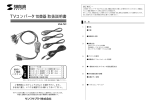
Checking LED
XB1-PC4main unit
SX4
(Left Down)
Connector for PWM servo
XBus supporting receivers
Power harness(Sold separatly)
XB1-CHB
(Sold separatly)
Lead harness(Sold separatly)
(Sold separatly)
RX Battery
(sold separately)
※This product converts the XBus signal to a PWM signal that then allows
the use of normal/PWM (non XBus) servos with JR s XBus system.
This product does not have an integrated regulator. Please check the rated
voltage of the target products and use the proper source battery for the
receiver.
Channel (ID) setting for each output connector must be performed by
either the Channel Programmer XB1-CPG or wirelessly from a JR
transmitter fitted with XBus.
Be sure the white connector of this product is connected to the XBus port
on the JR XBus receiver.
Power supply is not available from XBus connector.
Connect power supply to Deans Ultra Plug.
Use a power harness or a lead harness for cable extension.
Channel (ID) set up
The default factory initial set up for each connector (as supplied)
is as per the following.
SX1 : Throttle (1ch = ID1-1)
SX2 : Throttle (1ch = ID1-2)
SX3 : Throttle (1ch = ID1-3)
SX4 : Throttle (1ch = ID1-4)
Sub-IDs are different at all Throttle channels.
Channel (ID) setting/changing for each output connector must be
performed by either the Channel Programmer XB1-CPG or wirelessly from
a JR transmitter fitted with XBus (like XG14). If the IDs are wrongly set up,
please set up again by using the XB1-CPG or a JR transmitter fitted with
XBus (like XG14).
During set up ID with XG1-CPG, connect a RX battery to Deans Ultra Plug.
※Please note that only JR XBus compatible transmitters can
be used with this item.
Sub-ID
Up to 4 Sub-ID can be set for each channel.
By giving independent Sub-IDs, individual setting can be carried
out even for the servos connected to the same channel.
Operation check and confirmation
Connect the connector(white) to the XBus port on a JR XBus
receiver or directly to a XBus Hub, and the
connector(s)(black) to PWM servo(s). Upon receipt of proper
signal from XBus, the checking LED will light and signal
output starts. Make sure the servo(s) can be operated
properly on the setting channel (ID) that you require.