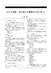
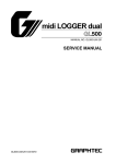
1
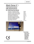
GL400 GL400 GL400 Series GL400 Series Series Series Spectra Precision Division Trimble Trimble Construction Trimble Trimble Construction Construction Construction Division Division Division Division 8261 Kellenburger State 235 5475 5475Route 5475 Kellenburger 5475Kellenburger Kellenburger Road RoadRoad Road Ohio 45424 Dayton,Dayton, Dayton, Dayton, Ohio Ohio 45424 Ohio45424 45424 USA USA U.S.A. USA USA User Guide User Guide User User Guide Guide Bedienungsanleitung Bedienungsanleitung Bedienungsanleitung Bedienungsanleitung Manuel Manuel de l´utilisateur Manuel Manuel de l´utilisateur dede l´utilisateur l´utilisateur Guida per Guida l´uso Guida per Guida l´uso per per l´uso l´uso Gúia delGúia usuario del Gúia Gúia usuario deldel usuario usuario Gebruikershandleiding Gebruikershandleiding Gebruikershandleiding Gebruikershandleiding Operatörshandbok Operatörshandbok Operatörshandbok Operatörshandbok Brugermanual Brugermanual Brugermanual Brugermanual Guia do Guia Usuário do Guia Guia Usuário dodo Usuário Usuário Bruksanvisning Bruksanvisning Bruksanvisning Bruksanvisning Käyttäjän Käyttäjän opasKäyttäjän Käyttäjän opas opas opas Руководство пользователя 取扱説明書 取扱説明書 取扱説明書 取扱説明書 +1-937-245-5600 +1-937-245-5600 +1-937-245-5600 +1-937-245-5600 Phone Phone +1-937-245-5010 Phone Phone © 2007, Trimble ©Navigation 2007, Trimble © 2007, Limited. © Navigation 2007, Trimble All Trimble rights Navigation Limited. Navigation reserved. AllLimited. rights Limited. reserved. All rights All rights reserved. reserved. www.trimble.com www.trimble.com www.trimble.com www.trimble.com www.trimble.com www.trimble.com www.trimble.com www.trimble.com PN Q103506 Rev. G (01/13) 130055_00_GL400_Umschlag.indd 1 15.01.13 14:36 8 8 6 6 5 5 4 4 7 7 15 15 17 17 2 2 1 1 3 3 16 16 17 17 11 11 12 12 7 7 2 2 10 10 9 9 6 6 3 3 1 1 13 13 14 14 Printed in Germany 130055_00_GL400_Umschlag.indd 2 Q103506 Rev. G (01/13) 15.01.13 14:36 TABLE OF CONTENTS FOR YOUR SAFETY COMPONENTS How to Use the Laser System Powering the Laser Laser Setup Turning On/Off the Laser Turning On/Off the Radio Remote Control Matching the Remote Control with the Transmitter Activating/Deactivating Standby Mode Using the Manual Mode Mask Mode Y(/)- or X(y)-Axis Slope Mode Grade Match Mode (GL422 only) APPLICATIONS General Construction Determining the Height of Instrument (HI) Using the Slope Mode Establishing Vertical Alignment CALIBRATION Checking Calibration of the Y- and X-Axes Checking Calibration of the Z-(vertical) Axis PROTECTING THE UNIT CLEANING AND MAINTENANCE PROTECTING THE ENVIRONMENT WARRANTY TECHNICAL DATA GB 5 6 6 6 7 7 8 8 8 9 9 9 10 11 11 11 11 11 12 12 12 12 12 13 13 13 Introduction Thank you for choosing one of the Spectra Precision Lasers from the Trimble family of precision grade lasers. The grade laser is an easy-to-use tool that offers accurate horizontal, vertical and sloped laser reference up to 1300 ft (400 m) away using a receiver. FOR YOUR SAFETY For hazardless and safe operation, read all the user guide instructions. • Use of this product by people other than those trained on this product may result in exposure to hazardous laser light. • Do not remove warning labels from the unit. • The GL422 is Class 3A/3R (< 5mW, 600 ... 680 nm). The GL412 laser is subject to Class 2 (< 3.4 mW, 600 ... 680 nm). • Never look into the laser beam or direct it to the eyes of other people. • Always operate the unit in a way that prevents the beam from getting into people‘s eyes. If initial service is required, which results in the removal of the outer protective cover, removal must only be performed by factory-trained personnel. Caution: Use of other than the described user and calibration tools or other procedures may result in exposure to hazardous laser light. Caution: Unsafe operation may result if the product is used differently than described in this operator‘s manual. 5 120686_01_GL400_GB.indd 5 30.05.12 10:27 COMPONENTS 1 2 3 4 5 6 7 8 9 10 11 12 13 14 15 16 17 Power Button Battery LED Manual/Standby Button Leveling LED Manual/HI-Warning LED Up and Down Arrow Buttons Left and Right arrow Buttons Liquid Crystal Display (LCD) Rotor Sunshade Sighting Guides Axes-Alignment-Marks Recharge Jack Handle Battery door 5/8x 11 Tripod Mounts Rubber feet How to Use the Laser System Powering the Laser Batteries WARNING Ni-MH batteries may contain small amounts of harmful substances. Be sure to charge the battery before using it for the first time, and after not using it for an extended length of time. Charge only with specified chargers according to device manufacturer‘s instructions. Do not open the battery, dispose of in fire or short circuit; it may ignite, explode, leak or get hot causing personal injury. Dispose in accordance with all applicable federal, state, and local regulations. Keep the battery away from children. If swallowed, do not induce vomiting. Seek medical attention immediately. Installing Batteries Remove the battery door by turning the center knob 90° counterclockwise. Insert batteries (or a rechargeable battery pack) into the housing so that the negative poles are on the bigger battery spiral springs. DO NOT REMOVE RECHARGEABLE BATTERIES FROM THEIR HOLDER AND INSTALL ALKALINE BATTERIES, SEVERE DAMAGE TO UNIT WILL RESULT IF CHARGING IS ATTEMPTED. Install the battery door and tighten it by turning the center screw 90° clockwise. A mechanical switch prevents alkaline batteries from being charged. Only the original rechargeable battery pack allows charging within the unit. Any other rechargeable batteries have to be charged externally. Recharging the Batteries The laser is shipped with rechargeable NI-MH batteries. Note: The battery LED shows the approximate charge of the batteries. The LED will flash when battery voltage is between 3.8 and 4.0 volts. The LED will be on continuously when battery voltage is less than 3.8 volts. The charger requires approx. 10 hours to charge empty rechargeable batteries. For charging, connect the plug of the charger to the recharge jack of the unit. New or long-time out-of-use rechargeable batteries reach their best performance after being charged and recharged five times. The batteries should only be charged when the laser is between 50° F and 104° F (10° C to 40° C). Charging at a higher temperature may damage the batteries. Charging at a lower temperature may increase the charge time and decrease the charge capacity, resulting in loss of performance and shortened life expectancy. 6 120686_01_GL400_GB.indd 6 30.05.12 10:27 Laser Setup Position the laser horizontally (tripod mount and rubber feet downward!) on a stable platform, wall mount or tripod at the desired elevation. The laser recognizes automatically whether it is used horizontally or vertically when switched on. Turning On/Off the Laser Press the power button to turn on the laser. GL422 – Display GL412 – Display The LEDs (2, 4 and 5) are turned on for 2 seconds. At the LCD, the last used grade values, the mask mode status and the antenna symbol will be displayed. Note: The laser always powers up in the automatic self-leveling mode with 600 rpm and the lastentered grade. The laser is level when the leveling indicator 4 is no longer flashing (once every second) and the grade values at the laser’s and remote control’s LCD are not flashing. For the first five minutes after the laser self levels, the LED 4 lights solid then flashes every four seconds to let you know the laser is still level. Repeatedly pressing and releasing the up and right arrow buttons simultaneously toggles the rotation speed between 300 and 600 rpm (GL412/GL422), and 0 rpm (GL422). At 0 rpm (GL422), the beam stops on the opposite side of the keypad. With the left and right arrow buttons, the beam can be adjusted in line with the sighting guides for “Over the Top” pipe laying applications. Note: If the temperature changes after the laser has been turned on by more than 5 degrees C (10 degrees F) the laser will compensate for the temperature change by resetting the leveling system. During a temperature compensation reset, the grade display flashes, rotation stops and the laser beam turns off. When the temperature compensation reset has been finished, a new grade value can be dialed into the unit. If desired, an additional temperature compensation reference check can be initiated anytime by simultaneously pressing the right and down arrow buttons at the transmitter or the remote control. Note: When the laser is set up vertically and turned on, the rotor centers in its line range automatically. The LCD indicates line can be adjusted by using the up/down (/) buttons. If the laser is positioned beyond its self-leveling range of ±9%, the manual and leveling indicators flash simultaneously and a warning sound is emitted. Turn the unit off, reposition the laser within the self-leveling range and turn it on again. Note: If the laser is out of its self-leveling range and remains out of it for more than 10 minutes, it shuts down completely. HI alert: After the laser has been level for more than 5 minutes, the HI (height of instrument) alert activates. If the laser is disturbed (tripod bumped, etc.) so that when it re-levels the laser beam elevation changes by more than 3 mm (1/8 in.), the HI alert shuts down the laser and rotor, a warning sound occurs and the red LED flashes two times per second (twice the manual-mode rate). In a HI condition, a HI and flashing dashed lines appear at the laser’s and remote control’s LCD. To restore level, turn the laser off and on. After the laser has re-leveled, check your initial reference elevation. Note: The HI-alert condition can also be deleted by activating/deactivating the Standby mode with the remote control. In order to switch the laser off, press the power button again. 7 120686_01_GL400_GB.indd 7 30.05.12 10:27 Selecting different sensitivity modes Note: The unit has the capability to monitor and detect windy, high vibration or unstable setups, and automatically adjusts level sensitivity and other internal modes accordingly to allow work to continue in these conditions. A “Sensitive Mode” can also be selected for highly accurate sensitive applications. To set the laser to “Sensitive Mode”: 1. Turn on the laser 2. Quickly press and hold the up and left arrow buttons simultaneously at the transmitter to activate the sensitive mode. Note: A long beep occurs and an “S” is displayed at the right lower transmitter’s LCD display’s corner to confirm the laser is in “Sensitive Mode”. 3. To place the laser back to standard sensitivity mode, quickly press and hold the up and left arrow buttons simultaneously at the transmitter again. A short beep is heard and the “S” in the LCD is turned off to confirm the laser is back in standard mode Note: The unit always powers up with the last selected mode. Turning On/Off the Radio Remote Control The radio remote control is a hand-held device that allows you to send operational commands to the laser from a remote location. A “T” appears in the right corner of the laser’s and remote’s first display line indicating a connection between the laser and the remote control has been made. A flashing “T” indicates that the connection has been interrupted, e.g. the operating range has been exceeded. When the radio remote control and laser are communicating, a bar above the “T” (antenna icon) appears. Press the power button to turn on the radio remote control. Note: When the radio remote control is initially turned on, the standard display (model number and software version) appear for the first 3 seconds, then the axes symbols and last-entered grade for each axis briefly appear in the LCD. If the connection between the laser and remote is interrupted for more than 3 seconds, the standard display appears again until the connection is re-established. When the remote control is initially turned on and after every button press, the LCD backlight is activated and turns off automatically if no button is pressed for 8 seconds. The LED (2) indicates the remote control’s battery status (similar function as the battery LED at the laser). To turn off the radio remote control, press and release the power button. Note: 20 minutes after the last button press, the remote control turns off automatically. Matching the remote control with the transmitter In order to make sure the remote control can communicate with the transmitter, both units have to be matched. First, make sure the transmitter and the remote control are turned off. Then press and hold the right arrow button and turn on the transmitter. Next, repeat the same steps on the remote control. Both displays show the following information: After one second, the last used grade values, the mask mode and the antenna symbol are displayed at both displays to indicate the transmitter has been matched with the remote control. Activating/Deactivating Standby Mode 8 120686_01_GL400_GB.indd 8 30.05.12 10:27 Standby mode is a power-saving feature that conserves laser battery life. Press and hold the laser’s or remote control’s manual button for 3 seconds to activate standby mode. Note: When standby mode is activated, the laser beam, rotor, self-leveling system, and LEDs shut down, but the HI alert remains activated. To let you know that the laser is in standby mode, the battery LED flashes every 4 seconds and dashed lines appear in the laser’s and remote control’s LCD. To deactivate standby mode and restore full operation of the laser, press and hold the laser’s or remote control’s manual button for 3 seconds. The laser and all other functions turn on again. Using the Manual Mode Manual horizontal Manual vertical Pressing the manual button on the laser or the remote control changes the laser from automatic self-leveling mode to Manual mode. Manual mode is indicated by the flashing (once every second) red LED 5 plus scrolling horizontal segments appear in the LCD. In Manual mode (horizontal), the Y(/)-axis can be sloped by pressing the Up- and Down-Arrow-buttons on the laser‘s keypad or the remote control. Additionally, the X(y)-axis can be sloped by pressing the Left- and Right-Arrow-buttons on the laser or remote control. In vertical mode, the up and down arrow buttons align the laser beam to the right/left side, and the left and right arrow buttons adjust the slope of the laser beam. To resume automatic self-leveling mode, press the manual button again. Mask Mode Mask Mode – permits turning off the laser beam (electronic shutters) in up to 3 lighthouse windows. Mask Mode is used when multiple lasers are on the jobsite and they are interfering with each other’s receiver. Regardless of a horizontal or vertical setup, the mask mode for +/-Y- or +/-X-axis is selected by pressing the manual button in sequence with one of the arrow buttons. Pressing the up or down arrow button in sequence with the manual button will activate/deactivate the mask mode for the + or – Y axis. To activate the mask mode on the +Y-axis, press the up arrow button at the laser or remote control, then within <1 second press and release the Manual button. To activate the mask mode on the -Y-axis, follow the same sequence only start with the down arrow button. The right or left arrow button in sequence with the manual button will activate/deactivate the mask mode for the + or – X axis accordingly. To indicate which side of the laser the beam has been turned off, the bars on the same side of the mask mode symbol are turned off. Note: The unit always powers up with the mask mode deactivated (default). Y(/)- or X(y)-Axis Slope Mode Changing the Grade Value of the Y (/)- and X (y)-Axes Note: The laser automatically self-levels up to +/-9% grade from a leveled tripod. Tilt the laser towards the up-grade direction for larger grades to make sure the laser is inside its self-leveling range. The grade value for both axes can be changed using two methods – standard and quick-change. The standard method is used for entering small changes in the grade value. The quick-change method is used for setting grade to zero and entering large changes in the grade value. To activate the grade change mode, press and hold one of the arrow buttons; a single beep confirms the grade change mode has been entered. The single slope laser GL412 grade value can only be changed on the Y (/)-axis using the up and down arrow buttons. 9 120686_01_GL400_GB.indd 9 30.05.12 10:27 Standard Method Press and hold the up or down button for the Y (/)-axis and the left or right button for the X (y)-axis until the correct grade value appears in the laser’s and remote control’s LCD. Note: The speed of the grade value change increases with the amount of time the button is held down. Note: Grade values from 0 to +/-9.999% are displayed to 3 decimal places. Grade values greater than 10% are displayed to 2 decimal places. To reverse the sign of the Y (/)- or X (y)- grade, press and release the manual button quickly while in grade change mode. The laser will self-level to the required grade position 2 seconds after releasing the grade change arrow button or after pressing an arrow button of the unused axis; a single beep confirms the grade change mode has been left. Note: The grade values at the laser’s and remote control’s LCD will flash until the laser has been self-leveled to the requested grade position. Quick-Change Method Note: The grade value can be quickly set to 0.000% by simultaneously pressing and holding the arrow buttons for the axis you want to change 1. Simultaneously press and hold the up and down buttons for the Y-axis or the left and right buttons for the X-axis to set the grade value to 0.000%. 2. Continuing to press and hold the up and down / left and right buttons will change grade in 1% increments. Note: The grade value for both axes increases in 1.00% increments. When the grade value for either axis reaches its highest amount, the grade value switches to the lowest value for that axis. For example, the value switches from +15% to -10%. The laser will self-level to the required grade position, 2 seconds after releasing the grade change arrow button or after pressing an arrow button of the unused axis; a single beep confirms the unit left the grade entry mode. Note: The grade values at the laser’s and remote control’s LCD will flash until the laser has been self-leveled to the requested grade position. Grade Match Mode (GL422 only) In Grade Match mode, the laser can be used to measure the existing grade value between two known elevation points on the Y ( ) - axis. Press and release the manual button at the transmitter or remote control twice. Note: The manual and leveling LED will flash simultaneously. A “G” appears in the LCD’s right bottom corner and after 3 seconds both grade values are set to 0%. If the manual button is pressed again before the 3 seconds are up, the unit goes back to the previously used grade value. Grade Match activated Grade indication during Grade Match Change the beam slope by using the up and down arrow buttons at the transmitter or remote control until the receiver shows an on-grade. Note: During grade match, the Y- axis grade value changes by 2 decimal place resolution. To resume automatic self-leveling mode, press and release the manual button again. The LCD will show the measured final grade value on the Y( ) – axis to 3 decimal places. Note: After grade match has been completed, the X-axis can then be changed to any required grade value. 10 120686_01_GL400_GB.indd 10 30.05.12 10:27 APPLICATIONS General Construction Determining the Height of Instrument (HI) The height of instrument (HI) is the elevation of the laser’s beam. The HI is determined by adding the grade-rod reading to a benchmark or known elevation. 1. Set up the laser and place the grade rod on a job-site benchmark (BM) or known elevation. 2. Slide the receiver up/down the grade rod until it shows an on-grade reading. 3. Add the grade-rod reading to the benchmark to determine the height of instrument. Example: Benchmark = 30.55 m (100.23 ft) Rod reading = +1.32 m (+4.34 ft) Height of instrument = 31.87 m (104.57 ft) Use this HI as a reference for all other elevations. Height of Instrument (HI) Rod Reading 1.32 m (4.34 ft) HI Benchmark 30.55 m (100.23 ft) HI = Rod Reading + Benchmark HI = 1.32 m + 30.55 m = 31.87 m (4.34 ft + 100.23 ft = 104.57 ft) Using the Slope Mode 1. Set up the laser over the reference point (A). 2. Use the sighting guides on the top of the laser to align the laser to the desired direction hub. Turn the laser on the tripod until it is properly aligned. 3. Attach a receiver to a grade rod. Set the grade rod on the direction hub (B) with the grade value 0% on both axes to check the laser’s elevation. Note: Use this HI as a reference for checking the alignment of the laser after setting the slope. B C L A C 4. Dial in a slope for the cross (y) axis by pressing the laser’s or remote control’s left or right arrow button. 5. Recheck the laser’s elevation using the HI in step 3 on the 0% axis at point (B). Note: If the HI has been changed, rotate the laser on the tripod until you get an on-grade reading again. Make sure you DON’T change the height of the receiver on the grade rod. 6. Dial in the final required grade value on one or both axes. Note: Axis alignment over a short distance can be done by using only the sighting guides on the sunshade which allows the user to skip points 3 to 5. Note: After you’ve finished grading on one side of the road, you can reverse the sign of the y axis using the radio remote control. To reverse the sign of the Y (/)- or X (y)- grade, press and release the manual button quickly while in grade change mode. Establishing Vertical Alignment 1. Set up the laser on its side over the first reference point. 2. Position the receiver at the second reference point. 3. To adjust the laser beam for line direction, use the up and down buttons on the laser or radio remote control until the laser beam matches the line point. Note: To adjust the vertical laser beam different to the plumb position, press and release the manual button and then use the left and right buttons on the laser or the radio remote control. 11 120686_01_GL400_GB.indd 11 30.05.12 10:27 CALIBRATION Checking Calibration of the Y- and X-Axes 1. Set up the laser 30 m (100 ft) from a wall and allow it to level. 2. Set the grade to 0.000% in both axes. 3. Raise/lower the receiver until you get an on-grade reading for the +Y axis. Using the on-grade marking notch as a reference, make a mark on the wall. Y+ Y1 Note: For increased precision, use the fine-sensitivity setting (1.5 mm/ 1/16 in.) on the receiver. 30 m (100 ft) 4. Rotate the laser 180° (-Y axis toward the wall) and allow the laser to re-level. 5. Raise/lower the receiver until you get an on-grade reading for the –Y/axis. Using the on-grade marking notch as a reference, make a mark on the wall. 6. Measure the difference between the two marks. If they differ more than 3 mm at 30 m (1/8 inch at 100 feet), the laser needs calibrating. -Y Y2 30 m (100 ft) 7. After checking the Y-axis, rotate the laser 90°. Repeat the above starting with the + X axis facing the wall. x+ 30 m (100 ft) Checking Calibration of the Z-(vertical) Axis To check vertical calibration, you need a plumb bob with at least 10m (30ft) of string. 1. Suspend the plumb bob in front of a house i.e., attached to a window frame whose window height is at least 10m (30ft). 2. Set up the laser in vertical so that the laser beam strikes the receiver’s on-grade position at the top of the string. 3. Look for any deviation using the receiver from the top of the string to the bottom of it. If the deviation is more than 1mm (<1/16 in.), the vertical axis needs calibrating. Note: If calibration is required, please, refer to the calibration instructions on our Trimble website www.trimble.com/support.shtml. PROTECTING THE UNIT Do not expose the unit to extreme temperatures or temperature changes (do not leave inside the car). The unit is very robust and can resist damage if dropped even from tripod height. Before continuing your work, always check the leveling accuracy. See Checking Calibration section. The laser is water proof and can be used indoors and outdoors. CLEANING AND MAINTENANCE Dirt and water on the glass parts of laser or prism will influence beam quality and operating range considerably. Clean with cotton swabs. Remove dirt on the housing with a lint-free, warm, wet and smooth cloth. Do not use harsh cleansers or solvents. Allow the unit to air dry after cleaning it. 12 120686_01_GL400_GB.indd 12 30.05.12 10:27 PROTECTING THE ENVIRONMENT The unit, accessories and packaging ought to be recycled. This manual is made of non-chlorine recycling paper. All plastic parts are marked for recycling according to material type. Do not throw used batteries into the garbage, water or fire. Remove them in compliance with environmental requirements. Notice to Our European Union Customers For product recycling instructions and more information, please go to: www.trimble.com/environment/summary.html Recycling in Europe: To recycle Trimble WEEE, Call +31 497 53 2430, and ask for the “WEEE Associate” Or Mail a request for recycling instructions to: Trimble Europe BV c/o Menlo Worldwide Logistics Meerheide 45 5521 DZ Eersel, NL WARRANTY Trimble warrants the GL400 to be free of defects in material and workmanship for a period of 5 years. Trimble or its authorized service center will repair or replace, at its option, any defective part, or the entire product, for which notice has been given during the warranty period. If required, travel and per diem expenses to and from the place where repairs are made will be charged to the customer at the prevailing rates. Customers should send the product to Trimble Navigation Ltd. or the nearest authorized service center for warranty repairs or exchange, freight prepaid. Any evidence of negligent, abnormal use, accident, or any attempt to repair the product by other than factory-authorized personnel using Trimble certified or recommended parts, automatically voids the warranty. The foregoing states the entire liability of Trimble regarding the purchase and use of its equipment. Trimble will not be held responsible for any consequential loss or damage of any kind. This warranty is in lieu of all other warranties, except as set forth above, including any implied warranty merchantability of fitness for a particular purpose, are hereby disclaimed. This warranty is in lieu of all other warranties, expressed or implied. TECHNICAL DATA Laser Leveling accuracy1,3: Grade accuracy 1,3: Rotation: Operational area GL422 1,2: Operational area GL412 1,2: Laser type: Laser class GL422 /GL412: Self-leveling range: Grade range GL422: Grade range GL412: Leveling indicators: Laser beam diameter1: Operating range using remote control: Power source: Battery life1: Operating temp.: Storage temp.: Tripod attachments: ± 0.5 mm/10 m, 1/16“ @ 100 ft, 10 arc seconds ± 1.0 mm/10 m, 1/8“ @ 100 ft, 20 arc seconds at grades from -2.5 to +2.5%, ± 3.0 mm/10m (3/8” @ 100 ft), 60 arc seconds at grades over +/- 2.5%. 600 (300) rpm (GL412/422); 0 rpm (GL422) appr. 400 m (1300 feet) radius with detector appr. 300 m (1000 feet) radius with detector red diode laser 635 nm – GL422; 650 nm – GL412 Class 3A/3R, <5mW / Class 2, <3.4mW; t <0.25 sec appr. ± 5° -10% to +15% both axes (not simultaneously) -10% to +15% Y(/)-axis LED flashes appr. 8 mm up to 100 m (330 ft) 4 x 1.5V D - cell (LR20) 28 hrs NiMH; 90 alkaline -20°C to 50°C (-4°F to 122°F) -20°C to 70°C (-4°F to 158°F) 5/8 x 11 horizontally and vertically 13 120686_01_GL400_GB.indd 13 30.05.12 10:27 Dust and Water proof Weight: Low voltage indication: Low voltage disconnection: IP66 3.1 kg (6.8 lbs) flashing/shining of the battery indicator unit shuts off 1) at 21° Celsius 2) under optimal atmospheric circumstances 3) along the axis Remote control Operating range: Power source: Battery life 1: Dust and Water proof Weight: up to 100 m (330 ft) 2 x 1.5V AA alkaline batteries 130 hours IP54 0.18 kg (0.4 lbs) DECLARATION OF CONFORMITY Please disregard the declaration of conformity within the manual. Following is the valid declaration: We Trimble Kaiserslautern GmbH Declare under our sole responsibility that the products GL412/422 and RC402 To which this declaration relates is in conformity with the following standards: EN300 440-2 V1.1.1:2004, EN301 489-03 V1.4.1:2002, EN301 489-01 V1.4.1:2002, EN50371:2002, IEC 60825-1:2007 following the provisions of directive R&TTE 1999/5/EC The managing director Electro-Magnetic Compatibility Declaration of Conformity This digital apparatus does not exceed the Class B Limits for radio noise for digital apparatus set out in the Radio Interference Regulations of the Canadian Department of Communications. This device complies with part 15 off the FCC rules. Operation is subject to the condition that this device does not cause harmful interference. Note: The product been tested and found to comply with the limits for a Class B digital device, pursuant to part 15 of the FCC rules. These limits are designed to provide reasonable protection against harmful interference in a residential installation. The product generates, uses and can radiate radio frequency energy and, if not installed and used in accordance with the instructions, may cause harmful interference to radio or television reception, which can be determined by turning the product off and on. The user is encouraged to try to eliminate the interference by one or more of the following measures: • Reorient or relocate the receiving antenna. • Increase the separation between the product and the receiver. • For more information, consult your dealer or an experienced radio/television technician. Caution: Changes or modifications to the product that are not expressly approved by Trimble could void authority to use the equipment. 14 120686_01_GL400_GB.indd 14 30.05.12 10:27 整準感度の選択 メモ:強い風や振動等の不安定な状況下で、 レーザ光の大きなゆれによる作業への影響を最小限にし たい場合は、 「センシティブ・モード」を選択します。 センシティブ・モードの設定 1.発光機をオンにします。 2.起動時に、本体の上と左の矢印ボタンを同時に押し続けると、センシティブ・モードで立ち上がります。 メモ:長いピーッという音と液晶画面の右下に「S」が表示されれば、センシティブ・モードの状態です。 3.通常の状態に戻すには、 もう一度本体の上と左の矢印ボタンを同時に押し続けます。短いピッという音と液晶画 面の「S」表示が消えて、通常の状態に戻ります。 メモ:本機を起動する際は、直前に選択されたモードで立ち上がります。 無線リモートコントロールをオン・オフする 無線リモートコントロールは、遠隔地から発光機へ操作コマンドを送信することができる携帯用機器です。発光機 とリモートコントロールが接続すると、発光機とリモートコントロールの初期画面の右端に 「T」の文字が表示されま す。 「T」が点滅しているときは、接続が遮断されていることを表します (例:通信可能な範囲を外れた場合など) 。無線 リモートコントロールと発光機が通信しているときは、 「T」 (アンテナのアイコン)の上に横棒が表示されます。 電源ボタンを押して無線リモートコントロールを起動します。 メモ: 無線リモートコントロールを起動すると、 まず始めに標準画面(モデル番号とソフトウェア・バー ジョン)が3秒間表示され、その後に軸のシンボルと各軸に最後に入力された勾配が短い間表示され ます。発光機とリモートコントロールの接続が3秒以上遮断されると接続が再度確立されるまでの間 標準画面が表示されます。 リモートコントロールの起動時とボタン操作を行った後には液晶画面のバックライトが点灯しますが、その後8秒 以上何のボタン操作も行われなければ自動的に消灯します。 LED (2) はリモートコントロールのバッテリの状態を示します(レーザのバッテリLED と同様の機能です)。 無線リモートコントロールを終了するには、電源ボタンを押してください。 メモ: 20 分以上何もボタン操作が行われませんとリモートコントロールは自動的に電源をOFFしま す。 発光機とリモートコントロールを同期させる リモートコントロールが発光機と通信できるようにするには両機を同期させる必要があります。 まず、発光機とリモ ートコントロールの電源を切っておきます。 そして発光機の右矢印のボタンをしばらく押し続け、発光機を起動しま す。次に同じ操作をリモートコンロトールにも行います。両方の機器の画面には下記の情報が表示されます。 1秒後に両機の画面に最後に使用された勾配と、マスクモードとアンテナのシンボルが表示されたら、発光機とリ モートコントロールが同期されたことを意味します。 スタンバイモード 8 124 130055_13_GL400_JAP.indd 124 8 Q103506_RevC_GL4X2_JP_0908.indd 12:42 17/10/200818.01.13 3:28:51 p.m. Q103 p.m. スタンバイモードは、バッテリ電力を節約するためのモードです。 本体またはリモートコントロールのマニュアルボタンを3秒押し続けると、スタンバイモードに切り替わります。 メモ: スタンバイモードのとき、レーザ光とロータ、自動整準システム、LEDは停止しますが、機械高警 告はオンのままです。 発光機がスタンバイモードであることを示すために、バッテリLEDは4秒に1回点滅し、発光機とリモー トコントロールの液晶画面に破線が表示されます。 スタンバイモードをオフにして、発光機の全機能を使用できるようにするには、本体またはリモートコントロールの マニュアルボタンを3秒間押し続けます。本体とその他すべての機能が再び使用可能になります。 マニュアルモード マニュアル水平 マニュアル垂直 本体またはリモートコントロールのマニュアルボタンを押すと、自動整準モードからマニュアルモードに切り替わ ります。マニュアルモードになると、赤いLED(5)が毎秒点滅するようになり、さらに水平スクロールセグメントが 液晶画面に現れます。 マニュアルモード(水平)では、Y(∠) 軸の勾配設定は発光機のキーパッドまたはリモートコントロールの上・下矢印 ボタンを押すことで調整できます。同様にX(y)軸の勾配入力は本体のキーパッドまたはリモートコントロールの 左・右矢印ボタンを押すことで調整できます。 垂直モードでは、上・下矢印ボタンを押すとレーザ光が左・右に移動します。左・右矢印ボタンはレーザ光の傾き を調整します。 自動整準モードに戻るには、もう一度マニュアルボタンを押します。 マスクモード マスクモード – レーザ光の出射口を3つまで塞ぐことができ (電子シャッターにより)、現場に複数の発光機があっ て互いの受光器に干渉しているときに使用します。 水平、垂直の設置に関わらず、マスクモードでは矢印ボタンの1つに続いてマニュアルボタンを押し、+か-Y軸ま たは+か-X軸を選択します。マニュアルボタンに続けて上または下の矢印ボタンを押すと、Y軸の+または-の マスクモードが作動、 または終了します。+Y軸にマスクモードを作動させるには、発光機かリモートコントロールの 上の矢印ボタンを押し、1秒以内にマニュアルボタンを押します。Y軸にマスクモードを作動させるには最初に下の 矢印ボタンを押し、後は同じ手順で行います。 同様に、右か左の矢印ボタンをマニュアルボタンに続けて押すと+ または – X 軸のマスクモードを作動または終 了させることができます。 マスクモードが作動すると、 シンボルの同じ位置にある棒が消え、その出射口が塞がれていることを示します。 メモ: マスクモードが終了すると、機器の出力があがります(標準設定)。 Y軸 (∠) またはX軸 (y) の勾配設定方法 Y軸 (∠) とX軸 (y) の勾配を変える メモ: レーザは水平に設置された三脚の上で0%~±9%までの勾配を自動的に整準します。 より大きい勾配に対しては発光機を上向きに傾け、発光機が自動整準範囲内にあるようにしてください。 両方の軸に対する勾配は標準、 またはクイック・チェンジのいずれかの方法で変えられます。標準の方法は勾配 を小さく変更する場合に使用されます。 クイック・チェンジは勾配をゼロに設定し、それから大きく変更する場合 に使用します。 勾配変更モードを作動させるには、矢印ボタンのうちの1つをしばらく押し続けます。勾配変更モードになるとピ ッという音が1回鳴ります。1方向勾配レーザ GL412 の精度は、上下の矢印ボタンを使用してY (∠)軸のみ変更 することができます。 1259 130055_13_GL400_JAP.indd 125 9 Q103506_RevC_GL4X2_JP_0908.indd 12:42 17/10/200818.01.13 3:28:52 p.m. 標準的な方法 Y (∠) 軸の上下の矢印ボタンとX (y) 軸の左右ボタンを、発光機とリモートコントロールの液晶画面に正しい勾 配が表示されるまで押し続けます。 メモ: 勾配の変化する速さはボタンを押し続ける時間によって変わります。 メモ: 0 から ±9.999% までの勾配が1000分の1パーセント単位で表示されます 10% 以上の勾配は100分の1パーセントで表示されます。 Y (∠) または X (y) 勾配の数値を戻すには、勾配変更モードのときにマニュアルボタンを押します。 発光機は、勾配変更の矢印ボタンを離してから2秒後、 または使用していない軸の矢印ボタンを押してから2秒後 に指定された勾配位置に自動整準します。勾配変更モードが終了するとピッという音が1回鳴ります。 メモ: 発光機とリモートコントロールの液晶画面の勾配は、発光機が指定された勾配位置に自動整準 するまで点滅します。 クイックチェンジ メモ: 変更したい軸の矢印ボタンを同時に押し続けると勾配を素早く0.000% に変更することができ ます。 1. Y軸の上下ボタンまたはX軸の左右ボタンを同時に押し続けて勾配を0.000%に設定します。 2. 上下ボタンまたは左右ボタンを押し続けると勾配が1% ずつ増加します。 メモ: 両方の軸の勾配は1.00% ずつ増加します。最も高い値に達すると、次に最も低い値になります。 つまり+15% の次は -10%になります。 発光機は、勾配変更の矢印ボタンを離してから2秒後、 または使用していない軸の矢印ボタンを押してから2秒後 に指定された勾配位置に自動整準します。勾配変更モードが終了するとピッという音が1回鳴ります。 メモ: 発光機とリモートコントロールの液晶画面の勾配は、発光機が指定された勾配位置に自動整準 するまで点滅します。 グレードマッチ・モード (GL422のみ) グレードマッチ・モードでは、Y(∠) 軸上の2点間の指定高さの勾配値を計測することができます。本体またはリモ ートコントロールのマニュアルボタンを2回押します メモ:マニュアルLEDと整準LEDが同時に点滅します。 液晶画面の右下に「G」が表示され、3秒後に両軸の勾配値は0%に設定されます。 3秒経過する前に再度マニュアルボタンを押すと、直前に使用されていた勾配値に戻ります グレードマッチ・モード始動 グレードマッチ・モードでの勾配値表示 グレードマッチ・モードに入ると両軸の勾配値を0%に 整準し直しますので、その間レーザ光は停止されます。 整準完了時、第1地点の設定高さにレーザ高を合わせます。あるいは、 グレードマッチ・モードに入る前にレーザ を0%にして第1地点に設置し、そのレーザ高を第1地点の指定高さに設定しておきます。 第1地点の高さ合せが終わったら次に第2地点の指定高さに受光器を設置し、オングレードを示すまで、本体ま たはリモートコントロールの上・下矢印ボタンを押してレーザ光の勾配を変更します。 メモ:グレードマッチ・モードでは、Y軸の勾配値は100分の1パーセント単位でカウントします。 自動整準モードに戻るには、 もう一度マニュアルボタンを押します。液晶画面は、計測されたY(∠)軸の 勾配値を1000分の1パーセントまで表示します。 メモ:グレードマッチを終了したら、X軸の勾配値は自由に設定できます。 10 126 130055_13_GL400_JAP.indd 126 10 Q103506_RevC_GL4X2_JP_0908.indd 12:42 17/10/200818.01.13 3:28:52 p.m. Q103 p.m. 使用推奨場所 一般土木 機械高の設定 機械高とは本体のレーザ光の高さです。 機械高は、ベンチマークまたは既知標高点の高さと、 標尺の値を足し算することで得られます。 1. 本体をセットアップして、標尺を現場のベンチマ ークまたは既知標高点の上に置きます。 2. 水平位置表示を示すまで、標尺上で受光器を上 下させます。 3. ベンチマークに標尺の値を加えて、機械高を求め ます。 例: ベンチマーク =30.55 m 標尺の値 =+1.32 m 機械高 =31.87 m この機械高をその他すべての高さの基準として使 用します。 Height of Instrument (HI) Rod Reading 1.32 m (4.34 ft) HI Benchmark 30.55 m (100.23 ft) HI = Rod Reading + Benchmark HI = 1.32 m + 30.55 m = 31.87 m (4.34 ft + 100.23 ft = 104.57 ft) 勾配の設定 1. 本体を基準点(A) の上に設定します。 2. 本体上部の視準ガイドを使用して、自動整準モードで使用される軸上にある方向杭と直線になる向きに本体 をあわせます。三脚上でレーザの向きを変え、一直線上になるように あわせます。 3. 受光器を標尺に取り付けます。本体の高さを確認するために、勾配0% の軸上の方向杭点(B)に標尺を設置します。 B メモ: 勾配を設定した後、この高さを基準高として勾配面の 確認に使えます。 4. 発光機かリモートコントロールの左または右矢印ボタンを押してクロ ス(y)軸用の勾配を入力します 5. (B) 点の 0%の軸上で手順3の機械高を使用してレーザ高を確認しま す。 CL A C メモ: 機械高を変更した場合は三脚の上で発光機の向きを変 え、 オングレードの高さになるように調整します。 標尺上の受光 器の高さは絶対に変更しないでください。 6. 片方の軸かまたは両方の軸に最終的に指定された勾配を入力します。 メモ: 短い距離での軸あわせは日よけの視準ガイドだけを使用して行うことができ、手順の3から5を 省略することができます。 メモ: 道路の片側の勾配を設定した後に、 リモートコントロールを使用してy 軸のサインを逆向きに することができます。 Y (∠) または X (y) 勾配のサインを逆にするには、勾配変更モードのときにマニュアルボタンを押します。 通り出し基準の設定 1. 最初の基準点上の手前側に発光機を設置します。 2. 受光器を2番目の基準点上に設置します。 3. レーザ光を線の方向に調整するには、 レーザ光が線のポイントに一致するまで発光機またはリモートコントロ ールの上下ボタンを押します。 メモ: 垂直レーザ光を下げ振り位置と異なる調整をするには、発光機またはリモートコントロールのマ ニュアルボタンを押し、左右ボタンを使用します。 11 127 130055_13_GL400_JAP.indd 127 11 Q103506_RevC_GL4X2_JP_0908.indd 12:42 17/10/200818.01.13 3:28:52 p.m. 精度の確認 Y軸とX軸の精度を確認 1. 壁から30 m離れた場所に+Y軸を壁に向けて発光機を設置し、本体 を整準させます。 2. 両方の軸を 0.000% に設定します。 3. +Y軸に対して水平位置表示を得るまで、受光器を上下に動かしま す。オングレードの位置でマークします。 Y+ Y1 メモ: 高精度を得るには、受光器をファインモード設定(1.5 mm)で使用します。 30 m (100 ft) 4. 発光機を180度回転して (-Y軸を壁に向ける) 、本体を整準させま す。. -Y 5. -Y軸に対して水平位置表示を得るまで、受光器を上下に動かしま す。 オングレードの位置でマークします。オングレード・マーキング ノッチを使用して壁にマークをつけます。 6. 2つのマークの差を測定します。その差が30 m当たり3 mm以上の 場合、調整が必要です。 7. Y軸の試験が終了したら、本体を90度回転します。上記の手順を、壁 に向いている+X軸から繰り返します。 Y2 30 m (100 ft) x+ 30 m (100 ft) Z(垂直)軸の精度を確認 垂直精度を確認するには、長さが最低10mの下げ振りが必要です 1. 家の前に下げ振りをぶら下げます(例:高さ10m以上の窓枠などにつける)。 2. 発光機を垂直に設置し、 レーザ光が糸上端で受光器のオングレード位置に照射されるようにします。 3. 糸の上端から下端までの間で逸脱がないか受光器を使って調べます。 1mm を超える逸脱があった場合は、垂直軸は精度の確認が必要です。 メモ: 精度の調整が必要な場合、ご購入先または弊社の営業所までご連絡ください。 管理 発光機を極度な高温や低温中に置いたり、極端な温度変化にさらさないでください。(車中に放置しないでくださ い。)本体は非常に堅牢で、三脚が転倒しても損傷を受けにくい構造になっています。しかし転倒後には、作業継続 前に整準精度を確認してください。精度の確認の項を参照してください。 本発光機は防水構造です。室内・屋外のどちらでも使用できます。 手入れ 発光機本体やプリズムのガラス部分が埃や水で汚れていると、レーザ光の質や測定範囲に大きな影響を与えま す。綿棒で汚れをふき取ってください。 その他の部分の汚れは、柔らかく、糸くずが出ない、濡れた温かい布で拭き取ってください。強力なクレンザーや 洗剤は使用しないでください。 汚れを拭き取った後は本体を自然乾燥させてください。 12 128 130055_13_GL400_JAP.indd 128 12 Q103506_RevC_GL4X2_JP_0908.indd 12:42 17/10/200818.01.13 3:28:54 p.m. Q103 p.m. 環境保護 発光機やアクセサリ、梱包材はリサイクルしてください。 この説明書は、無塩素再生紙です。 プラスチック部分はすべて、材質に応じてリサイクル用のマークが付いています。 使用済みの電池をごみや水、火の中に捨てないでください。環境規定に従って処理してください。 保証 法規制により、本体の部品及び製造に欠陥がないことを12ヶ月間保証します。幣社は本製品の故障に起因する付随 的損害については補償しかねます。操作を開始する前に必ず本書の「精度の確認」の章に従って精度をチェックし てください。修理しようとした形跡がある製品、あるいはラベルが無い製品は保証の対象外となります。 仕様詳細 発光機 整準精度1,3: 勾配精度y 1,3: レーザ光回転速度: 測定範囲 GL422 1,2: 測定範囲 GL412 1,2: レーザタイプ: レーザクラス GL422 /GL412: 自動整準範囲: 勾配範囲 GL422: 勾配範囲 GL412: 整準インジケータ: レーザ光の直径1: 遠隔操作時の作動範囲l: 電源: バッテリの動作時間1: 操作温度.: 保管温度: 三脚取付け: 埃と水への耐性: 質量: バッテリ残量警告: バッテリ切れ時: ± 0.5 mm/10 m、±10 秒 ±1.0 mm/10 m、±20 秒(-2.5 から+2.5%の勾配) ±3.0 mm/10m、±60秒(-2.5%以下または+2.5%以上の 勾配) 600 (300) rpm (GL412/422); 0 rpm (GL422) 半径約 400 m 【通常(視程10km)時】 半径約 300 m 【通常(視程10km)時】 赤色ダイオードレーザ 635 nm (GL422) 、 650 nm (GL412) クラス 3R, <5mW / クラス 2, <3.4mW; t <0.25 sec (IEC/EN60825-1:2001) 約±5度 -10% から+15% 両軸 (同時ではなく) -10% から+15% Y(∠)軸 LED 点滅 約 8 mm 最大100 m 単一型乾電池4本(LR20) ニッケル水素バッテリで28時間、アルカリ乾電池で90 時間 -20°C~ 50°C (-4°F~ 122°F) -20°C~ 70°C (-4°F~ 158°F) W5/8 水平・垂直 IP66 3.1 kg (6.8 lbs) バッテリインジケータが点滅・点灯 本体をオフにする 1) 気温が21℃の時 2) 最適な大気環境下において 3) 軸に沿って 129 13 130055_13_GL400_JAP.indd 129 Q103506_RevC_GL4X2_JP_0908.indd 13 18.01.13 12:42 17/10/2008 3:28:54 p.m. リモートコントロール 操作範囲: 電源: バッテリの動作時間 1: 埃と水への耐性: 質量: 最大100 m 単三型アルカリ乾電池2本 130 時間 IP54 0.18 kg 適合宣言 弊社 Trimble Kaiserslautern GmbH は、単独の責任において、この宣言が対象とする製品 GL422/412が Electromagnetic Compatibility (電磁適合性) 89/336/EEC 指令の条項に従って EN 61000-4-2, 1994、EN55022, 1994、EN 61000-4-3, 1997, IIEC 60825-1:2007 の基準に適合することを宣言します。 常務取締役 14 130 130055_13_GL400_JAP.indd 130 14 Q103506_RevC_GL4X2_JP_0908.indd 12:42 17/10/200818.01.13 3:28:54 p.m. Service and Customer Advice North & Latin America Trimble Spectra Precision Division 8261 State Route 235 Dayton, Ohio 45424 U.S.A. +1 (888) 272-2433 (Toll Free in U.S.A.) +1-937-482-0030 Fax www.trimble.com www.spectraprecision.com www.spectra-productivity.com Africa & Middle East Trimble Export Middle-East P.O. Box 17760 JAFZ View, Dubai UAE +971-4-881-3005 Phone +971-4-881-3007 Fax Europe Trimble Kaiserslautern GmbH Am Sportplatz 5 67661 Kaiserslautern GERMANY +49-6301-711414 Phone +49-6301-32213 Fax Asia-Pacific Trimble Navigation Singapore PTE Ltd. 80 Marine Parade Road, #22-06 Parkway Parade Singapore, 449269 +65 6348 2212 Phone +65 6348 2232 Fax China Trimble Beijing Room 2805-07, Tengda Plaza, No. 168 Xiwai Street Haidian District Beijing, China 100044 +86 10 8857 7575 Phone +86 10 8857 7161 Fax www.trimble.com.cn 120686_14_Customer.indd 131 31.07.12 06:34 120686_14_Customer.indd 132 30.05.12 11:15