Transcript
・ フォト
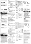
・マイクロセンサをねじ締め付けで固定する場合はM3ねじを
使用してください(ネジの緩み防止のためバネ座金を合わせて使
用してください)。
そのときの締めつけ強度は0.59N・m以下にして
ください。
■外形寸法
形EE-SPX301
形EE-SPX401
形EE-SPY301
形EE-SPY401
●電源について
形
EE-SPX301/401
EE-SPY30/40
アンプ内臓フォト・マイクロセンサ
取扱説明書 このたびは、本製品をお買い上げいただきまして、
まことにありがとうございます。
ご使用に際しては、次の内容をお守りください。
・電気の知識を有する専門家がお取り扱いください。
・この取扱説明書をよくお読みになり、
十分にご理解のうえ、正しくご使用ください。
・この取扱説明書はいつでも参照できるよう大切に保管してください。
スイッチングノイ
・ 市販のスイッチングレギュレーターを使用する際は、
ズにより誤動作することがあります。
フレームグランド端子およびグランド端子を接地して使用してくださ
い。
警告
+
○
OUT
−
○
安全を確保する目的で直接的または間接的に人体を検出す
る用途に本製品は使用できません。
人体保護用の検出装置として本製品を使用しないでください。
安全上の要点
・電源電圧について
仕様電圧範囲を超えて使用しないでください。仕様電圧範囲以上
の電圧を印加したり、交流電源を印加すると、破裂したり焼損する
恐れがあります。
・誤配線について
電源の極性など誤配線をしないでください。破裂したり、焼損する恐
れがあります。
・負荷について
負荷を短絡させないでください(電源に接続しないでください。)
破裂したり、焼損したりする恐れがあります。
負荷短絡保護機能を内蔵していませんので、負荷の配線にヒュー
ズ (溶断電流 0.1A)などの保護素子を取り付けてください。
・本製品の廃棄時は産業廃棄物として廃棄ください。
使用上のご注意
●取り付け時
・ 反射形アンプ内蔵フォト
・マイクロセンサ形EE-SPYの検出可能
距離は製品個々により8∼20mm(反射率90%の白色紙)程度バ
ラツキます。
また背景物体がある場合は、背景物体による反射光
の影響により入光状態となることがありますのでご検討の上、調
整してご使用ください。
・センサの取り付けの際は、
ソリのない取り付け部に確実につけてください。
24
X
リレー
6
コンデンサ
10μF以上
6
7.5
3
Built-in Amplifier Photomicrosensor
INSTRUCTION SHEET
Thank you for selecting OMRON product. This sheet
primarily describes precautions required in installing
and operating the product.
Before operating the product, read the sheet thoroughly
to acquire sufficient knowledge of the product. For your
convenience, keep the sheet at your disposal.
TRACEABILITY INFORMATION:
Representative in EU:
Omron Europe B.V.
Wegalaan 67-69
2132 JD Hoofddorp,
The Netherlands
端子配置
① DC5V∼24V
② OUTPUT
③ 0V
0V
2.5
The following notice applies only to products that carry the CE mark:
Notice:
This is a class A product. In residential areas it may cause radio
interference, in which case the user may be required to take adequate
measures to reduce interference.
© OMRON Corporation 2008-2010 All Rights Reserved.
PRECAUTIONS ON SAFETY
Meanings of Signal Words
WARNING
Indicates a potentially hazardous situation
which, if not avoided, will result in minor
or moderate injury, or may result in
serious injury or death. Additionally there
may be significant property damage.
WARNING
This product is not designed to be used either
directly or indirectly in applications that detect
human presence for the purpose of maintaining
safety.
Do not use this product in sensing devices
designed to provide human safety.
PRECAUTIONS FOR SAFE USE
• Power Supply Voltage
Do not exceed the voltage range indicated in the specifications. Applying a voltage
exceeding the specifications or using an AC power supply may result in rupture or
burning.
• Faulty Wiring
Do not reverse the power supply polarity. Doing so may result in rupture or burning.
• Load
Do not short-circuit the load. (Do not connect to the power supply.) Doing so may result
in rupture or burning. Be sure to install a protection, such as a fuse (Fusing current 0.1A)
on the wiring for the load. The sensor has not the load short protection function.
• Dispose of this product as industrial waste.
PRECAUTIONS FOR CORRECT USE
Installation
• The sensing distance for the EE-SPY Reflective-type Photomicrosensor with built-in amplifier varies from 8 to 20 mm depending on
the product (90% reflective white paper). Light reflected from any
background object may result in incident light. Consider this factor
and make adjustments before using the Sensor.
2-φ3.2
6
3
7.5
1
入光表示灯(赤)
20
2-φ3.2
2
3
3
7.5
1
5
2.5
2
3
1
3
3-0.635
1.25
4.2
3
3
3-0.635
1.25
4.2
2.5
5
4.2
5
■入出力段回路図
NPN出力
動作モード
形式
形EE-SPX401
形EE-SPY401
形EE-SPY402
タイムチャート
入光時ON
形EE-SPX301
形EE-SPY301
形EE-SPY302
出力回路
入光時
しゃ光時
入光表示灯 点灯
(赤)
消灯
ON
出力
トランジスタ OFF
動作
負荷1
(リレー)
復帰
H
負荷2
L
入光時
しゃ光時
入光表示灯 点灯
(赤)
消灯
ON
出力
トランジスタ OFF
動作
負荷1
(リレー)
復帰
H
負荷2
L
しゃ光時ON
入光
表示灯
(赤)
Vcc
1.5∼3mA
負荷1
OUT
Ic
主回路
DC
5∼24V
(制御出力)
*
負荷2
GND
* 電圧出力(トランジスタ回路などを接続する場合)
+
■定格・性能
−
2m以下
透過形(溝型)
検出方式
延長コード
項目
形式
検出距離
3.6mm (溝幅)
標準検出物体
1×0.5mm以上の不透明体
〈誘導雑音の影響について〉
・ センサ取りつけ架台(金属)に誘導雑音がのってい場合、
センサが
入光状態と同様になる場合があります。
このようなときは、
フォト
・マ
イクロセンサの0V端子と取りつけ架台(金属)を同電位となるよう
接続します。
または、
コンデンサ(0.47μF)を介して0V端子と取りつ
け架台(金属)を接続してください。
応差
0.05mm以下
光源 (ピーク発光波長)
GaAs 赤外発光ダイオード (940nm)
表示灯 *2
入光時点灯 (赤色)
センサ
電源
0V
架台
0.47μF
・ 電源印加中におけるコネクタの脱着は避けてください。破損の原
因になります。
・ 次のような取りつけ場所は、誤動作や故障の原因となりますので
使用しないでください。
①塵埃やオイルミストの多い場所
②腐食性ガスの多い場所
③水、油、薬品が直接および間接的に飛散する場所
④屋外または、太陽光などの強い光があたる場所
・ 使用時の周囲温度は定格で定められた範囲内でお使いください
。
・ 有機溶剤、酸、
アルカリ、
芳香族炭化水素、塩化脂肪族炭化水素
がセンサにかかると、溶解することがあります。
また、
これにより、特性劣化を招くことがありますので、
これらの薬
品がセンサにかからないようにしてください。
――
0.2mm (検出距離3mm、横方向) 以下
DC5∼24V±10%、リップル (p-p) 5%以下
消費電流
平均値15mA以下、せん頭値50mA以下
制御出力
NPN電圧出力 負荷電源電圧DC5∼24V、負荷電流80mA以下
オフ状態電流 0.5mA以下
残留電圧 負荷電流80mA時:1.0V以下、10mA時:0.4V以下
応答周波数 *3
500Hz以上
使用周囲照度
受光面照度 白熱灯、太陽光:各3,000lx以下
100Hz以上
周囲温度範囲
動作時: −10∼+55℃、保存時: −25∼+65℃ (ただし氷結しないこと)
周囲湿度範囲
動作時:5∼85%RH、保存時:5∼95%RH (ただし結露しないこと)
振動 (耐久)
10∼55Hz 複振幅1.5mm X、Y、Z各方向 2h
衝撃 (耐久)
500m/s2 X、Y、Z各方向 3回
保護構造
IEC規格 IP50
接続方式
コネクタ式 (はんだ付けは不可)
質量
約2.6g
材質
ケース
①安全を確保する目的で直接的または間接的に人体を検出する用途に、本製品を使用し
ないでください。同用途には、当社センサカタログに掲載している安全センサをご使用く
ださい。
②下記用途に使用される場合、当社営業担当者までご相談のうえ仕様書などによりご確
認いただくとともに、定格・性能に対し余裕を持った使い方や、万一故障があっても危険
を最小にする安全回路などの安全対策を講じてください。
a)屋外の用途、
潜在的な化学的汚染あるいは電気的妨害を被る用途
またはカタログ、取扱説明書等に記載のない条件や環境での使用
b)原子力制御設備、
焼却設備、
鉄道・航空・車両設備、
医用機械、
娯楽機械、
安全装置、
および行政機関や個別業界の規制に従う設備
c)人命や財産に危険が及びうるシステム・機械・装置
d)ガス、
水道、
電気の供給システムや24時間連続運転システムなどの
高い信頼性が必要な設備
e)その他、
上記 a) ∼ d) に準ずる、
高度な安全性が必要とされる用途
*上記は適合用途の条件の一部です。当社のベスト、総合カタログ・データシート等最新版
のカタログ、
マニュアルに記載の保証・免責事項の内容をよく読んでご使用ください。
5mm (反射率90% 15×15mm白色紙) *1
電源電圧
DC5∼24V
ご使用に際してのご承諾事項
反射形
形EE-SPY301、形EE-SPY401
形EE-SPY302、形EE-SPY402
形EE-SPX301、形EE-SPX401
・ コンデンサを入れる場合でも、本製品に接続する電源ケーブルは
10m未満にしてください。
インダストリアルオートメーションビジネスカンパニー ●お問い合わせ先
カスタマサポートセンタ
フリーコール
ポリカーボネート (PC)
電話
形EE-SPY30□
形EE-SPY40□
円板
円板
2㎜
15㎜
2㎜
15㎜
055-982-5002
(通話料がかかります)
〔営業のお問い合わせ時間〕
■営業時間:9:00∼12:00/13:00∼17:30 (土・日・祝祭日は休業)
■営 業 日:土・日・祝祭日/春期・夏期・年末年始休暇を除く
円板
φ200㎜
2㎜
055-982-5015 (通話料がかかります)
〔技術のお問い合わせ時間〕
■営業時間:8:00∼21:00
■営 業 日:365日
■上記フリ−コ−ル以外のセンシング機器の技術窓口:
*1.センサ近傍においては動作しないことがあります。
*2.GaP赤色LED (ピーク発光波長700nm)
*3.応答周波数の測定は、下図の円板を回転させた場合の値です。
形EE-SPX301
形EE-SPX401
01 2 0 - 9 19 - 0 6 6
携帯電話・PHSなどではご利用いただけませんので、
その場合は下記電話番号へおかけください。
電話
●FAXによるお問い合わせは下記をご利用ください。
カスタマサポートセンタ お客様相談室 FAX 055-982-5051
15㎜
●その他のお問い合わせ先
納期・価格・修理・サンプル・仕様書は貴社のお取引先、
または貴社担当オムロン営業員にご相談ください。
q 2 0 0 9 年 1 0月
■Dimensions
EE-SPY301
EE-SPY401
EE-SPX301
EE-SPX401
Relay
24
Two,
3.2 dia.
6
OUT
−
+
−
0V
Extension cable
2 m max.
[Effects of Inductive Noise]
When there is inductive noise in the Sensor mounting frame (metal), the
output of the Sensor may be affected. In this case, ensure that there is no
electrical potential difference between the Sensor 0-V terminal and the
Sensor mounting frame, or attach a 0.47 frame.
5 to 24 VDC
7.5
3
2
2.5
0V
Mounting frame
0.47 µF
Other Precautions
• Do not disconnect the Connector from the Sensor when power is
supplied to the Sensor, or Sensor damage could result.
• Avoid installing the Sensor in the following places to prevent
malfunction or trouble:
1. Places exposed to dust
2. Places exposed to corrosive gases
3. Places exposed to water, oil, or chemicals
4. Outdoor or places exposed to intensive light, such as direct
sunlight
• Be sure to use the Sensor under the rated ambient temperature.
• The Sensor may be dissolved by exposure to organic solvents,
acids, alkali, or aromatic hydrocarbons, causing deterioration in
characteristics. Do not expose the Sensor to such chemicals.
Indicator
window (red)
20
3
3
2
2.5
3
7.5
1
3-0.635
1.25
3
Two,
3.2 dia.
6
1
3-0.635
1.25
3
2
1
3
3-0.635
1.25
4.2
2.5
5
Terminal Arrangement
① DC5V∼24V
② OUTPUT
③ 0V
NPN Output
Output configuration
EE-SPX401
EE-SPY401
EE-SPY402
Timing charts
Output circuit
Incident
Interrupted
Light indicator ON
(red)
OFF
ON
Output
transistor
OFF
Operates
Load 1
(relay)
Releases
H
Load 2
L
Incident
Interrupted
Light indicator ON
(red)
OFF
ON
Output
transistor
OFF
Operates
Load 1
(relay)
Releases
H
Load 2
L
Light-ON
EE-SPX301
EE-SPY301
EE-SPY302
Dark-ON
Light indicator (red)
Sensing method
Models
Through-beam type (with slot)
3.6 mm (slot width)
Sensing object
Opaque: 1 × 0.5 mm min.
Differential distance
0.05 mm max.
Light source
GaAs infrared LED with a peak wavelength of 940 nm
* Voltage output (when the sensor is connected to a transistor circuit)
Light indicator (red)
5 to 24 VDC ±10%, ripple (p-p): 5% max.
Current consumption
Average: 15 mA max., Peak: 50 mA max.
NPN voltage output:
Load power supply voltage: 5 to 24 VDC
Load current: 80 mA max.
Off-state current : 0.5mA max
80 mA load current with a residual voltage of 1.0 V max.
10 mA load current with a residual voltage of 0.4 V max.
Control output
Suitability for Use
――
Supply voltage
Response frequency *3 500 Hz min.
100 Hz min.
3,000 lx max. with incandescent light or sunlight on the surface of the receiver
Ambient temperature
Operating: −10 to +55°C, Storage: −25 to +65°C (with no icing)
Ambient humidity
Operating: 5% to 85%, Storage: 5% to 95% (with no condensation)
Vibration resistance
Destruction: 10 to 55 Hz, 1.5-mm double amplitude for 2 h each in X, Y, and Z directions
Shock resistance
Destruction: 500 m/s2 for 3 times each in X, Y, and Z directions
Enclosure rating
IEC IP50
Connecting method
Special connector (soldering not possible)
Material
Approx. 2.6 g
Case
Polycarbonate
*1.Operation may not be possible near the Sensor.
*2.The indicator is a GaP red LED (peak emission wavelength: 700 nm).
*3.The response frequency was measured by detecting the following rotating disk.
EE-SPX301
EE-SPX401
Disk
EE-SPY30?
EE-SPY40?
Disk
200 mm
dia.
Disk
2mm
2mm
2mm
15mm
15mm
15mm
THE PRODUCTS CONTAINED IN THIS SHEET ARE NOT SAFETY RATED.
THEY ARE NOT DESIGNED OR RATED FOR ENSURING SAFETY OF
PERSONS, AND SHOULD NOT BE RELIED UPON AS A SAFETY
COMPONENT OR PROTECTIVE DEVICE FOR SUCH PURPOSES.
Please refer to separate catalogs for OMRON's safety rated products.
OMRON shall not be responsible for conformity with any standards, codes, or
regulations that apply to the combination of the products in the customer's
application or use of the product.
Take all necessary steps to determine the suitability of the product for the
systems, machines, and equipment with which it will be used.
Know and observe all prohibitions of use applicable to this product.
Ambient illumination
Weight
5 to 24 VDC
*
GND
0.2 mm max. (with a sensing distance
of 3 mm, horizontally)
Indicator *2
(Control
output)
Load 2
5 mm (Reflection factor: 90%; white
paper 15 × 15 mm) *1
Sensing distance
Load 1
OUT
Ic
Main
circuit
Reflective type
EE-SPY301, EE-SPY401
EE-SPY302, EE-SPY402
EE-SPX301, EE-SPX401
Vcc
1.5 to 3 mA
■Ratings/Characteristics
Item
3
4.2
5
4.2
5
■I/O Circuits
Power
supply
Sensor
Sensing face
Two,
3.2 dia.
7.5
Model
5 to 24 VDC
8
Indicator window
(red)
14
6
3
Design Considerations
A capacitor of
10 µF min.
20
Indicator window
(red)
18
• Separate the wiring for the Sensor from high-tension lines or
power lines. If the wiring is routed in the same conduit or duct as
such lines, the Sensor will be damaged or its operation will be
affected by inductive interference.
• Make sure that the connectors (either dedicated or commercially
available) are securely locked.
+
4
Sensing face
9
0V
[Cable Extension]
• When extending the cable, use an extension cable with conductors
having a total cross-section area of 0.3 mm2. The total cable length
must be 2 m maximum.
• To use a cable length longer than 2 m, attach a capacitor with a
capacitance of approximately 10 µF to the wires as shown below.
The distance between the terminal and the capacitor must be
within 2 m. (Use a capacitor with a dielectric strength that is at
least twice the Sensor's power supply voltage.)
8
3.5
4
• When driving a small inductive load, such as a relay, wire as shown
below. (Be sure to connect a diode to absorb the reverse voltage.)
X
14
7
Sensing window
(1 × 0.5)
3.6
Wiring
+V
26
20
7
7
[Surge]
• If there is surge in the power supply, try connecting a capacitor
(with a capacitance of 0.1 to 1 µF) or a Zener diode (ZD in the
diagram below, with a rated voltage of 30 to 35 V). Use the Sensor
only after confirming that the surge has been removed.
D
EE-SPY302
EE-SPY402
26
20
14
26
20
14
• When a commercially available switching regulator is used,
switching noises may cause malfunction.
The frame ground and the ground terminals of the switching
regulator should be grounded to ensure stable operation of the
product.
OUT
Manufacturer:
Omron Corporation,
Shiokoji Horikawa, Shimogyo-ku,
Kyoto 600-8530 JAPAN
Ayabe Factory
3-2 Narutani, Nakayama-cho,
Ayabe-shi, Kyoto 623-0105 JAPAN
2
3-0.635
1.25
0V
●その他
14
3
DC5∼24V
+
○
入光表示灯(赤)
20
Power supply
EE-SPX301/401
EE-SPY30/40
4
検出面
検出面
入光表示灯(赤)
18
2-φ3.2
+V
D
• Mount the Sensors securely on a flat surface.
• Mount the Sensor with two M3 screws, using a spring washer to
ensure the screws will not become loose. Use a tightening force of
6 kgf·cm (0.59 N·m) max.
Model
3.5
8
8
〈コード延長について〉
・ コードは導体断面積0.3mm2以上の電線を用いトータルで2m以下
としてください。
・ 2mを超える配線の場合は、下図に準じ2m以内の所に10μF程
度のコンデンサを入れた配線をしてください。
(コンデンサの耐圧はセンサの電源電圧×2倍以上をご使用くださ
い。)
OUT
−
○
警告
7
4
安全上のご注意
正しい取扱いをしなければ、この危険のために、軽傷・中程度の傷
害を負ったり、万一の場合には重傷や死亡にいたる恐れがありま
す。また、同様に重大な物的損害を受ける恐れがあります。
7
9
〈サージ対策について〉
・電源ラインにサージがある場合、使用環境に応じてツェナーダイオー
サージが
ドZD(30∼35V)やコンデンサ(0.1∼1μF)などを接続し、
消えることを確認した上で使用してください。
・ リレーなどの小型誘導負荷を駆動する際は下図のように配線し
てください。(このとき、逆電圧吸収用のダイオードを必ず接続してく
ださい。)
●警告表示の意味
26
20
14
検出窓
(1×0.5)
3.6
●設計時
© OMRON Corporation 2008-2010 All Rights Reserved.
26
20
14
7
●配線時
・ 高圧線、動力線とフォト
・マイクロセンサの配線が同一配管、
あるいはダ
クトで行われると誘導を受け、誤動作あるいは破損の原因となる場合
もありますので、別配線または単独配管にしてください。
・ コネクタを装着するときは、
ロックが確実にかかったことを確認して
ください。
* 9 9 7 7 1 2 3 - 7 C *
形EE-SPY302
形EE-SPY402
26
20
14
NEVER USE THE PRODUCTS FOR AN APPLICATION INVOLVING
SERIOUS RISK TO LIFE OR PROPERTY WITHOUT ENSURING THAT THE
SYSTEM AS A WHOLE HAS BEEN DESIGNED TO ADDRESS THE RISKS,
AND THAT THE OMRON PRODUCT IS PROPERLY RATED AND
INSTALLED FOR THE INTENDED USE WITHIN THE OVERALL
EQUIPMENT OR SYSTEM.
See also Product catalog for Warranty and Limitation of Liability.
EUROPE
OMRON EUROPE B.V. Sensor Business Unit
Carl-Benz Str.4, D-71154 Nufringen Germany
Phone:49-7032-811-0 Fax: 49-7032-811-199
NORTH AMERICA
OMRON ELECTRONICS LLC
One Commerce Drive Schaumburg,IL 60173-5302 U.S.A.
Phone:1-847-843-7900 Fax : 1-847-843-7787
ASIA-PACIFIC
OMRON ASIA PACIFIC PTE. LTD.
No. 438A Alexandra Road #05-05-08(Lobby 2),
Alexandra Technopark, Singapore 119967
Phone : 65-6835-3011 Fax :65-6835-2711
CHINA
OMRON(CHINA) CO., LTD.
Room 2211, Bank of China Tower,
200 Yin Cheng Zhong Road,
PuDong New Area, Shanghai, 200120, China
Phone : 86-21-5037-2222 Fax :86-21-5037-2200
OMRON Corporation
o OCT, 2009