
1
366XA シリーズ
500W 直流電源装置
本取扱説明書
作成
3662A
35VDC 14.5A
3663A
80VDC 6.5A
3664A
120VDC 4.2A
2014 年 6 月 4 日
株式会社ティ・アンド・シー・テクニカル
電話(代表) 03-3870-7101, ファックス 03-3870-7102
©株式会社ティ・アンド・シー・テクニカル
文書番号:366XA- E-J
改訂番号:1.0
対象機種
アレイエレクトロニック
2
366XA 500W 直流電源装置
取扱説明書 366XA_E-J
アレイエレクトロニック
366XA 500W 直流電源装置
取扱説明書 366XA_E-J
製品保証
アレイエレクトロニック社直流電源装置は、その仕様を満たす範囲と取扱説明書に従った使用
方法において、使われている部品の欠陥及び、制作上の欠陥が無いことを保証します。
製品保証期間は、お客様へ製 品をお届けした日から 1 年間となっております。
電源装置の機能不良から自然の結果として生じた直流電源装置以外の直接的または間接的損害
についての責任を負うことは無いものとします。
この保証は日本国内での保証であり、当社の判断による製品の修理あるいは交換に限定します。
直流電源装置が故障した際は、下記へ御連絡ください。返送先をお知らせいたします。輸送中
の取り扱いにより発生した損害、あるいは不適当な梱包による損害は製品保証の対象外となり
ます。お客様による分解・改造等が原因である故障は、保証期間内であっても保証対象外とな
ります。
お問合せ先
株式会社ティ・アント
・シー・テクニカル
東京都足立区千住仲町 40-12
TEL03-3870-7101 ファックス 03-3870-7102
技術営業部 3 課 直流電源担当
E メール [email protected]
3
アレイエレクトロニック
366XA 500W 直流電源装置
取扱説明書 366XA_E-J
安全についての警告
システムに電源を投入する前に、御使用になる設定・環境が 366XA シリーズ製品に適合してい
ることを確認してください。
感電注意
本体のカバーを開けた内部は 280Vrms を越える電圧、600V を超えるピーク電圧
が発生していることがあります。
高電圧を扱うことのできる人、サービスマン以外は内部に触れないで下さい。
回路基板、テストポイント、出力電圧はシャーシに対し+もしくは-にフローティン
グしている場合があります。
必ずグランドとシャーシ間の電圧が 0 であることを確認してください。
設置及びサービスは本製品の危険性について理解している人が実施するようにしてください。
これはヒューズの確認等も含みます。
交流入力のグランド線は確実に装置の入力部のグランド端子もしくはケースに接続されている
ことを確認してください。
人員及び機器保護のため、同じグランドに接続されている機器についても、その接地が確実に
行われていることを確認してください。
入出力ケーブルを取り付けたり取り外したりする場合は、必ず交流入力を遮断した状態で行っ
てください。
4
アレイエレクトロニック
366XA 500W 直流電源装置
取扱説明書 366XA_E-J
感電注意
出力中に操作を行う人は、ケースを含め危険電圧に触れることの無いようにしてく
ださい。
利用状況によって人体に危険が及び高電圧が出力端子に発生しています。
出力ラインは安全が損なわれる状態から保護し、無意識に危険な電圧に触れる状態
が無い様、的確に表示・保護を行ってください。
ケースを開けている間に、電気的ショックを受ける危険に対して保護するため、電
気回路部分に体が触れないようにしてください。
電源が切れている状態でもコンデンサーは充電状態となっています。
作業中突然の部品の破損等による負傷を避けるため、必ず保護眼鏡を着用してくだ
さい。
電源はフィルターを持っているため、ケースには漏れ電流が流れます。そのため、本装置の操
作は接地状態で行うようにしてください。
電源が運転された後、背面に近い部分は火傷を負う高温となることがあります。電源を十分に
冷却した後触れるようにしてください。
ここに記載されている操作の手引き、注意事項は電源装置操作における必須のものであり、常
に操作する人に事前に提供するようにしてください。作業は安全の手引き及び取扱説明書の手
順に従い行ってください。
5
アレイエレクトロニック
366XA 500W 直流電源装置
取扱説明書 366XA_E-J
アレイエレクトロニック社及び販売代理店は、本装置及び本装置付属品の不適切な使用により
生じた、人体、素材、あるいは結果として生じた渉外、損失、破損に対し一切の責任を負うこ
とはありません。
警告:感電注意
表示されている内容に注意して
ください。付属書類を参照してく
ださい。
出力停止
交流
出力中
直流
保護カバー付きアース
接地
6
アレイエレクトロニック
366XA 500W 直流電源装置
取扱説明書 366XA_E-J
安全についての警告 ........................................................................................................................................................... 4
仕様 ........................................................................................................................................................................................ 9
リモートプログラミングに関しての仕様............................................................................................................... 11
設定に対する応答速度 ................................................................................................................................................ 12
モデル共通仕様 ............................................................................................................................................................ 12
特徴と概要.......................................................................................................................................................................... 15
設置 ...................................................................................................................................................................................... 16
作動試験 .............................................................................................................................................................................. 18
基本検査 .............................................................................................................................................................................. 20
出力電圧の設定手順の確認........................................................................................................................................ 22
ノブを用いて電圧を設定する .............................................................................................................................. 22
出力電流の設定手順の確認........................................................................................................................................ 24
ノブを用いて電流を設定する .............................................................................................................................. 25
テンキーを用いて電流を設定する ...................................................................................................................... 25
出力モードの説明 ............................................................................................................................................................. 27
電源を保護する動作 ......................................................................................................................................................... 28
過電圧保護 ..................................................................................................................................................................... 28
過熱保護動作................................................................................................................................................................. 28
メニューの項目と説明 ..................................................................................................................................................... 30
7
アレイエレクトロニック
366XA 500W 直流電源装置
取扱説明書 366XA_E-J
出力設定、過電圧設定 ................................................................................................................................................ 30
操作に関わる設定 ........................................................................................................................................................ 31
通信の設定 ..................................................................................................................................................................... 31
現在の設定を保存し呼び出す ........................................................................................................................................ 33
設定を保存する ............................................................................................................................................................ 33
設定を呼び出す ............................................................................................................................................................ 33
エラーの表示 ..................................................................................................................................................................... 34
調整と校正.......................................................................................................................................................................... 35
校正モードに入る ........................................................................................................................................................ 37
出力電圧調整................................................................................................................................................................. 38
出力電流調整................................................................................................................................................................. 40
過電圧レンジ調整 ........................................................................................................................................................ 41
出力の校正 ..................................................................................................................................................................... 41
エラーコード一覧 ............................................................................................................................................................. 42
PC による遠隔制御 .......................................................................................................................................................... 50
SCPI プロトコルを使用する ..................................................................................................................................... 52
8
アレイエレクトロニック
366XA 500W 直流電源装置
取扱説明書 366XA_E-J
仕様
仕様は温度環境 25 2℃の場合となっています。他の温度条件での数値が必要な場合はお問い合
わせください。
モデル名称
3662A
3663A
3664A
出力電圧範囲
0.000∼35.000 VDC
0.000∼80.000 VDC
0.000∼120.000 VDC
出力電流範囲
0.000∼14.500 A
0.000∼6.500 A
0.000∼4.200 A
電圧
1mV
2mV
4mV
電流
1mA
1mA
1mA
電圧
設定値の 0.03% +5mV
設置値の 0.03%+10mV
設定値の 0.03%+15mV
電流
設定値の 0.03% +6mA
設定値の 0.03% +3mA
設定値の 0.03% +2mA
電圧
1mV
2mV
4mV
電流
1mA
1mA
1mA
電圧
出力値の 0.02% +2mV
出力値の 0.02%+5mV
出力値の 0.02%+8mV
電流
出力値の 0.03% +6mA
出力値の 0.03% +3mA
出力値の 0.03% +2mA
出力仕様
出力設定分解能
出力設定精度
リードバック分解能
リードバック精度
9
アレイエレクトロニック
モデル名称
366XA 500W 直流電源装置
取扱説明書 366XA_E-J
3662A
3663A
3664A
電圧
1mV
2mV
4mV
電流
1mA
1mA
1mA
表示分解能
表示精度
リードバック精度に従う
ノイズ特性
20Hz∼20MHz の領域で測定
電圧(rms)
< 5 mVrms
< 8 mVrms
< 8 mVrms
電圧(p-p)
< 10 mVp-p
< 14 mVp-p
< 18 mVp-p
電流
< 2 mArms
< 0.5 mArms
< 0.5 mArms
コモンモード電流
1.5 mArms
1.5 mArms
1.5 mArms
負荷に対する安定性
入力条件:定格入力
100V∼240V の範囲で一定
負荷条件:最大負荷
電圧
1mV
1mV
2mV
電流
1mA
0.5mA
0.3mA
入力に対する安定性
入力条件:定格入力
100V∼240V で 10%の変動
負荷条件:最大負荷
電圧
1mV
1mV
2mV
電流
1mA
0.5mA
0.3mA
10
アレイエレクトロニック
モデル名称
366XA 500W 直流電源装置
取扱説明書 366XA_E-J
3662A
3663A
3664A
3000μF
1440μF
660μF
内部負荷電流
0.65A
0.3A
0.15A
オープン負荷
2V/msec
4V/msec
6V/msec
出力フィルター仕様
キャパシタンス
スルーレート
出力電圧のスルーレートは電流設定を全容量(内部及び外部キャパシタンス)で割った値で制限されます。
リモートプログラミングに関しての仕様
モデル名称
3662A
3663A
3664A
出力電圧設定範囲
0.000∼35.200 VDC
0.000∼80.200 VDC
0.000∼120.200 VDC
出力電流設定範囲
0.000∼14.500 A
0.000∼6.500 A
0.000∼4.200 A
3663A
3664A
温度係数
測定条件:30 分の暖気後測定しています。
モデル名称
3662A
出力電圧
(30ppm/℃ + 0.5mV)
(30ppm/℃ + 0.8mV)
(30ppm/℃ + 1mV)
出力電流
(30ppm/℃ + 0.2mA)
(30ppm/℃ + 0.1mA)
(30ppm/℃ + 0.1mA)
11
アレイエレクトロニック
366XA 500W 直流電源装置
取扱説明書 366XA_E-J
安定性
測定条件:一定負荷、一定入力、一定温度環境で 8 時間連続運転して計測した結果です。
モデル名称
3662A
3663A
3664A
出力電圧
(0.02% + 2mV)
(0.02% + 3mV)
(0.02% + 4mV)
出力電流
(0.02% + 6mA)
(0.02% + 3mA)
(0.02% + 2mA)
設定に対する応答速度
フロントパネルにて設定し実行した時、通信により設定し実行した時において、設定値の 1%
以内に到達するまでの時間です。コマンドの設定等の時間は含みません。
モデル名称
3662A
3663A
3664A
0 から全負荷到達時間
20msec
22msec
22msec
全負荷から 0 到達時間
22msec
22msec
22msec
負荷オープンで 0 から最大電圧到達時間
20msec
20msec
22msec
負荷オープンで最大電圧から 0 到達時間
22msec
22msec
22msec
モデル共通仕様
交流入力仕様
電圧入力範囲
周波数範囲
皮相電力
100V∼240V
47Hz∼63Hz
750VA
動作環境
温度範囲
湿度範囲
0∼40℃
0∼80%RH
12
アレイエレクトロニック
冷却方式
ファンによる空冷
プログラミング言語
SCPI
コマンドと機能の内容
出力電圧、出力電流の設定
出力電圧と出力電流のリードバックの読み出し
トラックモードの有効、無効
現在の状態の呼び出し、保存されている状態の呼び出し
構文エラー検知
校正の実行
出力の ON/OFF 制御
自己診断の実行
推奨出力定期校正期間
1年
本体重量
5.5kg
本体寸法
225mm(幅)×110mm(高さ)×410mm(奥行き)
13
突起部含む
366XA 500W 直流電源装置
取扱説明書 366XA_E-J
アレイエレクトロニック
366XA 500W 直流電源装置
取扱説明書 366XA_E-J
寸法図(正面パネル、背面パネル保護ラバープロテクターを外した状態です)
付属品
3m グランドピン付き 1mm AC コード
2
DSUB9 ピン
1本
シリアル通信用クロスケーブル
14
1 本:両端はメスコネクターです。
アレイエレクトロニック
366XA 500W 直流電源装置
取扱説明書 366XA_E-J
特徴と概要
500W の直流電力を供給する可変式の直流電源装置です。余裕のあるパワー、スイッチング技術、
フルデジタル回路によりアナログ調整部を廃止、操作ボタン・ノブで出力調整、校正を行える
ようにしています。電源としての基本性能;簡単な出力設定、早い応答、そして自己診断、保
護機能による故障の防止に重点を置いています。安全面から出力制御まで、使いやすさを考慮
した設計にまとめています。
安全のための機能
過熱、過電圧、本体の異常、遠隔制御時の構文エラー等が発生した時、現在の動作を
停止し出力を停止します。
使用上の特徴
!
すぐに使える電圧設定キーと電流設定キーを液晶画面直下に持っています。出
力の ON/OFF もその隣にあり、簡単に設定使用できます。
!
液晶画面は出力電流、出力電圧、消費電力、出力モード、出力状態を表示、ま
た分解能が高いので細かな調整も正確に行えます。
!
本体で校正を含む全ての機能を使用できます。
!
負荷側での電圧を基準に出力を自動調整する遠隔電圧検知端子を出力端子のす
ぐ横に持ち、簡単に配線が行えます。
遠隔制御
PC を用い出力を変化させるなどプログラムを組むときには SCPI プロトコルを使用
できます。またシリアルインターフェス(DB9 ピン)を標準で持っているため、プ
ログラム作成にすぐ対応できます。
15
アレイエレクトロニック
366XA 500W 直流電源装置
取扱説明書 366XA_E-J
設置
電源を受け取りましたら、受け取った電源の梱包に異常が無いか確認してください。
梱包に異常がありましたら、配送業者様にその旨報告し対応を確認し下記までご連絡
ください。
電話:03-3870-7101
東京本社
メール:[email protected]
技術営業部 3 課まで
破損状況を示す写真をお送りください。
修理等で返送をする際、梱包材などが不足している場合はご連絡ください。こちらよ
りお送りいたします。
外観確認・付属品確認
表面に傷、割れ、部品の変形、脱落が無いか確認をします。
付属品
3m グランドピン付き 1mm AC コード
2
DSUB9 ピン
1本
シリアル通信用クロスケーブル
1 本:両端はメスコネクターです。
使用環境の確認
電源は 0 から 40℃、湿度は 0∼80%RH の通常環境で使用します。温度が 40℃から
55℃の環境でフルパワーで運転した場合、過熱保護回路が動作し出力を停止します。
冷却
電源は内部にブラシレスモーターファンが使用されています。外気を本体両側面から
16
アレイエレクトロニック
366XA 500W 直流電源装置
取扱説明書 366XA_E-J
吸気し、背面から排気します。このため、排気、吸気を行う面を塞がないよう 20mm
程度空間をとってください。またラックに取り付ける場合は本体前後に付属するラバ
ープロテクターを取り外してください。
17
アレイエレクトロニック
366XA 500W 直流電源装置
取扱説明書 366XA_E-J
作動試験
問題が無いことを確認しましたら交流を繋ぎ以下の手順で基本試験を実施します。
準備
出力端子間を短絡するためのケーブルを用意します。
規格:2mm
2
交流(コンセント;グランドピン付き)
コンセントがグランド接続を持たない場合、アースが取れません。この場
合 AC ケーブルにグランド線付き変換プラグを用いご使用ください。
接続、操作は図を確認し行います。
背面
1.
AC 接続口
2.
ヒューズ収納部:115V では 10AT、 230V 入力では 6AT をご使用ください。
3.
RS232 ポート
4.
GPIB ポート(オプション)
5.
排気部
18
アレイエレクトロニック
366XA 500W 直流電源装置
取扱説明書 366XA_E-J
フロントパネル(ラバープロテクター無し)
フロントパネル
1.
主電源スイッチ;交流の入力を入り切り
します。
12. 2nd メニューボタン(テンキーの青文字
の機能を選択します)
2.
遠隔電圧検知端子
13. 2nd メニュー
保存ボタン
3.
トリガー入力端子
14. 2nd メニュー
呼び出しボタン
4.
出力端子
15. 2nd メニュー
エラーボタン
5.
出力 ON/OFF ボタン
16. 2nd メニュー
ローカル切替ボタン
6.
左右移動ボタン:カーソルを動かす、数
17. 2nd メニュー
トリガーボタン
値を変更する
18. 数値キー
7.
ジョグダイヤル
19. 2nd メニュー
8.
上下移動ボタン:メニューを移動する、
20. 確定ボタン
数値を変更する
21. 液晶画面
メニューボタン
22. エラー表示
9.
10. 電圧設定ボタン
保護状態解除ボタン
23. 遠隔制御中表示
11. 電流設定ボタン
19
アレイエレクトロニック
366XA 500W 直流電源装置
取扱説明書 366XA_E-J
基本検査
1.
入力できる電圧の確認をします。本体は 100VAC から 240VAC までの電圧で最
大 750VA の供給が必要です。コンセントに付属のケーブルを接続する際は他の
機器と併用はしないでください。
2.
交流の入力接続が出来ましたら、フロントパネルの主電源スイッチを
押し込み ON します。
3.
自己診断を開始し、下記画面が出るまで待ちます。
画面上段左側
電圧測定値(VSET ボタンを押すと設定値を表示)
画面上段右側
電流測定値(ISET ボタンを押すと設定値を表示)
画面下段左側
電力測定値
画面下段右側
出力表示(電源投入時は OFF)
出力中の時は CV(定電圧モード)もしくは CC(定電流モード)
の表示を行います。
20
アレイエレクトロニック
4.
366XA 500W 直流電源装置
取扱説明書 366XA_E-J
出力 ON/OFF ボタンを押し出力を行います。液晶の OFF の表示は自
動的に CV へと代わり、電圧、電流の表示は実際の出力値を表示します。電源
は立ち上げ直後は出力設定はゼロになっています。
-̶̶̶̶̶̶̶̶̶̶̶̶̶̶̶̶̶̶̶̶̶̶̶̶̶̶̶̶̶̶̶̶̶̶̶̶̶̶̶
!自己診断で異常が検知された場合
フロントパネルのジョグダイヤル右側 ERR 表示 LED が点灯します。
!エラー発生原因の確認
2nd キーを一回押し、その後 Error ボタン(数字キーで 3)を押していくと液晶に表示
されます。複数のエラーがある場合は繰り返し押すことで呼び出せます。
̶̶̶̶̶̶̶̶̶̶̶̶̶̶̶̶̶̶̶̶̶̶̶̶̶̶̶̶̶̶̶̶̶̶̶̶̶̶̶̶
21
アレイエレクトロニック
366XA 500W 直流電源装置
取扱説明書 366XA_E-J
出力電圧の設定手順の確認
電源は現在出力を行っている状態です。この状態で以下の操作を行い、正常に電圧が
出力されることを確認します。
出力が OFF であることを確認します。
ノブを用いて電圧を設定する
「左 矢 印 」ボタンを一回押し、電圧の測定画面にカーソルを表示させま
す。この時点で電圧設定モードに変わっています。
ノブ動作を確認するため、ノブを時計方向、反時計方向に回し、電圧
の設定値が変化するのを確認します。値を修正する場合は
ボタンを押し調
整している値を消去し、最初から調整し直します。電流計はほぼゼロであるこ
とを確認します。
Enter ボタンを押し変更を確定します。
22
アレイエレクトロニック
366XA 500W 直流電源装置
取扱説明書 366XA_E-J
テンキーを用いて電圧を設定する
電圧設定ボタンを押し、テンキーで電圧を設定します。(例:5V)
入力が終わりましたら Enter ボタンを押し、設定値の電圧が表示されるの
を確認します。
設定が終わりましたら出力をします。
出力を ON にします。画面はモニターモードに変わり、設定された電
圧の実出力値が表示されます。また定電圧モードであることを示す CV が表示
されます。
(画面表示例)
異常がないことを確認しましたら出力を切ります。
23
アレイエレクトロニック
366XA 500W 直流電源装置
取扱説明書 366XA_E-J
出力電流の設定手順の確認
OFF:電流設定を行う前に出力が切れていることを確認します。
出力端子の間を用意したケーブルでショートします。
電圧設定ボタンを押し、テンキーで電圧を 5V に設定します。
入力が終わりましたら Enter ボタンを押し、設定値の電圧が表示されるの
を確認します。
出力を ON します。表示はゼロのままであることを確認します。この
時点では電流設定は 0 のままなので、出力はしません。
24
1. Turn on the power supply.
Press “Power-on” button and finish the power-on checkout. Usually the
power supply will go into the power-on / reset state automatically and
the “OFF” annunciator in the lower right corner of the LCD turns on.
Both the voltage value
and current value
are 500W
0. 直流電源装置
アレイエレクトロニック
366XA
取扱説明書 366XA_E-J
2. Connect a short across (+) and (-) output terminals of the supply with
ノブを用いて電流を設定するan insulated test lead. The sectional area of the shorting stub should be
larger than 1.5mm2.
3. Enable the outputs.
the supply voltage to 5V according to the voltage setting measure.
「右 矢 印Set
」ボタンを一回押し、電流の測定画面にカーソルを表示させま
Press the “OUT on/off” button, the display is in monitor mode. At the
す。この時点で電流設定モードに変わっています。
same time a 5-digit voltage meter and a 5-digit current meter are
displayed, showing the actual value of output voltage and output current
of the power supply respectively. The CV or CC modes depend on the
resistance of the test lead.
ノブ動作を確認するためノブを時計方向、反時計方向に回し電流の設
4. Adjust the voltage limit value to 1.0 V.
Adjust the voltage limit to 1.0 V to assure CC operation. Please see
ボタンを押し調整し
related chapters about voltage and current setting from front panel in this
manual for specific operations.
ている値を消去し、最初から調整し直します。
定値が変化するのを確認します。値を修正する場合は
5. Check that the front-panel ammeter properly responds to the key and
knob operations form the front panel.
Knob Checkout
入力が終わりましたら、Enter
ボタンを押し変更を確定します。
When the output of the power supply is turned on and the display is in
monitor mode, press “Right” key to move the blinking digit to current
value displayed, and turn the knob clockwise or counter clockwise to
テンキーを用いて電流を設定する
check if the current value displayed increases or decreases as current
changes.
Key Checkout
When theIset
output
of the power supply is
on and the display is in
電流を設定する
ボタンを押し、テンキーで
1Aturned
に設定します。
monitor state, press “ISET” and the current setting value is blinking.
Press the number keys on front panel directly to set current value needed.
Then press “ENTER” to verify and finish setting and go back to monitor
mode. This process is to check that the current value displayed responds
to the key operation correctly.
入力が終わりましたら、Enter ボタンを押し変更を確定します。
18
画面はモニターモードに変わり 1A の実出力値が表示されます。続けてモデルの
25
アレイエレクトロニック
366XA 500W 直流電源装置
取扱説明書 366XA_E-J
最大電流を Iset ボタンで設定し、電流測定値を確認します。
現在の出力モードが CC(定電流)と表示されていることを確認します。
(画面表示例)
確認が終わりましたら
を押し、出力を停止します。
以上で各ボタン、出力の基本動作試験を終了します。
26
アレイエレクトロニック
366XA 500W 直流電源装置
取扱説明書 366XA_E-J
出力モードの説明
定電圧「CV」、定電流「CC」、制御が行えない「Unreg」の三つの状態を表す表示
が画面右下に出ます。
画面例
これは 5V の定電圧モードで、3A の電流が負荷に供給されています。消費電力は
15W です。
̶̶̶̶̶̶̶̶̶̶̶̶̶̶̶̶̶̶̶̶̶̶̶̶̶̶̶̶̶̶̶̶̶̶̶̶̶
Unreg が表示される状態は、負荷が変動が早すぎ定電圧あるいは定電流を保てない状
態を表します。
̶̶̶̶̶̶̶̶̶̶̶̶̶̶̶̶̶̶̶̶̶̶̶̶̶̶̶̶̶̶̶̶̶̶̶̶̶
出力を切ると表示はゼロになり、出力されていないことを示す OFF の表示が画面右
下に出ます。
27
アレイエレクトロニック
366XA 500W 直流電源装置
取扱説明書 366XA_E-J
電源を保護する動作
電源は使用されているときに電源が故障することを防止する保護動作機能を持って
います。保護動作が発生すると出力は停止に保持され、外部コマンドによる制御を停
止します。
過電圧保護
負荷を保護するために保護用に設定している電圧(メニューを参照)より高いと
ころに設定された電圧警報及び遮断機能です。出力電圧が定電圧を超えた場合に
過電圧と判断し出力を遮断します。
OV 表示:画面右下に OV が表示されます。
発生した時、液晶画面に過電圧であることを伝えるメッセージが表示されます。
解除方法:過電圧設定が低い。あるいは出力端子に異常な電圧がかかっていない
ことを確認した後、
+
(保護機能ラッチ解除)を実行し正常に復帰します。
過熱保護動作
電源の内部で異常な熱を内部温度系で検知し、出力を停止する機能です。
OT 表示:画面右下に OT が表示されます。
発生した時、液晶画面に過熱状態であることを伝えるメッセージが表示されます。
解除方法:電源の出力を停止し、内部温度が下がるまで放置します。また過熱の
原因を確認する必要があります。特に吸気口(電源の両サイド)と排気口が塞が
28
アレイエレクトロニック
366XA 500W 直流電源装置
取扱説明書 366XA_E-J
っていないか確認をし、塞がっているあるいは極端にスペースが無い場合は空間
を確保します。
+
(保護機能ラッチ解除)を実行し正常に復帰します。
29
アレイエレクトロニック
366XA 500W 直流電源装置
取扱説明書 366XA_E-J
メニューの項目と説明
メニューボタンを押すことで、メニューの項目を表示します。項目により電
源を切っても変更を保持するため Save ボタン操作が必要です。
保存操作:
+
出力設定、過電圧設定
電源の定電圧あるいは定電流となる上限を設定します。また電圧の設定とは別に過電
圧の設定します。
電源を切るとデータは消去されます。有効にする場合は上記の保存操作をします。
項目名
Current Limit:
XX.XXX A
説明
電源が出力できる電流の上限を設定します。
電源は負荷が短絡しても出力できますため、予めご注意ください。
二行目には設定されている電流値が表示されます。
変更する場合は矢印ボタンでカーソルを表示させ、数値をノブあるいは
テンキーで変更します。最後に Enter ボタンを押してください。
Voltage Limit:
XX.XXX V
電源が出力できる電圧の上限を設定します。
二行目には設定されている電圧値が表示されます。
変更する場合は左右矢印ボタンでカーソルを表示させ、数値をノブある
いはテンキーで変更します。最後に Enter ボタンを押してください。
Voltage Over:
ここでは過電圧保護の設定を行います。負荷が規定以上の電圧を受ける
36.000V
ことで破損するのを防止します。また出力端子に異常電圧が検知された
場合、出力を停止します。
30
アレイエレクトロニック
366XA 500W 直流電源装置
取扱説明書 366XA_E-J
操作に関わる設定
ノブの動作及びボタン操作音の設定(Save ボタンを押す必要がありません)
項目名
Beep:
*On
Off
Knob:
*On
Off
説明
ボタン操作をしているときに音が標準で出るようになっています。
音を消す場合は左右矢印で Off に設定してください。
ノブの有効無効を設定します。
ノブを使用しない場合は Off にしてください。
以降は通信設定の項目です
通信の設定
366XA シリーズはシリアル通信ポートを持っています。この設定を行います。
オプションの通信カードが付いている場合もこちらのメニューで設定を行います。
(変更による保存操作は必要ありません)
項目名
説明
Interface
通信用インターフェースを選択します。標準では RS232 となっていま
*RS232 USB GPIB
す。オプションの通信カードで GPIB、USB 設定も行えるようになりま
す。
左右矢印ボタンで選択し、Ente ボタンで項目を確定します。さらに設
定がある場合は Enter ボタンを押した後に項目が表示されます。
RS232 の設定
Baud Rate
選択できる速度:300, 600, 1200, 2400, 4800, 9600, 19200, 38400
初期設定は 9600bps となっています。
Parity Check
選択できる項目:None
Even
Odd
初期設定は無しとなっています。
Data Bit
選択できる項目:5, 6, 7, 8
初期設定は 8bit となっています。
Stop Bit
選択できる項目:1, 2
初期設定は 1bit となっています。
31
アレイエレクトロニック
項目名
Flow Control
366XA 500W 直流電源装置
取扱説明書 366XA_E-J
説明
選択できる項目:On, Off
初期設定は Off となっています。
USB の設定
無し
GPIB の設定
GPIB Address
任意の 2 桁の番号を設定します。初期設定は 5 番となっています。
32
アレイエレクトロニック
366XA 500W 直流電源装置
取扱説明書 366XA_E-J
現在の設定を保存し呼び出す
現在の「出力値」、「出力状態」を保存し、再度呼び出すことができます。
保存されるデータは 0 から 9 までの間で番号をつけます。呼び出すときはこの番号で
設定を呼び出し使用します。
設定を保存する
保存される設定が出力中の場合、その条件も保存されます。
保存操作:
→
画面表示:Save 0
保存番号を 0 から 9 の間でテンキーで選択し Enter ボタンを押して保存します。保存
が行われると自動的に元の画面へと戻ります。
設定を呼び出す
保存されている設定を呼び出すときは、一度出力を Off にします。
呼び出し操作:
→
画面表示:Recall 0
呼び出したい設定が入っている番号を 0 から 9 の間でテンキーで選択し、Enter ボタ
ンを押して確定します。自動的に現在の出力に設定され、出力状態での設定の場合は
出力を開始します。
33
アレイエレクトロニック
366XA 500W 直流電源装置
取扱説明書 366XA_E-J
エラーの表示
エラーが発生した時、フロントパネルのエラー標示 LED が赤点灯します。これらの
エラーはリモートインターフェスを用いたプログラム、校正、起動時の自己診断の 3
つのプロセスで起こるエラーを本体で記録し、それを呼び出すことが出来ます。
エラーの点灯の解除
エラーの点灯の解除にはエラーリストを呼び出し確認することで消灯します。
エラーリストの内容の確認方法
+
を押します。液晶画面に最新のエラーが表示されます。
複数のエラーが発生している場合は、繰り返し両方のボタンを順番に押してください。
エラーが確認されるとエラーのランプが消えますが、リストのコードから、エラーが
再発する原因を確認し、エラーが発生しないように条件を設定してください。
34
アレイエレクトロニック
366XA 500W 直流電源装置
取扱説明書 366XA_E-J
調整と校正
調整と校正は使用状況、目的により必要な時に実施をするようにします。通常 1 年に一回行う
ようにします。
調整と校正で使用する機材の精度を記載します。記載する精度と同等かそれ以上の精度の機材
をご使用ください。ここでは 3661A の校正手順を示します。
機材の仕様と校正判定基準
電流調整と校正精度
(10.000A レンジ)
計器精度:
測定値
(測定値の 0.05%+0.002A)以内
調整点:
0.500 A、6.000 A、9.000 A
調整後の出力校正判定基準
校正精度:以下に示される誤差範囲に出力が入れば合格です。
下限
上限
0.5A 基準:
0.494
0.506
6A 基準:
5.992
6.008
9A 基準:
8.991
9.008
電流は高くなるに従って計測器の内部シャントの抵抗が大きくなります。ご使用の
計測器の電流精度が保てる通電時間を事前に確認します。
シャントをご使用の場合は、シャントの通電電流に余裕のあるものをご使用くださ
い。
35
アレイエレクトロニック
電圧調整と校正精度
366XA 500W 直流電源装置
取扱説明書 366XA_E-J
(100.0000V レンジ)
計器精度:測定値
(測定値の 0.005%+100V レンジの 0.0007%)以内
調整点: 0.500 V、22.000 V、34.500 V
調整後の出力校正判定基準
校正精度:以下の誤差範囲に出力が入れば合格です。
下限
上限
0.5V 基準:
0.4949
0.5052
22V 基準:
21.9884
22.0116
34.5V 基準:
34.4847
34.5154
調整環境
温度:
20℃から 30℃以内
湿度:
20%から 80%以内
36
アレイエレクトロニック
366XA 500W 直流電源装置
取扱説明書 366XA_E-J
校正モードに入る
1) Vset のボタンを押しながら電源を入れてください。
画面は校正モードに切り替わります。
2)
+
を押しパスワード入力画面にします。
3) パスワードは 003662 を入力し Enter ボタンを押します。
4) ロックが解除されると調整する項目が表示されます。
*CV:電圧校正
CC:電流校正
OV:過電圧校正
DEF:工場出荷時設定
調整は*を◀︎▶で移動し Enter ボタンを押すことで選択します。
37
アレイエレクトロニック
366XA 500W 直流電源装置
取扱説明書 366XA_E-J
出力電圧調整
CV を選択し出力電圧を調整する場合、以下のように電圧計に配線します。電圧検知
線は必ず出力端子接続してください。
電圧計
画面は低い電圧点(VOLT LOW)0.5V の出力時の調整画面が表示されます。
電圧計で測定した値を 2 行目の VOLT=
入力値を帰る場合は
_V にテンキーで入力します。
ボタンを押して一度入力値を消去してください。
数値の入力が終わりましたら
ボタンを押して確定します。
画面は中間の電圧の表示(VOLT MID)に変わり、同じように入力と確定を行います。
このとき電源からは 22V の出力が行われます。
38
アレイエレクトロニック
366XA 500W 直流電源装置
取扱説明書 366XA_E-J
最後に高い電圧点(VOLT HIGH)に変わります。34.5V の出力が行われます。同じ
手順で調整を実行します。
ボタンを押して確定することで、出力電圧調整は終了です。
39
アレイエレクトロニック
366XA 500W 直流電源装置
取扱説明書 366XA_E-J
出力電流調整
CC を選択し出力電流を調整する場合、以下のように電流計に配線します。電圧検知
線は外しても問題ありません。電流は 10A 近くまで流れるため、2mm のケーブルと
2
電流計まで最短の接続をします。
電流計
画面は低い電流点(CURR LOW)0.5A の出力時の調整画面が表示されます。
電流計で測定した値を 2 行目の CURR=
入力値を帰る場合は
_A にテンキーで入力します。
ボタンを押して一度入力値を消去してください。
数値の入力が終わりましたら
ボタンを押して確定します。
画面は中間の電流の表示(CURR MID)に変わり、同じように入力と確定を行います。
このとき電源からは 6A の出力が行われます。
40
アレイエレクトロニック
366XA 500W 直流電源装置
取扱説明書 366XA_E-J
最後に高い電流点(CURR HIGH)に変わります。9A の出力が行われ、同じ手順で調
整を実行します。
ボタンを押して確定することで、出力電流調整は終了です。
過電圧レンジ調整
OV の項目を選択し Enter を押します。すると画面は以下のように変わり、自動で著
性を実行します。調整が終わると自動的に調整項目選択画面に復帰します。
出力の校正
全ての調整作業が終了しましたら、校正を実施します。
配線は調整時と同じとし、電圧、電流出力を行い精度範囲内にあることを確認します。
精度範囲外の場合は、再度調整を実行し精度範囲内になるようにしてください。
精度が達成できない場合は、工場での検査、修理、校正が必要となります。
以上で校正作業は終了となります。
41
アレイエレクトロニック
366XA 500W 直流電源装置
取扱説明書 366XA_E-J
エラーコード一覧
-101 Invalid character
An invalid character was found in the command string. You may have inserted a
character such as #, $, or % in the command keyword or within a parameter.
Example: OUTP:TRAC #ON
-102 Syntax error
Invalid syntax was found in the command string. You may have inserted a blank
space before or after a colon in the command header, or before a comma.
Example: VOLT:LEV ,1
-103 Invalid separator
An invalid separator was found in the command string. You may have replaced
acolon, semicolon, or blank space with a comma or you may have replaced a comma
with a blank space.
Example: TRIG:SOUR,BUS or APPL P6V 1.0 1.0
-104 Data type error
The wrong parameter type was found in the command string. You may have specified
a number where a string was expected, or vice versa.
42
アレイエレクトロニック
366XA 500W 直流電源装置
取扱説明書 366XA_E-J
-108 Parameter not allowed
More parameters were received than expected for the command. You may have
entered an extra parameter, or you added a parameter to a command that does not
accept a parameter.
Example: APPL? 10
-109 Missing parameter
Fewer parameters were received than expected for the command. You omitted one or
more parameters that are required for this command.
Example: APPL
-112 Program mnemonic too long
A command header was received which contained more than the maximum 12
characters allowed.
-113 Undefined header
A command was received that is not valid for this power supply. You may have
misspelled the command or it may not be a valid command. If you are using the short
form of the command, remember that it may contain up to four letters.
Example: TRIGG:DEL 3
-123 Numeric overflow
43
アレイエレクトロニック
366XA 500W 直流電源装置
取扱説明書 366XA_E-J
A numeric parameter was found whose exponent was larger than 32,000.
-124 Too many digits
A numeric parameter was found whose mantissa contained more than 255 digits,
excluding leading zeros.
-131 Invalid suffix
A suffix was incorrectly specified for a numeric parameter. You may have misspelled
the suffix.
Example: TRIG:DEL 0.5 SECS
-134 Suffix too long
A suffix for a numeric parameter contained too many characters.
-138 Suffix not allowed A suffix was received following a numeric parameter which
does not accept a suffix.
Example: STAT:QUES:ENAB 18 SEC (SEC is not a valid suffix).
-144 Character data too long The character data element contained too many
characters.
-151 Invalid string data
44
アレイエレクトロニック
366XA 500W 直流電源装置
取扱説明書 366XA_E-J
An invalid character string was received. Check if you have enclosed the character
string in single or double quotes.
Example: DISP:TEXT ’ON
-211 Trigger ignored
A Group Execute Trigger (GET) or *TRG was received but the trigger was ignored.
Make sure that the trigger source is selected to the bus and the trigger subsystem
should be initiated by INIT[:IMM] command.
-213 Init ignored
A Group of INIT[:IMM] was received when the bus line is selected as the trigger
source. Make sure that the trigger source is selected to the bus and the trigger
subsystem is initiated by INIT[:IMM] command, then triggered by *TRG.
-222 Data out of range
A numeric parameter value exceeds the valid range for the command. Example:
TRIG:DEL -3
-223 Too much data
A character string was received but could not be executed because the string length
was more than 40 characters. This error can be generated by the CALibration:STRing
command.
45
アレイエレクトロニック
366XA 500W 直流電源装置
取扱説明書 366XA_E-J
-224 Illegal parameter value
A discrete parameter was received which was not a valid choice for the command.
You may have used an invalid parameter choice.
Example: DISP:STAT ABC (ABC is not a valid choice).
-350 Too many errors
The error queue is full because more than 20 errors have occurred. No additional
errors are stored until you remove errors from the queue. The error queue is cleared
when power has been off, or after a *CLS (clear status) command has been executed.
-410 Query INTERRUPTED
A command was received which sends data to the output buffer, but the output buffer
contained data from a previous command (the previous data is not overwritten).
The output buffer is cleared when power has been off, or after a *RST (reset)
command has been executed.
-420 Query UNTERMINATED
The power supply was addressed to talk (i.e., to send data over the interface) but a
command has not been received which sends data to the output buffer. For example,
you may have executed an APPLy command (which does not generate data) and
then attempted an ENTER statement to read data from the remote interface.
46
アレイエレクトロニック
366XA 500W 直流電源装置
取扱説明書 366XA_E-J
-430 Query DEADLOCKED
A command was received which generates too much data to fit in the output buffer
and the input buffer is also full. Command execution continues but all data is lost.
501 Isolator UART framing error
502 Isolator UART overrun error
511 RS-232 framing error
512 RS-232 overrun error
513 RS-232 parity error
521 Input buffer overflow
522 Output buffer overflow
Self-Test Errors Code Explanation
601 Front panel does not respond
603 System ADC test failed
607 Rundown too noisy
630 Fan test failed
631 System DAC test failed
632 Hardware test failed
633 Temperature Sensor disconnect
47
アレイエレクトロニック
366XA 500W 直流電源装置
取扱説明書 366XA_E-J
Calibration Error
702 Cal secured The calibration is secured.
703 Invalid secure code
An invalid calibration security code was received when attempting to unsecure or
secure the power supply. You must use the same security code to unsecure the
power supply as what was used to secure it, and vice versa. The security code may
contain up to 12 alphanumeric characters.
704 Secure code too long
A security code was received which contained more than 12 characters.
740 Cal checksum failed, secure state
741 Cal checksum failed, string data
745 Cal checksum failed, DAC cal constants
746 Cal checksum failed, readback cal constants
747 Cal checksum failed, GPIB address
748 Cal checksum failed, internal data
750 Cal checksum failed, store/recall data in location 0
751 Cal checksum failed, store/recall data in location 1
752 Cal checksum failed, store/recall data in location 2
753 Cal checksum failed, store/recall data in location 3
48
アレイエレクトロニック
754 Cal checksum failed, store/recall data in location 4
755 Cal checksum failed, store/recall data in location 5
756 Cal checksum failed, store/recall data in location 6
757 Cal checksum failed, store/recall data in location 7
758 Cal checksum failed, store/recall data in location 8
759 Cal checksum failed, store/recall data in location 9
49
366XA 500W 直流電源装置
取扱説明書 366XA_E-J
アレイエレクトロニック
366XA 500W 直流電源装置
取扱説明書 366XA_E-J
PC による遠隔制御
Quick Basic を用いた RS232 の操作
以下に Quick Basic を使って RS232 インターフェースを通じて 362XA と通信するための命令、
そしてその返信を説明しています。
CLS ' clear the display LOCATE 1, 1
' Set the cursor at the first line of the first row
DIM Recv$(100)
' Restore and receive the data array
OPEN "COM1:9600, N, 8, 2, RS, LF, PE" FOR RANDOM AS #1 LEN = 1000
' Baud Rate: 9600
' Parity Check: None
' Data Bit: 8
' Stop Bit: 2
' RS: sending RTS signal is forbidden
' LF: a <carriage return> followed by a <new line> automatically
' Visit: Random
' File number: 1
' #1 Length: 1000
PRINT #1, "SYST:REM"
50
アレイエレクトロニック
' Put the power supply into the remote operation mode
PRINT #1, "OUTP ON"
' Enable the outputs
PRINT #1, "SYST:ERR?"
' Error message
LINE INPUT #1, Recv$
' Receive the data from the power supply
PRINT "SYST:ERR? : ", Recv$
' Output the received data on the display
51
366XA 500W 直流電源装置
取扱説明書 366XA_E-J
Chapter 4 Remote Interface Reference
Remote Interface Reference
A detailed description of how to use the remote interface will be given in this chapter,
which includes how to program the power supply through the remote interface, the
commands format and matters need attention.
SCPI Command Summary
Simplified Programming Overview
Using the Apply Command
Output Setting and Operation Commands
Triggering Commands
System-Related Commands,
Calibration Commands
RS-232 Interface Commands
The SCPI Status Registers
Status Reporting Commands
An Introduction to the SCPI Language
Halting an Output in Progress
SCPI Conformance Information
If this is the first time you use the SCPI language, it is suggested intensely to read this
chapter attentively in order to become familiar with the language before you attempt
to program the power supply.
SCPI Command Summary
This section mainly introduces the SCPI (Standard Commands for Programmable
Instruments) commands available to program the power supply. Refer to the later
sections in this chapter for more complete details on the format and function of each
command.
Each SCPI command presented in this section uses the following conventional format.
1.
Square brackets ([ ]) indicate optional keywords or parameters.
2. Braces ({ }) enclose parameters within a command string.
3. Triangle brackets (< >) indicate that you must substitute a value or a code for the
enclosed parameter.
4.
A vertical bar ( | ) separates one of two or more alternative parameters.
31
An Introduction to the SCPI Language
SCPI (Standard Commands for Programmable Instruments) is an ASCII-based
instrument command language designed for test and measurement instruments.
The detailed techniques used to program the power supply over the remote interface
are introduced in the following sections.
SCPI commands are based on a hierarchical structure, also known as a tree system. In
this system, associated commands are grouped together under a common node or root,
thus forming subsystems. A portion of the SOURce subsystem is shown below to
illustrate the tree system.
[SOURce:]
CURRent
[:LEVel]
[:IMMediate]
[:AMPLitude] {<current>|MIN|MAX}
[:AMPLitude] [MIN|MAX]
:TRIGgered
[:AMPLitude] {<current>|MIN|MAX}
[:AMPLitude]
[MIN|MAX]
:LIMit
[:AMPLitude] {<current>|MIN|MAX}
[:AMPLitude]
[MIN|MAX]
VOLTage
[:LEVel]
[:IMMediate]
[:AMPLitude] {<voltage>|MIN|MAX}
[:AMPLitude] [MIN|MAX]
:TRIGgered
[:AMPLitude] {<voltage>|MIN|MAX}
[:AMPLitude] [MIN|MAX]
:LIMit
[:AMPLitude] {<voltage>|MIN|MAX}
[:AMPLitude] [MIN|MAX]
[SOURce:] is the root keyword of the command, CURRent and VOLTage are the
second-level keywords, and LIMit is the third-level keywords. A colon ( : ) separates a
command keyword from a lower-level keyword.
32
Command Format Used in This Manual
The format used to show commands in this manual is shown below:
CURRent {<current>|MINimum|MAXimum}
The command syntax shows most commands are the mixture of upper- and
lower-case letters. The upper-case letters indicate the abbreviated spelling for the
command. For shorter program lines, send the abbreviated form. For better program
readability, send the long form. But notice that only the complete spelling form and
the upper-case letters are acceptable for the keyword. Give the following example to
illustrate:
In the above syntax statement, CURR and CURRENT are both acceptable forms for
the keyword “CURRent”. As you can use the mixture of upper- or lower-case letters
for the commands, CURR, Curr, and CURr are all acceptable. Notice that the
upper-case letters are indispensable. For example, “CUR” is incorrect. And “CURRe”,
“CURRen”, will generate an error because of the incomplete spelling.
Braces “{ }” enclose the parameter choices for a given command string. The braces
are not sent with the command string.
A vertical bar “|” separates multiple parameter choices for a given command string.
Triangle brackets “< >” indicate that you must specify a value for the enclosed
parameter. For example, the above syntax statement shows the current parameter
enclosed in triangle brackets. You must specify a value for the current parameter,
which is not enclosed in the triangle bracket (such as “CURR 0.1”)..
Some parameters are enclosed in square brackets “[ ]”. The brackets indicate that the
parameter is optional and can be omitted. The brackets are not sent with the command
string. If you do not specify a value for an optional parameter, a default value will be
chosen by power supply.
A colon “:” separates a command keyword from a lower-level keyword. You must
insert a blank space to separate a parameter from a command keyword. If a command
requires more than one parameter, you must separate adjacent parameters with a
comma as shown below:
SOURce:CURRent:TRIGgered
APPL 3.5,1.5
33
Command Separators
A colon “ ” is used to separate a command keyword from a lower-level keyword as
shown below:
SOURce:CURRent:TRIGgered
A semicolon “
shown below:
” is used to separate two commands within the same subsystem as
SOUR:VOLT MIN;CURR MAX
The following two commands have the same effect as the above command.
SOUR:VOLT MIN
SOUR:CURR MAX
Use a colon and a semicolon to link commands from different subsystems.
For example, in the following command string, an error is generated if you do not use
the colon and semicolon:
MEAS:VOLT?;:SOUR:CURR MIN
Using the MIN and MAX Parameters
You can substitute MINimum or MAXimum for the parameter of many commands.
For example, consider the following command:
CURRent {<current>|MIN|MAX}
Instead of selecting a specific current, you can `substitute MINimum to set the current
to its minimum value or MAXimum to set the current to its maximum value.
Querying Parameter Settings
You can query the value of most parameters by adding a question mark (?) to the
command. For example, the following command sets the output current to 5A
CURR 5
You can query the value by executing:
CURR?
34
You can also query the minimum or maximum value allowed with the present
function as follows:
CURR? MAX
CURR? MIN
SCPI Command Terminators
A command string sent to the power supply must terminate with a <new line>
character. The IEEE-488 EOI (end-or-identify) message is interpreted as a <new line>
character and can be used to terminate a command string in place of a <new line>
character. A <carriage return> followed by a <new line> is also accepted.
SCPI Parameter Types
The SCPI language defines several different data formats to be used in program
messages and response messages.
Numeric Parameters: Commands that require numeric parameters will accept all
commonly used decimal representations of numbers including optional signs, decimal
points, and scientific notation. Special values for numeric parameters like MINimum,
MAXimum, and DEFault are also accepted. You can also send engineering unit
suffixes (V, A or SEC) with numeric parameters. If only specific numeric values are
accepted, the power supply will automatically round the input numeric parameters.
The following command uses a numeric parameter:
CURR {<current>|MINimum|MAXimum}
Discrete Parameters: Discrete parameters are used to program settings that have a
limited number of values (like BUS, IMM). Query responses will always return the
short form in all upper-case letters. The following command uses discrete parameters:
TRIG:SOUR {BUS|IMM}
Boolean Parameters: Boolean parameters represent a single binary condition that is
either true or false. For a false condition, the power supply will accept “OFF” or “0”.
For a true condition, the power supply will accept “ON” or “1”. When you query a
boolean setting, the power supply will always return “0” or “1”. The following
command uses a boolean parameter:
DISP {OFF|ON}
String Parameters: String parameters can contain virtually any set of ASCII characters.
A string must begin and end with matching quotes; either with a single quote or with a
35
double quote. You can include the quote delimiter as part of the string by typing it
twice without any characters in between. The following command uses a string
parameter:
DISPlay:TEXT <quoted string>
Output Setting and Operation Commands
APPLy [{<voltage>|DEF|MIN|MAX}][,{<current>|DEF|MIN|MAX}]]
APPLy?
MEASure
:CURRent[:DC]?
[:VOLTage][:DC]?
Output
[:STATe] {OFF|ON}
[:STATe]?
:TRACk[:STATe] {OFF|ON}
:
TRACk[:STATe]?
[SOURce:]
CURRent[:LEVel][:IMMediate][:AMPLitude] {<current>[MIN|MAX}
CURRent[:LEVel][:IMMediate][:AMPLitude]? [MIN|MAX]
CURRent[:LEVel]:LIMit[:AMPLitude] {<current>|MIN|MAX|DEF}
CURRent[:LEVel]:LIMit[:AMPLitude]? {MIN|MAX|DEF}
CURRent[:LEVel]:TRIGgered[:AMPLitude] {<current>[MIN|MAX}
CURRent[:LEVel]:TRIGgered[:AMPLitude]? [MIN|MAX]
VOLTage[:LEVel][:IMMediate][:AMPLitude] {<current>|MIN|MAX}
VOLTage[:LEVel][:IMMediate][:AMPLitude]? [MIN|MAX]
VOLTage[:LEVel]:LIMit[:AMPLitude] {<current>|MIN|MAX|DEF}
VOLTage[:LEVel]:LIMit[:AMPLitude]? {MIN|MAX|DEF}
VOLTage[:LEVel]:TRIGgered[:AMPLitude] {<current>[MIN|MAX}
VOLTage[:LEVel]:TRIGgered[:AMPLitude]? [MIN|MAX]
Trigger Commands
INITiate[:IMMediate]
TRIGger[:SEQuence]
:DELay {<second>|MIN|MAX}
:DELay?
:SOURce {BUS|IMM}
:SOURce?
*TRG
System-Related Commands
DISPlay[:WINDow]
36
[:STATe] {OFF|ON}
[:STATe]?
:TEXT[:DATA] <quoted string >
:TEXT[:DATA]?
:TEXT:CLEar
SYSTem
:BEEPer[:IMMediate]
:ERRor?
:VERSion?
*IDN?
*RST
*TST?
*SAV {1|2|3}
*RCL {1|2|3}
Calibration Commands
CALibration
:COUNt?
:CURRent[:DATA] < numeric value >
:CURRent:LEVel {MIN|MAX}
:SECure:CODE <new code >
:SECure:STATe {OFF|ON},<new code>
:SECure:STATe?
:STRing <quoted string >
:STRing?
:VOLTage[:DATA] < numeric value >
:VOLTage:LEVel {MIN|MAX}
Status Reporting Commands
STATus:QUEStionable
[:EVENt]?
:ENABle <enable value >
:ENABle?
:INSTrument[:EVENt]?
:INSTrument:ENABle <enable value>
:INSTrument:ENABle?
:INSTrument:ISUMmary<n>[:EVENt]?
:INSTrument:ISUMmary<n>:CONDition?
:INSTrument:ISUMmary<n>:ENABle <enable value>
:INSTrument:ISUMmary<n>:ENABle?
37
SYSTem:ERRor?
*CLS
*ESE <enable value>
*ESE?
*ESR?
*OPC
*OPC?
*PSC {0|1}
*PSC?
*SRE <enable value>
*SRE?
*STB?
*WAI
RS-232 Interface Commands
SYSTem
:LOCal
:REMote
:RWLock
Simplified Programming Overview
This chapter gives an overview of the basic commands used to program the power
supply over the remote interface. Some of them are the SCPI-confirmed commands,
and some are the device-specific commands. It is unnecessary to differentiate them
when using ARRAY 366XA.
Using the APPLy Command
The APPLy command provides the most straightforward method to program the
power supply over the remote interface, such as to control one output or triple outputs
of power supply, and to read the immediate output value of each supply. Give the
following example to illustrate:
APPLY 3.3,2.0
Set the supply to an output of 3.3V rated at 2.0A
APLLY 12.0,0.5
Set the supply to an output of 12.0V rated at 0.5A
Using the Low-Level Commands
The main feature of the low-level commands is to provide you with more flexibility to
change or query the individual parameters than the APPLy command. Give the
following example to illustrate how to use the low-level commands to set the supply
to an output of 5.0V rated at 4.0A:
VOLT 3.3
38
CURR 2.0
The two commands shown in this example has the same function as the first
command shown in the above example, which shows when some individual parameter
is changed, there is no need to enter the whole setting parameters as the above
example, just enter some specified parameter.
Reading a Query Response
Only the query commands (commands that end with “?”) will instruct the power
supply to send a response message, which gives the either returned values or internal
instrument settings. Take below commands as examples to illustrate:
SYST:ERR?
Query and read the error message, and return a relevant error
message
CAL:SEC:STAT?
Query the calibration security, and return the relevant value
SYST:VERS?
accordingly
Query the system version, and return the version number
Selecting a Trigger Source
The power supply will accept a “bus” (software) trigger or an immediate internal
trigger as a trigger source. By default, the “bus” trigger source is selected. If you want
the power supply to use an immediate internal trigger, you must select “IMMediate”.
For example:
TRIG:SOUR IMM
Select an immediate internal trigger as a trigger source
INIT
Initiate the trigger system
Using the APPLY Command
APPLy
{<voltage>|DEF|MIN|MAX}[,{<current>|DEF|MIN|MAX}]]
This command is to specify the power supply’s output, which can be divided into
three parts:
The first part is the keyword “APLLy”.
The second part is to set the voltage value {<voltage>|DEF|MIN|MAX}, by which
you can set the output voltage value of the specified supply. For the setting range,
please consult the relevant voltage parameters listed in the table of “Programming
Ranges and Output Identifiers” section.
The third part is to set the current value {<current>|DEF|MIN|MAX}, by which you
39
can set the output current value of the specified supply. For the setting range, please
consult the relevant current parameters listed in the table of “Programming Ranges
and Output Identifiers” section.
When the voltage and current are set, the “DEF|MIN|MAX” represents the default
value, the minimum value and the maximum value respectively.
For example:
APPLY 5.0,2.5
Set the supply to an output of 5.0V rated at 2.5A
Executing the low-level commands has the same effect as this
command. Please refer to the last section.
APPLy?
This command queries and returns the power supply’s present voltage and current
values for each output. For example:
APPLy? Query and return the voltage and the current set values of power
supply.
Output Setting and Operation Commands
This section describes the low-level commands used to program the output of power
supply. Although the APPLy command provides the most straightforward method to
program the output of power supply, the low-level commands give you more
flexibility to change individual parameters, which include output selection commands,
measurement commands, output on/off and tracking operation commands and output
setting commands.
Measurement Commands
MEASure:CURRent[:DC]?
This command measures and returns the current value at the present output terminals
of the power supply. The physical outputs of measurement are specified by the output
identifier. If any output identifier is not specified, the current of the selected output is
returned.
MEASure:VOLTage[:DC]?
This command measures and returns the voltage value at the present output terminals
of the power supply. The physical outputs of measurement are specified by the output
identifier. If any output identifier is not specified, the voltage of the currently selected
output is returned.
40
Output on/off and Tracking Operation Commands
Output[:STATe] {OFF|ON}
This command enables or disables the outputs of the power supply.
For example
OUTPUT ON
OUTPUT OFF
Enable the outputs
Disable the outputs
Output[:STATe]?
This command queries the output state of the power supply and returns the
corresponding values. “OFF” shows the output is disabled, and “ON” shows the
output is enabled.
Output Setting Commands
[SOURce:]CURRent[:LEVel][:IMMediate][:AMPLitude] {<current>[MIN|MAX}
This command directly programs the immediate output current level of the output
selected with the INST command.
[SOURce:]CURRent[:LEVel][:IMMediate][:AMPLitude]? [MIN|MAX]
This command checks and returns the immediate current value at the present output
terminals of the power supply or the maximum and minimum programmable current
levels of the selected output.
For example:
CURR?
Query and return the immediate current value of the
output terminals
CURR?
MAX
Query and return the maximum programmable current
level of the output terminals.
CURR?
MIN
Qurery and return the minimum programmable current
level of the output terminals
[SOURce:]CURRent[:LEVel]:LIMit[:AMPLitude] {<current>|MIN|MAX|DEF}
This command is to set the maximum current limit value of the output selected with
INST command.
[SOURce:]CURRent[:LEVel]:LIMit[:AMPLitude]? |MIN|MAX|DEF}
This query returns the current limit level of the presently selected output or the
minimum/ maximum/ default programmable current values of the presently selected
output.
[SOURce:]CURRent[:LEVel]:TRIGgered[:AMPLitude] {<current>[MIN|MAX}
This command programs the pending triggered current level of the power supply,
41
which is a stored value and transferred to the output terminals when a trigger occurs.
A pending triggered level is not affected by subsequent CURRent commands.
[SOURce:]CURRent[:LEVel]:TRIGgered[:AMPLitude]? [MIN|MAX]
This query checks and returns the presently programmed triggered current level. If no
triggered level is programmed, present CURRent value is returned.
CURRent:TRIGgered?
Return the CURRent value or the set triggered current
level of the selected output
CURRent:TRIGgered? MAX Return the maximum programmable current value of
the selected output
CURRent:TRIGgered? MIN
Return the minimum programmable current value of
the selected output
VOLTage[:LEVel][:IMMediate][:AMPLitude] {<voltage>|MIN|MAX}
This command directly programs the immediate output voltage level of the output
selected with the INST command.
[SOURce:]VOLTage[:LEVel][:IMMediate][:AMPLitude]? [MIN|MAX]
This command checks and returns the immediate voltage value at the present output
terminals of the power supply or the maximum and minimum programmable voltage
levels of the selected output. For example:
VOLT?
VOLT? MAX
VOLT? MIN
Query and return the immediate voltage value of the output
terminals
Query and return the maximum programmable voltage levels
of the output terminals
Query and return the minimum programmable voltage levels
of the output terminals
[SOURce:]VOLTage[:LEVel]:LIMit[:AMPLitude] {<voltage>|MIN|MAX|DEF}
This command is to set the maximum voltage limit value of the presently
programmed output selected with INST command.
[SOURce:]VOLTage[:LEVel]:LIMit[:AMPLitude]? {MIN|MAX|DEF}
This query returns the voltage limit level of the selected output, or the
maximum/minimum/default programmable voltage values of the selected output.
[SOURce:]VOLTage[:LEVel]:TRIGgered[:AMPLitude] {<voltage>[MIN|MAX}
This command programs the pending triggered voltage level of the power supply,
which is a stored value and transferred to the output terminals when a trigger occurs.
A pending triggered level is not affected by subsequent VOLTage commands.
42
[SOURce:]VOLTage[:LEVel]:TRIGgered[:AMPLitude]? [MIN|MAX]
This query checks and returns the presently programmed triggered voltage level. If no
triggered level is programmed, the VOLTage value is returned.
VOLTage:TRIGgered?
Return the VOLTage value or the set triggered voltage
level of the selected output
VOLTage:TRIGgered? MAX
Return the maximum programmable voltage values of
the selected output
VOLTage:TRIGgered? MIN
Return the minimum programmable voltage values of
the selected output
Trigger Source Choice
The power supply’s system allows a change in the output of the power supply when
receiving a trigger. Triggering the power supply includes internal immediate trigger
and bus trigger.
Triggering the power supply is a multi-step process:
1. Select an output with the INST:[SELect] command and then configure the power
supply for the triggered output level by using CURRent:TRIGgered and
VOLTage:TRIGgered.
2. Specify the source from which the power supply will accept the trigger. The power
supply will accept a bus (software) trigger or an immediate trigger.
3. Set the time delay between the detection of the trigger on the specified trigger
source and the start of any corresponding output change. Notice that the time delay is
valid for only the bus trigger source.
4. Execute an INITiate[:IMMediate] command. If the IMMediate source is selected,
the selected output is set to the triggered level immediately. But if the trigger source is
the bus, the power supply is set to the triggered level after receiving the Group
Execute Trigger (GET) or *TRG command.
Selecting a Trigger Source
You must specify the source from which the power supply will accept a trigger. The
trigger is stored in volatile memory; the source is set to bus when the power supply
has been off or after a remote interface reset.
Bus (Software) Triggering
1. Select the bus trigger source by sending the following command.
TRIGger:SOURce BUS
2. Trigger the power supply from the remote interface by sending the *TRG command.
And the power supply outputs specified triggered output level after the set time delay
43
if any delay is given.
3. You can also select the trigger source from the USB, RS-232 or GPIB interface.
The operation has been introduced before.
Immediate Triggering
1. Select the internal immediate trigger source by sending the following command:
TRIGger:SOURce IMM
2. If the IMMediate source is selected as a trigger source, once the trigger command is
executed, the power supply outputs triggered output voltage and current immediately.
Any delay is ignored.
Trigger Commands
INITiate[:IMMediate]
This command causes the trigger system to initiate. This command initiates the trigger
subsystem when the trigger source is bus and completes one full trigger cycle when
the trigger source is the internal immediate.
TRIGger[:SEQuence]:DELay{<second>| MINimum | MAXimum}
This command sets the time delay between the detection of an event on the specified
trigger source and the start of any corresponding trigger action on the power supply
output. Select from 0 to 3600 seconds. MIN = 0 second. MAX = 3600 seconds. At
*RST, this value is set to 0 second.
TRIGger[:SEQuence]:DELay?
This command queries the trigger delay set by bus.
TRIGger[:SEQuence]:SOURce {BUS | IMMediate}
This command selects the source from which the power supply will accept a trigger.
The power supply will accept a bus trigger or an internal immediate trigger. At *RST,
the bus trigger source is selected.
TRIGger[:SEQuence]:SOURce?
This command queries the present trigger source and returns “BUS” or “IMM”.
*TRG
This command generates a trigger to the trigger subsystem that has selected a bus
trigger as its source. The command has the same effect as the Group Execute Trigger
(GET) command.
System-Related Commands
DISPlay[:WINDow][:STATe] {OFF | ON}
This command turns the front-panel display on or off. When the display is turned off,
44
messages are not sent to the display and all annunciators are disabled except the
“ERROR” and “Rmt” annunciators.
The display state is automatically turned on when you return to the local mode. After
pressing the “Local” key to return to the local state from the remote interface, press
any key except for the number keys, knobs, “Resolution”, “Clear”, ”Enter”, and
“Track” keys, or “power-on/reset” key to switch to the display status
automatically.
DISPlay[:WINDow][:STATe]?
This command queries the front-panel display setting and returns “0” (OFF) or “1”
(ON).
DISPlay[:WINDow]:TEXT[:DATA] <quoted string>
This command displays a message on the front panel. The power supply will display
up to 12 characters in a message in the form of English letters, Arabic numerals and
the blank spaces. Any additional characters are truncated. Each special mark is
displayed in the form of the blank space with individual display space. (Except for the
single quotes, because which indicate the start and the end of the character string
message.) The power supply will not send the output to the display when a message is
shown on the front panel.
DISPlay[:WINDow]:TEXT[:DATA]?
This command queries the message sent to the front panel and returns a quoted string.
DISPlay[:WINDow]:TEXT:CLEar
This command clears the message displayed on the front panel, and makes the display
exit the character string displaying mode to switch to the immediate mode
automatically.
SYSTem:BEEPer[:IMMediate]
This command makes the power supply generates a single beep immediately.
SYSTem:ERRor?
This command queries the power supply’s error queue. When “ERROR” annunciator
in the front panel turns on, one or more command syntax or hardware errors have
been detected. At present, if this command is sent to the power supply through remote
interface, the power supply can return corresponding error messages. Up to 20 errors
can be stored in the error queue.
SYSTem:VERSion?
This command queries the power supply to determine the present SCPI version. The
returned value is a string in the form YYYY.V where the “YYYY” represent the year
of the version, and the “V” represents a version number for that year (for example,
1995.0).
45
*IDN?
This query command reads the power supply’s identification string. The power supply
returns four fields separated by commas. The first field is the manufacturer’s name,
the second field is the model number, the third field is reserved (always “0”), and the
fourth field is a version code which contains three numbers. The first number of the
version code is the firmware version number for the main power supply processor; the
second is for the input/output processor; and the third is for the front-panel processor.
For example:
ARRAY,3662A,0,1.3-1.0-1.5
*RST
This command resets the power supply to its power-on state.
Command
State
CURR[:LEV][:IMM] Output dependent value
CURR[:LEV]:TRIG
Output dependent value
DISP[:STAT]
ON
INST[:SEL]
P6V
INST:COUP
NONE
OUTP[:STAT]
OFF
OUTP:TRAC
OFF
TRIG:DEL
0
TRIG:SOUR
BUS
VOLT[:LEV][:IMM] 0
VOLT[:LEV]:TRIG
0
The reset operation sets the output current to the maximum value.
*TST?
This query performs a complete self-test of the power supply and returns “0” if the
self-test passes or “1” if it fails.
*SAV { 0| 2 | ……|9 }
This command stores the present state of the power supply, which can store 10 sets of
operating states from 0 to 9. The state storage features in saving the states or values of
INST[:SEL], VOLT[:IMM], CURR[:IMM], OUTP[:STAT], OUTP:TRAC,
TRIG:SOUR and TRIG: DEL.
*RCL { 0| 2 | ……|9 }
This command recalls a previously stored state. To recall a state, you must store it in
advance. When recalling a stored state, you must use the same memory location used
previously to store the state.
46
Calibration Commands
CALibration:COUNt?
This command queries the power supply to determine the number of times it has been
calibrated.
CALibration:CURRent[:DATA] <numeric value>
This command can only be used after calibration is unsecured. It enters a current
value of a selected output that you obtained by reading an external meter. You must
first select a calibration level (CAL:CURR:LEV) for the value being entered. Two
successive values (one for each end of the calibration range) must be selected and
entered. The power supply then computes new calibration constants, which are then
stored in internal memory.
CALibration:CURRent:LEVel {MINimum | MAXimum}
Before using this command, you must select the output which is to be calibrated by
INSTrument command. This command can only be used after calibration is unsecured.
It sets the power supply to a calibration point that is entered with
CALibration:CURRent[:DATA] command. During calibration, two calibration points
must be entered and the low-end point (MIN) must be selected and entered first.
CALibration:SECure:CODE <new code>
This command enters a new security code. To change the security code, first unsecure
the power supply with the old security code. Then, enter the new one.
CALibration:SECure:STATe {OFF | ON>}, <code>
This command secures or unsecures the power supply for calibration.
CALibration:SECure:STATe?
This command queries and returns the current secured state for calibration of the
power supply. The returned parameter is “0” (unsecured) or “1” (secured).
CALibration:STRing <quoted string>
This command records calibration information about your power supply.
For example, you can store such information as the calibrator and the calibration date.
CALibration:STRing?
This command queries the calibration message and returns a quoted string.
CALibration:VOLTage[:DATA] <numeric value>
This command can only be used after calibration is unsecured. It enters a voltage
value of a selected output that you obtained by reading an external meter. You must
first select a calibration level (CAL:VOLT:LEV) for the value being entered. Two
successive values (one for each end of the calibration range) must be selected and
entered. The power supply then computes new voltage calibration constants, which
47
are then stored in internal memory.
CALibration:VOLTage:LEVel {MINimum | MAXimum}
Before using this command, you must select the output which is to be calibrated by
INSTrument command. This command can only be used after calibration is unsecured.
It sets the power supply to a calibration point that is entered with
CALibration:VOLTage[:DATA] command. During calibration, two calibration points
must be entered and the low-end point (MIN) must be selected first.
RS-232 Interface Commands
SYSTem:LOCal
This command makes the power supply switch to local mode from remote mode. All
keys on the front panel are fully functional. The “Rmt” annunciator on the display is
off.
SYSTem:REMote
This command places the power supply in the remote mode. All keys on the front
panel, except the “Local” key, are disabled. The “Rmt” annunciator on the display is
on.
SYSTem:RWLock
This command places the power supply in the remote mode. All keys on the front
panel, including the “Local” key, are disabled. The “Rmt” annunciator on the display
is on.
Ctrl-C
This command clears the operation in progress over remote interface and discards any
pending output data.
The SCPI Status Registers
All SCPI instruments implement status registers in the same way. The status system
records various instrument conditions in three register groups: the Status Byte register,
the Standard Event register, and the Questionable Status register group. The Status
Byte register records high-level summary information reported in the other register
groups. Chapter Five will illustrate how to use SCPI status registers.
What is an Event Register?
An event register is a read-only register that reports defined conditions within the
power supply. Bits in an event register are latched. Once an event bit is set,
subsequent state changes are ignored. Bits in an event register are automatically
cleared by a query command of that register (such as *ESR? Or STAT:QUES:EVEN?)
or by sending the *CLS command. A reset (*RST) or device clearance command will
48
not clear bits in event registers. Querying an event register returns a decimal value
which corresponds to the binary-weighted sum of all bits set in the register.
What is an Enable Register?
An enable register defines which bits in the corresponding event register are logically
ORed together to form a single summary bit. Enable registers are both readable and
writable. Querying an enable register will not clear it. The *CLS (clear status)
command does not clear enable registers but it does clear the bits in the event registers.
To enable bits in an enable register, you must write a decimal value which
corresponds to the binary-weighted sum of the bits you wish to enable in the register.
49
QUEStionable Status
Event Registers
Enable Registers
VOLTage
0
CURRent
1
Not used
Not used
TEMPerature
Output Buffer
4
Not used
Not used
Not used
OR
Not used
OVERvoltage
9
Not used
Not used
Not used
Not used
Not used
Status Byte
Not used
Event Registers
STAT:QUES?
STAT:QUES:ENAB <value>
STAT:QUES:ENAB?
Operation Complete
OPC
Not used
Enable Registers
QUES
MAV
0
Not used
Query Error
QYE
2
Device Depenent Error
Execution Error
DDE
EXE
Command Error
CME
3
4
5
Not used
PON
7
Power On
*ESR
Not used
Not used
Standard Event
Event Registers
Enable Registers
OR
ESB
3
4
5
RQS
6
OR
Not used
Serial Poll(SPOLL) *SRE <value>
*SRE?
*STB?
*ESE <value>
*ESE?
The Questionable Status Register
The questionable status register provides information relate to the abnormal operation
of the power supply. When Bit 0 is 1. the power supply is in constant voltage mode
and when Bit 1 is 1, the power supply is in constant current mode. Bit 4 reflects
power supply’s operating temperature. When bit 9 is 1, it indicates that the power
supply is in over-voltage state and its over-voltage circuit begins to work. Query the
value of this register with STATus:QUEStionable? Command.
Bit Definitions - Questionable Status Register
50
Bit
Decimal
Value
0(Voltage)
1
1(Current)
2
2-3(Not used)
0
The power supply is in constant
voltage mode.
The power supply is in constant
voltage mode.
Always set to 0.
4(Over-temperature)
16
The fan has a fault condition.
5-8(Not used)
0
Always set to 0.
9(Over Voltage)
512
10-15(Not used)
0
Definition
The
power
supply
over-voltage state.
Always set to 0.
is
in
The questionable status event register is cleared when:
1. You execute the *CLS (clear status) command.
2. You query the event register with STATus:QUEStionable [:EVENt]? (Status
Questionable Event register) command
The questionable status enable register
STATus:QUEStionable:ENABle 0 command.
is
cleared
when
you
execute
The Standard Event Register
The standard event register reports the following instrument events: power-on
detected errors, command syntax errors, command execution errors, self-test or
calibration errors, query errors, or an *OPC command. Any or all of these conditions
can be reported in the standard event summary bit of status byte register through the
enable register. To set the enable register mask, you write a decimal value to the
register using the *ESE (Event Status Enable) command.
51
Bit Definitions - Standard Event Register
Bit
Decimal
Value
0 OPC
1
1 not used
0
2 QYE
4
3 DDE
8
4
EXE
16
5 CME
32
6 not used
0
7 PON
128
Definition
Operation Complete. All commands prior
to and including an *OPC command have
been executed.
Always set to 0.
Query Error. The power supply tried to
read the output buffer but it was empty. Or,
new command line was received before a
previous query had been read. Or, both the
input and output buffers are full.
Device Error. A self-test or calibration
error occurred.
Execution Error. An execution error
occurred.
Command Error. A command syntax error
occurred.
Always set to 0.
Power On. Power has been turned off and
on since the last time the event register
was read or cleared
The standard event register is cleared when:
1. You execute the *CLS (clear status) command.
2. You query the event register using the *ESR? (Event Status register) command.
For example, if 28 (4 + 8 + 16) is returned when you query the status of the standard
event register, it is convinced that QYE, DDE, and EXE conditions have occurred.
The standard event enable register is cleared when:
1. You execute the *ESE 0 command.
2. You turn on the power and have configured the power supply using the *PSC 1
command.
3. The enable register will not be cleared at power-on if you have configured the
power supply with the *PSC 0 command.
For example, you must send *ESE 24 (8 + 16) to enable DDE and EXE bits.
52
The Status Byte Register
The status byte summary register reports conditions from the other status registers.
Query data that is waiting in the power supply’s output buffer is immediately reported
through the “Message Available” bit (bit 4) of status byte register. Bits in the
summary register are not latched. Clearing an event register will clear the
corresponding bits in the status byte summary register. Reading all messages in the
output buffer, including any pending queries, will clear the message available bit.
Bit Definitions - Status Byte Summary Register
0-2 not used
Decimal
Value
0
3 QUES
8
4 MAV
16
5 ESB
32
6 RQS
64
Bit
7
not used
Definition
Always set to 0
One or more bits are set in the status
register.
Data is available in the power supply’s
output buffer.
One or more bits are stored in the
standard event register.
The power supply is requesting service
(serial poll).
Always set to 0
0
The status byte summary register is cleared when:
1. You execute the *CLS (clear status) command.
2. Querying the standard event register (*ESR? command) will clear only bit 5 in the
status byte summary register.
For example, if 24 (8 + 16) is returned when you query the status of the Status Byte
register, it is convinced that QUES and MAV conditions have occurred.
The status byte enable register (Request Service) is cleared when:
1. You execute the *SRE 0 command.
2. You turn on the power and have configured the power supply using the *PSC 1
command.
3. The enable register will not be cleared at power-on if you have configured the
power supply using *PSC 0.
For example, you must send *SRE 96 (32 + 64) to enable ESB and RQS bits.
Status Reporting Commands
SYSTem:ERRor?
This query command reads one error from the error queue. When the front-panel
ERROR annunciator turns on, one or more command syntax or hardware errors have
been detected. A record of up to 20 errors can be stored in the power supply’s error
53
queue. The additional errors will not be stored.
1. Errors are stored and retrieved in first-in-first-out (FIFO) order. The first error
returned is the first error that was stored. When you have read all errors from the
queue, the “ERROR” annunciator turns off.
2. If more than 20 errors have occurred, the last error stored in the queue (the most
recent error) is replaced with -350, “Too many errors”. No additional errors are stored
until you read or remove errors from the queue. If no errors have occurred when you
execute this command, the power supply responds with “+0”, “No error”.
3. The error queue is cleared when the power has been off or a *CLS (clear status)
command has been executed. The *RST (reset) command does not clear the error
queue.
STATus:QUEStionable[:EVENt]?
This command queries the questionable status event register. The power supply
returns a decimal value which corresponds to the binary-weighted sum of all bits in
the register.
STATus:QUEStionable:ENABle <enable value>
This command enables or disables bits in the questionable status event register. The
selected bits are then reported to the status byte.
STATus:QUEStionable:ENABle?
This command queries the questionable status enable register. The power supply
returns a decimal value representing the bits set in the enable register and
corresponding to the binary-weighted sum of all bits in the register.
*CLS
This command clears all event registers and status yte register.
*ESE <enable value>
This command enables bits in the standard event enable register. The selected bits are
then reported to the status byte.
*ESE?
This command queries the standard event enable register. The power supply returns a
decimal value which corresponds to the binary-weighted sum of all bits in the register.
*ESR?
This command queries the standard event register. The power supply returns a
decimal value which corresponds to the binary-weighted sum of all bits in the register.
54
*OPC
This command sets the “Operation Complete” bit (bit 0) of the standard event register
after the command is executed.
*PSC { 0 | 1 }
(Power-on status clear.) This command clears the status byte and the standard event
register enable masks when power is turned on (*PSC 1). When *PSC 0 is in effect,
the status byte and standard event register enable masks are not cleared when power is
turned on.
*PSC?
This command queries the power-on status clear setting. The returned parameter is
“0” (*PSC 0) or “1” (*PSC 1).
*SRE <enable value>
This command enables bits in the status byte enable register.
*SRE?
This command queries the status byte enable register. The power supply returns a
decimal value which corresponds to the binary-weighted sum of all bits set in the
register.
*STB?
This command queries the status byte summary register. The *STB? command is
similar to a serial poll but it is processed like any other instrument command. The
*STB? command returns the same result as a serial poll but the “Request Service” bit
(bit 6) is not cleared if a serial poll has occurred.
*WAI
This command instructs the power supply to wait for all pending operations to
complete before executing any additional commands over the interface. Used only in
the triggered mode.
SCPI Conformance Information
The SCPI commands relevant to the power supply operation are introduced in detail
in this manual, and most of their usage and formats are in accordance with the
standard SCPI Commands. There are still some commands required by the standard
SCPI commands not being introduced but it is not necessary for the users to know
them.
SCPI Confirmed Commands
The following commands are introduced in this manual:
55
DISPlay
[:WINDow][:STATe] {OFF|ON}
[:WINDow][:STATe]?
[:WINDow]:TEXT[:DATA] <quoted string >
[:WINDow]:TEXT[:DATA]?
[:WINDow]:TEXT:CLEar
MEASure
[:SCALar]:CURRent[:DC]?
[:SCALar] :VOLTage[:DC]?
OUTPUT
[:STATe] {OFF/ON}
[:STATE]?
[SOURce:]
CURRent[:LEVel][:IMMediate][:AMPLitude] {<current>|MIN|MAX}
CURRent[:LEVel][:IMMediate][:AMPLitude]? [MIN|MAX]
CURRent[:LEVel]:TRIGgered[:AMPLitude] {<current>|MIN|MAX}
CURRent[:LEVel]:TRIGgered[:AMPLitude]?[MIN|MAX]
VOLTage[:LEVel][:IMMediate][:AMPLitude] {<voltage>|MIN|MAX}
VOLTage[:LEVel][:IMMediate][:AMPLitude]?[MIN:MAX]
VOLTage[:LEVel]:TRIGgered[:AMPLitude] {<voltage>|MIN|MAX}
VOLTage[:LEVel]:TRIGgered[:AMPLitude]?[MIN|MAX]
STATus
:QUEStionable[:EVENt]?
:QUEStionable:ENABle <enable value>
:QUEStionable:ENABle?
:QUEStionable:ENABle <enable value>
SYSTem
:BEEPer[:IMMediate]
:ERRor?
:VERSion
TRIGger
[:SEQuence]:DELay {<second>|MIN|MAX}
[:SEQuence]:DELay?
[:SEQuence]:SOURce{BUS|IMM}
[:SEQuence]:SOURce?
INITiate[:IMMediate]
56
Device-Specific Commands
The following commands are specific to the ARRAY 366XA power supply.
However, these commands are designed with the SCPI Command in mind and they
follow all of the syntax rules defined by the standard command.
List as follow:
APPLy
[{<voltage>|DEF|MIN|MAX>}[,{<current>|DEF|MIN|MAX}]]
APPLy?
CALibration
:COUNt?
:CURRent[:DATA] <numeric value>
:CURRent:LEVel {MIN|MAX}
:SECure:CODE <new code>
:SECure:STATe {OFF|ON},<voltage>
:SECure:STATe?
:STRing <quoted string >
:STRing?
:VOLTage[:DATA] <numeric value>
:VOLTage:LEVel {MIN|MAX}
MEASure
[:SCALar]:CURRent [:DC]?
[:SCALar]:VOLTage[:DC]?
[:SCALar]:TEMPerature?
[SOURce:]
CURRent[:LEVel]:LIMit[:AMPLitude] {<current>|MIN|MAX|DEF}
CURRent[:LEVel]:LIMit[:AMPLitude]? {MIN|MAX|DEF}
VOLTage[:LEVel]:LIMit[:AMPLitude] {<voltage>|MIN|MAX|DEF}
VOLTage[:LEVel]:LIMit[:AMPLitude]? {MIN|MAX|DEF}
SYSTem
:LOCal
:REMote
:RWLock
57
Chapter 6 Tutorial
Tutorial
The ARRAY 366XA is a high performance instrument capable of delivering clean dc
power. But to take full advantage of the performance characteristics designed into the
power supply, certain basic precautions must be observed when it is connected for use
on the lab bench or as a controlled power supply. This chapter gives specific details
on the operation of the ARRAY 366XA power supply.
An Overview of ARRAY 366XA Operation
The ARRAY 366XA has a very precise regulating properties and respond quickly to
variations of the line and load. These supplies also exhibit low ripple and noise, the
tolerance of ambient temperature changes, circuit simplicity, and a high reliability.
The ARRAY 366XA is controlled by a control circuit that provides voltages to
program the outputs. The power supply sends the output voltages back to the control
circuit. The control circuits receive information from the front panel and send instant
information to the display. At the same time, the control circuit also receives and
returns the corresponding values over the remote interface.
The remote interface is isolated from the control circuit and the power supply.
Output Characteristics
An ideal constant-voltage power supply would have a zero output impedance at all
frequencies. Thus, the voltage would remain perfectly constant in spite of any changes
in output current demanded by the load. The ideal constant-current power supply
exhibits infinite output impedance at all frequencies. Thus the output voltage of the
ideal constant-current power supply would change correspondingly when a load
change occurred in order to maintain its output current at a constant value.
Ideal Constant Voltage Mode
Ideal Constant Current Mode
The ARRAY 366XA power supply outputs can operate in either constant-voltage (CV)
mode or constant-current (CC) mode. Under certain fault conditions, the power
supply can not operate in either CV or CC mode and becomes unregulated.
59
Figure below shows the operating modes of the three outputs of the power supply. The
operating point of one supply will be either above or below the line RL = RC. This
line represents a load where the output voltage and the output current are equal to the
voltage and current setting. When the load RL is greater than RC, the output voltage
will dominate since the current will be less then the current setting. The power supply
is said to be in constant-voltage mode. The load at point A has a relatively high
resistance value (compared to RC), the output voltage is at the voltage setting, and the
output current is less than the current setting. In this case the power supply is in the
constant-voltage (CV) mode and the current setting acts as a current limit.
When the load RL is less than RC, the output current will dominate since the voltage
will be less than the set voltage. The power supply is said to be in constant-current
mode. The load at point B has a relatively low resistance, the output voltage is less
than the voltage setting, and the output current is at the current setting. The supply is
in constant-current (CC) mode and the voltage setting acts as a voltage limit.
Unregulated State
If the power supply goes into a operation mode that is neither CV nor CC, the power
supply is in unregulated mode, which may occur momentarily. In this mode the output
voltage and current are not predictable. The unregulated condition may be the result
of the input AC voltage below the specifications or caused by non-resistive load. For
example, when the output is programmed for a large voltage step, the output capacitor
or a large capacitive load will charge up at the current limit setting. During the ramp
up of the output voltage the power supply will be in the unregulated mode. During the
transition from CV to CC as the output is shorted, the unregulated state may occur
briefly during the transition.
Unwanted Signals
An ideal power supply has a perfect current or voltage output with no signals across
the terminals or from the terminals to earth ground. The actual power supply has finite
noise across the output terminals and finite noise from either terminal to earth ground.
60
And the noise across the output terminals is of very low value in the ARRAY 366XA.
The noise from the terminals to earth ground can be a problem for very sensitive
circuitry that is referenced to earth ground. When a circuit is referenced to earth
ground, a low level line-related AC current will flow from the output terminals to
earth ground. Any impedance to earth ground will create a voltage drop equal to the
current flow multiplied by the impedance. To minimize this effect, the output terminal
can be grounded at the output terminal. Alternately, any impedance to earth ground
should have a complementary impedance to earth ground to cancel generated
voltages.
Connecting the Load
Output Isolation
The output of the power supply is isolated from earth ground and the power supply
can be connected to the ground with the earth ground terminal when needed. Any
output terminal can be grounded, and an external voltage source may be connected
between any terminal output and ground. However, output terminals must be kept
within ±240 Vdc of ground. An earth ground terminal is provided on the front panel
for convenience.
Multiple Loads
When connecting multiple loads to the power supply, each load should be connected
to the output terminals with separate connecting wires. This minimizes mutual
coupling effects between loads and takes full advantage of the low output impedance
of the power supply. Each pair of wires should be as short as possible and twisted or
shielded to reduce lead inductance and noise pick-up. And for safety consideration,
connecting lead with a large diameter is preferred to avoid overheat in heavy current
condition. If a shield is used, connect one end to the power supply ground terminal
and leave the other end disconnected.
If cabling considerations require the use of distribution terminals that are located
remotely from the power supply, connect output terminals to the distribution terminals
by a pair of twisted or shielded wires. Connect each load to the binding terminals
separately.
To satisfy safety requirements, load wires must be heavy enough to
avoid overheat while carrying the high output current of the power
supply.
61
Considerations
During the operation of the power supply, various problems may occur because of the
difference in connected loads, which will be introduced as follow respectively.
Capacitive Load
In most cases, the power supply will be stable for capacitive load of any size. Load
with large capacitor may cause ringing in the power supply’s transient response. It is
possible that certain combinations of load will result in output instability. And the
problem may be solved by properly decreasing the total load capacitance.
A large capacitor at the output terminals may cause the power supply to cross into CC
or unregulated mode momentarily when the output is enabled. The slew rate of the
output voltage will be limited to the current setting divided by the total load
capacitance (internal and external).
Signal
Internal
Capacitance
3662A
3663A
3664A
3000uF
1440uF
660uF
Internal
Load
Current
0.65A
0.3A
0.15A
Slew Rate at No
Load and Full Scale
Current Setting
2V/msec
4V/msec
6V/msec
Inductive Load
Inductive loads present no loop instability in constant voltage mode. In constant
current mode, inductive loads form a parallel resonance with the power supply’s
output capacitor. Generally this will not affect the stability of the power supply, but it
may cause ringing instantaneously when the power supply responds to the output..
Pulse Load
In some applications the load current varies within a large range. The constant current
circuit limits the output current. Some peak loading exceeding the current limit can be
obtained from the output capacitor. To stay within the specifications for the output, the
current limit should be set greater than the peak current expected or the supply may
go into CC mode or unregulated mode.
Reverse Current Load
An external source is not allowed to pump current into the supply. A reverse current
loading may risk the loss of regulation and the damage of the power supply.
Extending the output
The ARRAY 366XA provides corresponding outputs, and enables the power supply to
provide voltages or currents greater than its rated maximum outputs with different
connecting measures when needed.
62
Series operation of two or more power supplies can obtain a higher voltage output
than that is available from a single supply. Series connected power supplies can be
operated with one load across power supplies. The power supply has a related internal
protection function so that if operated in series with other power supplies, damage
will not occur when the load is short-circuited or the series-wound power supply are
not turned on simultaneously.
Reliability
Reliability of the power supply depends heavily on the ambient condition, in which
the humidity and temperature will affect the reliability. The lower the temperature of
the components, the better the reliability. When the power supply is in operation, an
internal fan installed in the rear of power supply can keep the temperature of
components low. To assist in cooling, please leave some room at the sides and rear of
the power supply.
63


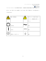


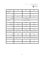
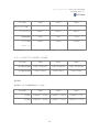
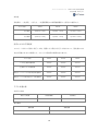
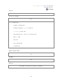
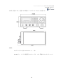
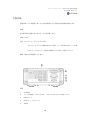
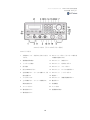
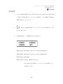


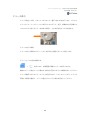

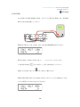

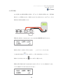
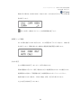


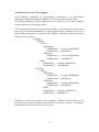


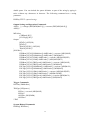


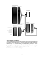
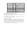
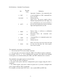
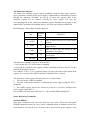
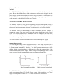
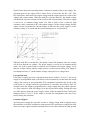
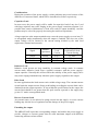

![取扱説明書[PDF:763.3KB]](http://vs1.manualzilla.com/store/data/006689553_2-1c1801da78511da10fd01a94f441ba31-150x150.png)
