1
USER’S MANUAL
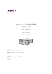
SWITCHING-MODE DC POWER SUPPLY
ARRAY 366XA
ARRAY ELECTRONIC
1
ARRAY 366XA
SWITCHING-MODE DC POWER SUPPLY
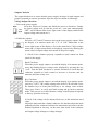
ARRAY 366XA is a series of 500W programmable switching-mode DC power
supplies with RS-232, USB (optional) and GPIB (optional) interfaces. The good
durability, simple operation, low noise, excellent output accuracy as well as the
adjustment from 0V make this series of reliable power supplies the right choice for
many applications. It provides flexible and stable DC power for various design and
test environments.
Versatile Bench-Top Features
*High definition liquid crystal display
*Full-featured keyboard and knobs
*High-efficient switching-mode power supply
*The same continuous adjustment (0-Vout) as the linear power supply
*Low ripple and noise which rivals the linear power supply
*Excellent line and load regulation
*Up to 10 operating states storage and recall
*Portable, ruggedized case and flexible system functions
*Standardized USB interface, optional GPIB and optional USB interface
*SCPI ( Standard Commands for Programmable Instruments) compatibility
*Direct setting of I/O Parameters from front-panel
2
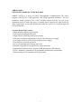
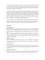
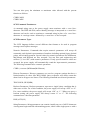
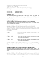
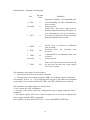
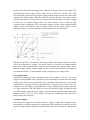
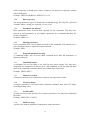
The Front Panel at a Glance
1. AC power switch
3. Earth ground terminal
5. Output on/off key
7. Control knob
9. Menu setting key
11. Current setting key
13. Store key for second function
15. Error key for second function
17. Secure key for second function
19. Clear key for second function
21. Display screen
23. REM annunciator
2. Sense terminals
4. Supply output terminals
6. Left/Right key
8. Up/Down key
10. Voltage setting key
12. Switch key for second function
14. Recall key for second function
16 Local key for second function
18. Number key
20. Enter key
22. ERR annunciator
1. AC power switch: Turns the AC power on and off.
2. Sense terminals: Tests remote voltage, the positive pole is in red, the negative pole
is in black.
3. Earth ground terminal: It is connected to the chassis and earth ground.
4. Supply output terminals: Supply output, the positive output terminal is in red, the
negative output terminal is in black.
5. Output on/off key: Turns the power supply on/off.
6. Left/Right key: Moves the blinking digit to left or right, or selects different options.
7. Control knob: Adjusts the value of the blinking digit or selects different options by
turning clockwise or counter clockwise.
8. Up/Down key: Turns the menu page.
9. Menu setting key: Enters menu setting contents.
10. Voltage setting key (VSET): Displays or modifies the present voltage setting
value.
11. Current setting key (ISET): Displays or modifies the present current setting value.
3
12. Switch key for second function (2nd): Enables the second function of other keys.
13. Store key for second function (Save): Stores the present operating states in
location “0”, “1”, … “9”.
14. Recall key for second function (Recall): Recalls a previously stored operating
state from location “0”, “1”,…“9”.
15. Error key for second function (Error): Checks or reads the error codes.
16. Local key for second function (Local): Returns the power supply to local mode
from remote control mode.
17. Secure key for second function (I/O config): Secures and unsecures the power
supply for calibration.
18. Number key (0-9 and.): Sets values.
19. Clear key for second function (Clear): Clears present input value or exits current
operation.
20. Enter key (Enter): Confirms present setting values or option.
21. Display screen: Shows parameters and status of power supply.
22. ERR annunciator: When some error is detected, ERR annunciator is on.
23. REM annunciator: When the power supply is in remote control mode, REM
annunciator is on.
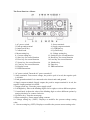
Front-Panel Display Messages
0.000V
0.000A
0.000W
OT
OV
OFF
Display present voltage value.
Display present current value.
Display present power value.
The power supply is in over-temperature state.
The power supply is in over-voltage state and the supply output is
disabled.
The output of power supply is off.
ERROR
Hardware or remote interface control commands errors are detected and
the error bits have not been cleared or read.
Unreg
The present output of the power supply is unregulated. (The output is
neither CV nor CC.)
The output of power supply is in CV mode.
The output of power supply is in CC mode.
CV
CC
4
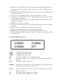
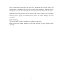
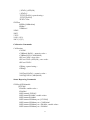
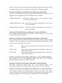
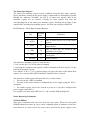
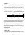
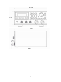
The Rear Panel at a Glance
1. AC inlet
3. RS-232 interface connector
5. Fan outlet
2. Fuse holder
4. GPIB or USB interface connector (optional)
An Introduction to this Manual
General Information
Apart from a general description of your power supply, it provides instructions for
checking your power supply, selecting power-line voltage and connecting to AC
power.
Initial Operation
It ensures that the power supply develops its rated outputs and responds to operation
from the front panel properly.
Front-Panel Operation
It describes the use of front-panel keys and knobs in detail and how to use them to
operate the power supply from the front panel. And it also shows how to configure the
power supply for the remote interface and introduces the calibration features in brief.
Remote Interface Reference
It contains the reference information to help you program the power supply over the
remote interface, and explains how to program for status reporting as well.
Application Programs
It provides some remote interface applications to help you develop programs for your
application.
5
Tutorial
It describes basic operation of the power supply and gives specific details on the
operation and use of ARRAY 366XA power supplies.
Specifications
It lists the power supply’s basic specifications.
6
Contents
Chapter 1 General Information ……………………………………...................... 11
General Information………………………………………………………………… 11
Safety Considerations………………………………………………….. ………… ...11
Description……………………………………………………………...................... 11
Installation……………………………………………………………………………12
Initial Inspection……………………………………………………….......................12
Mechanical Check……………………………………………………………………12
Electrical Check……………………………………………………………………12
Temperature Control………………………………………………………………… 12
Rack Mounting……………………………………………………………………….13
Chapter 2 Initial Operation ………………………………………………………..14
Initial Operation ……………………………………………………………………..14
Preliminary Checkout………………………………………………………………..14
Power-Line Cord……………………………………………………………………..14
Fuse Replacement……………………………………………………………………15
Power-On Checkout………………………………………………………….15
Self-test started……………………………………………………………….15
Self-test accomplished………………………………………………………..15
Enabling the outputs…………………………………………………………..15
Output Checkout……………………………………………………………….16
Voltage Output Checkout………………………………………………………16
Current Output Checkout………………………………………………………17
Chapter 3 Front Panel Operation……………………………………………20
Front Panel Operation………………………………………………………….20
Front Panel Operation Overview………………………………………………...20
Output on/off…………………………………………………………………….20
Constant Voltage Output Setting…………………………………………………21
Connecting a load to the relevant output terminals………………………………...21
Turning on the power supply……………………………………………………….21
Setting desired output voltage……………………………………………………….21
Setting maximum current……………………………………………………………21
Enabling the outputs…………………………………………………………………22
Verifying that the power supply is in the constant voltage mode………………….22
Constant Current Output Setting…………………………………………………22
Connecting a load to the relevant output terminals………………………………….22
Turning on the power supply………………………………………………………..22
Maximum output voltage setting…………………………………………………..22
Setting the desired output current……………………………………………………23
Enabling the outputs………………………………………………………………….23
Verifying that the power supply is in the constant current mode…………………..23
7
Menu Setting ………………………………………………………………………24
Main Menu Description…………………………………………………………….24
Storing and Recalling………………………………………………………………24
Error Messages Display…………………………………………………………….25
Local/ Remote Operation Switch…………………………………………………..25
Protection Function…………………………………………………………………26
Abnormal Latched State Clearance…………………………………………………26
Over-Voltage…………………………………………………………………………26
Over-Temperature…………………………………………………………………….26
The Power Supply Calibration……………………………………………………….27
Calibration Instrument………………………………………………………………..27
Cautions……………………………………………………………………………..27
Calibration Procedures………………………………………………………………27
Chapter 4 Remote Interface Reference ………………………………………….31
Remote Interface Reference………………………………………………………….31
SCPI Command Summary…………………………………………………………31
An Introduction to the SCPI Language…………………………………………….32
Command Format Used in This Manual……………………………………………33
Command Separators………………………………………………………………..34
Using the MIN and MAX Parameters……………………………………………….34
Querying Parameter Settings…………………………………………………………34
SCPI Command Terminators……………………………………………………….35
SCPI Parameter Types………………………………………………………………35
Numeric Parameters…………………………………………………………………35
Discrete Parameters………………………………………………………………….35
Boolean Parameters………………………………………………………………….35
String Parameters……………………………………………………………………35
Output Setting and Operation Commands…………………………………………..36
Trigger Commands………………………………………………………………….36
System-Related Commands…………………………………………………………36
Calibration Commands………………………………………………………………37
Status Reporting Commands……………………………………………………….37
RS-232 Interface Commands……………………………………………………….38
Simplified Programming Overview…………………………………………………38
Using the APPLy Command……………………………………………………….38
Using the Low-Level Commands………………………………………………….38
Selecting a Trigger Source…………………………………………………………39
Using the APPLY Command………………………………………………………39
Output Setting and Operation Commands………………………………………….40
Measurement Commands…………………………………………………………..40
Output on/off and Tracking Operation Commands………………………………….41
Output Setting Commands………………………………………………………….41
Trigger Source Choice………………………………………………………………43
8
Bus (Software) Triggering…………………………………………………………43
Immediate Triggering……………………………………………………………….44
Trigger Commands……………………………………………………………….44
System-Related Commands………………………………………………………….44
Calibration Commands……………………………………………………………….47
RS-232 Interface Commands………………………………………………………48
The SCPI Status Registers…………………………………………………………48
What is an Event Register?.......................................................................................48
What is an Enable Register?.....................................................................................49
The Questionable Status Register……………………………………………………50
The Standard Event Register…………………………………………………………51
The Status Byte Register……………………………………………………………53
Status Reporting Commands……………………………………………………….53
SCPI Conformance Information……………………………………………………55
SCPI Confirmed Commands…………………………………………………….55
Device-Specific Commands………………………………………………………57
Chapter 5 Application Programs………………………………………………….58
Application Programs………………………………………………………………...58
RS-232 Operation Using QuickBACSIC ………………………………………….58
Chapter 6 Tutorial………………………………………………………………….59
Tutorial……………………………………………………………………………….59
An Overview of ARRAY 366XA Operation…………………………………………59
Output Characteristics………………………………………………………………59
Unregulated State…………………………………………………………………….60
Unwanted Signals…………………………………………………………………….60
Connecting the Load………………………………………………………………..61
Output Isolation………………………………………………………………………61
Multiple Loads……………………………………………………………………..61
Considerations……………………………………………………………………….62
Capacitive Load……………………………………………………………………..62
Inductive Load………………………………………………………………………..62
Pulse Load……………………………………………………………………………62
Reverse Current Load………………………………………………………………62
Extending the output………………………………………………………………..62
Reliability………………………………………………………………………….63
Chapter 7
Specifications ……………………………………………………..64
Specifications………………………………………………………………………..64
Performance Specifications………………………………………………………….64
Transient Response Time……………………………………………………………65
Command Processing Time………………………………………………………….65
Supplemental Characteristics………………………………………………………65
9
APPENDIX
Error Messages …………………………………………………68
Error Messages…………………………………………………………………….68
Execution Errors…………………………………………………………………….68
Self-Test Errors……………………………………………………………………….71
Calibration Errors ……………………………………………………………………72
10
Chapter 1 General Information
General Information
This chapter provides a general description of your power supply. And it also contains
instructions relate to initial inspection, selecting the power-line voltage, and
connecting your power supply to AC power.
Safety Considerations
This power supply is a safety instrument with a protective earth terminal. The
terminal must be connected to earth ground through a power source with a 3-wire
ground receptacle when being connected to AC power supply.
Before installation or operation, please check the power supply and read safety
markings and instructions introduced in this manual first. Please see relevant chapters
for related specific information about safety operations.
Description
ARRAY 366XA is a series of programmable switching-mode DC power supply with
stable voltage and constant current. The excellent line and load regulation, extremely
low ripple and noise make it well suited as a high preference power system. 366XA,
as a kind of high-efficient switching-mode supply, features wide supply input voltage
from 100-240AC, high power factor and a minimum output of 0V.
Output voltage or current can be adjusted independently from front panel, or
controlled over RS-232, USB, or GPIB interface. Buttons and knobs on the front
panel can be used to adjust voltage and current of a selected output; calibrate again
without opening the case when the precision falls down (including change password
for calibration); switch the power supply from remote control mode to local mode; set
and monitor the power supply over remote interface; monitor the setting and output of
power supply via the liquid crystal display in front panel, and all the status indication,
error information displayed during working.
When being controlled over remote interface, it can be used both as a listener and a
speaker at the same time. The power supply can be set and data can be returned over
RS-232, USB, or GPIB interface by an external controller. The following functions
can be performed through RS-232, USB, or GPIB interface:
* Voltage and current setting
* Voltage and current readback
* Enable or disable track mode
* Present and stored status readback
* Programming syntax error detection
* Calibration
* Output on/off
* System self-test
11
This power supply is equipped with a liquid crystal display for displaying the output
of voltage and current. A 5-digit voltage and a 5-digit current could show the actual or
setting value of a selected supply simultaneously. And the liquid crystal display can
show the current mode of power supply。
Connections to the power supply’s output and to chassis ground are made to binding
terminals on the front panel. The Sense terminals can remotely sample the power
supply’s voltage. The positive and negative terminals of each output can be grounded,
or kept a certain voltage with the chassis ground. But voltage between each output
and the chassis ground should be kept within ±240 Vdc. The power supply is provided
with a detachable 3-wire grounding type power cord. The AC line fuse is on the rear
panel. It can be extracted for replacement when needed.
The power supply can be calibrated from the front panel directly without opening the
cabinet. Correction factors are stored in non-volatile memory. You can guard against
unauthorized calibration by using the “Standard” calibration protection function.
Installation
Initial Inspection
When you receive your power supply, please check it for any obvious damage that
may have occurred during shipment or resulted from other reasons. If any damage is
found, contact the carrier and the Sales Office immediately in order to deal with it in
time.
Keep the original packing materials in case the power supply has to be returned to
Array for repairing in the future. If you return the power supply for service, please
attach a tag identifying the owner and model number. A brief description of the
malfuction is also needed.
Mechanical Check
This check confirms that there are no broken keys or knob, and that the cabinet and
panel surfaces are free from dents and scratches, and that the display is not scratched
or cracked as well.
Electrical Check
Please see Chapter 2 for an initial operation procedure. When successfully completed,
it can be convinced that the power supply is operating in accordance with its
specifications.
Temperature Control
The power supply’s performance will not be affected when operating within the
temperature range of 0°C to 40°C, and within the temperature range of 40°C to 55°C,
12
the over-temperature protection may take effect, depending on the input voltage and
output power. A brushless fan is used to cool the power supply by drawing cool air
through the two sides and exhausting the heat through the fan outlet on the rear panel.
Sufficient space must be left at the rear and two sides of the cabinet for air circulation
when the power supply is installed. Please remove the rubber bumpers for rack
mounting.
Rack Mounting
The power supply could be installed in a standard 19-inch rack.
Please remove the rubber bumpers at the front and end of power supply before
installing.
13
Chapter 2 Initial Operation
Initial Operation
This chapter mainly focuses on three basic tests which should be performed before the
operation of the power supply: the preliminary checkout, the power-on checkout, and
the output checkout. The preliminary checkout is to check if the power supply could
run correctly. The power-on test includes a self-test that checks the internal
microprocessors and checks if the user are allowed to examine the display at the front
panel under the condition of applying power to the supply properly. The output check
ensures that the power supply develops its rated outputs and properly responds to
operation from the front panel.
In order to make sure the power supply is in accordance with
what is required and have a better command of power supply
features for later use, it is suggested that both the experienced
and the inexperienced users should read this chapter prior to
operation
Preliminary Checkout
ARRAY 366XA power supply can be used from a rated 100 V to 240 V single phase
AC power source at 47 to 63 Hz. There is an indication below the AC power inlet on
the rear panel showing the rated input voltage set for the power supply at the factory.
Power-Line Cord
The power supply is shipped from the factory with a power-line cord that has a plug
appropriate for your location. Please contact the nearest ARRAY Sales and Service
Office if the wrong power-line cord is included with your power supply. Your power
supply is equipped with a 3-wire grounding type power cord with a diameter of
1mm2X3 and the third conductor is the ground lead. The power supply can operate
properly only when the power-line cord is plugged into an appropriate receptacle. Do
not operate your power supply without adequate cabinet ground connection.
14
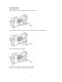
Fuse Replacement
1 Replace the fuse
Step 1: Remove the fuse-holder below AC power inlet.
Step 2: Replace the fuse with the correct one that meets the requirements.
Step 3: Put back the fuse holder.
For 115V AC operation, 10AT fuse must be used;
For 230V AC operation, 6AT fuse must be used.
15
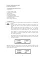
Power-On Checkout
The power-on test includes an automatic self-test that checks the internal
microprocessors and a system self-test after the power supply is turned on, and
examines the information relate to self-test process shown on the front panel. You will
observe the following sequence on the display:
1. Self-test started
It begins with an initial operation immediately after pressing the power
switch on. Then self-test starts, involving the test of internal
microprocessor and whole power supply system.
2. Self-test accomplished
If there is no error or abnormity has been detected during self testing, the supply will
enter into power-on/reset state and the output will be disabled.
In this figure, “OFF” indicates that supply output is forbidden.
3. Enabling the outputs
Press “Output on/off” to enable the outputs. The “OFF” annunciator on the
lower right corner of the display turns off, while the “ON” and “CV”
annunciators at the same place turn on. And the display switches to
monitor mode automatically to monitor the actual value of output voltage
and current.
If power-on self-test has detected any error or abnormity, the
“ERROR”annunciator is lit. For specific information about errors, please
see related chapters in appendix.
16
Output Checkout
The output checkout is to ensure that the power supply develops its rated outputs and
properly responds to various operations. Specific steps are shown as followings:
Voltage Output Checkout
1. Turn on the power supply.
Press the “Power-on” button, and finish the power-on checkout. Usually
the power supply will go into the power-on / reset state automatically.
“OFF” will be shown in the lower right corner of the display and both the
output voltage and current are 0.
2. Enable the outputs.
Press the “OUT on/off” button to turn on the power supply outputs. Now
the display is in monitor mode; the “CV” or “ON” annunciator in the
lower right corner of the display is lit. At the same time a 5-digit voltage
meter and a 5-digit current meter are displayed, respectively showing the
actual value of output voltage and current of the power supply.
3. Check if the voltmeter properly responds to knob control on front
panel for the supply.
Knob Checkout
When the power supply output is on and the display is in monitor mode,
move the blinking digit to voltage value displayed by pressing the key
“Left”. Turn the knob clockwise or counter clockwise to check that the
voltmeter responds to knob control to increase or decrease and the
ammeter indicates nearly zero.
Key Checkout
When the power supply output is on and the display is in monitor mode,
press key “VSET”, the voltage setting value in the LCD will blink. Press
the number keys on front panel directly to set voltage value needed.
Then press “Enter” to verify and finish setting and go back to monitor
mode. This process is to check that the voltage value displayed responds
to the key operation correctly.
4 Check if the voltage can be adjusted from zero to the maximum rated
value.
Adjust the knob until the voltmeter indicates 0V and then adjust the knob
gradually until the voltmeter indicates the maximum rated value with the
method explained in last step. At the same time check if the voltmeter
and output voltage changes as voltage changes.
17
Current Output Checkout
1. Turn on the power supply.
Press “Power-on” button and finish the power-on checkout. Usually the
power supply will go into the power-on / reset state automatically and
the “OFF” annunciator in the lower right corner of the LCD turns on.
Both the voltage value and current value are 0.
2. Connect a short across (+) and (-) output terminals of the supply with
an insulated test lead. The sectional area of the shorting stub should be
larger than 1.5mm2.
3. Enable the outputs.
Set the supply voltage to 5V according to the voltage setting measure.
Press the “OUT on/off” button, the display is in monitor mode. At the
same time a 5-digit voltage meter and a 5-digit current meter are
displayed, showing the actual value of output voltage and output current
of the power supply respectively. The CV or CC modes depend on the
resistance of the test lead.
4. Adjust the voltage limit value to 1.0 V.
Adjust the voltage limit to 1.0 V to assure CC operation. Please see
related chapters about voltage and current setting from front panel in this
manual for specific operations.
5. Check that the front-panel ammeter properly responds to the key and
knob operations form the front panel.
Knob Checkout
When the output of the power supply is turned on and the display is in
monitor mode, press “Right” key to move the blinking digit to current
value displayed, and turn the knob clockwise or counter clockwise to
check if the current value displayed increases or decreases as current
changes.
Key Checkout
When the output of the power supply is turned on and the display is in
monitor state, press “ISET” and the current setting value is blinking.
Press the number keys on front panel directly to set current value needed.
Then press “ENTER” to verify and finish setting and go back to monitor
mode. This process is to check that the current value displayed responds
to the key operation correctly.
18
6. Ensure that the current can be adjusted from 0A to the maximum rated
value.
Adjust the knob until the ammeter indicates 0A and then until the
ammeter indicates the maximum rated value.
If an error has been detected during the output checkout procedures, the
ERROR annunciator will turn on. Refer to the related chapters in
appendix for more specific error information.
19
Chapter 3 Front Panel Operation
Front Panel Operation
`
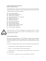
3.1 Front Panel Operation Overview
• Output on/off
• Constant Voltage setting
• Constant Current setting
• Menu Setting
• Storing and Recalling
• Error Messages Display
• Local/Remote Operation switch
• Protection Function
•Power Supply Calibration
3.2 Output on/off
The output of the power supply could be switched on or off through this
button.
When the output of the power supply is disabled, you can enable it by
pressing “Out on/off” key, and it can be turned off by pressing this key
again.
When the output of the power supply is enabled, “CV”, “CC” or “Unreg”
will be displayed in the lower right corner of the display. “CV” indicates
that the supply source is in constant voltage state, “CC” indicates that the
power supply is in constant current state and “Unreg” indicates that the
power supply is operating in unstable state (Neither in constant voltage
nor constant current status).
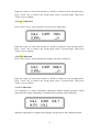
For example: if the power supply output is in constant voltage state, the
actual output voltage is 5V and the actual output current is 3A, the display
will show as follows:
When the output of the power supply is off, the “OFF” annuciator in the lower left
corner of the display is lit and the keys as well as the knobs are still valid. Then the
display will show as follows:
20
When it is operated from remote interface, inputting the following command can
enable or disable the output: OUTPUT ON/OFF. You can turn on the output by
selecting ON and turn off the output by selecting OFF.
3.3 Constant Voltage Output Setting
Constant voltage output is the most common output of the power supply. The voltage
outputs at a constant value in constant voltage output mode, and it will not change
with the load while the current will. The CV annunciator in the lower left corner of
the LCD will turn on when the power supply is in constant voltage mode. Then the
operation procedures of constant voltage output will be introduced with examples.
1. Connecting a load to the relevant output terminals
Turn off the power supply. Connect the load to the relevant output terminals. Connect
the positive pole of the load to “+” terminal of the output, and connect the negative
pole to “-” terminal of the output.
2.
Turning on the power supply
Press the “Power on/off” button in the front panel. The power supply will go into
power-on/ reset state, namely the power supply is off.
3. Setting desired output voltage
The desired output voltage can be set directly by pressing number keys or using
“Left/Right” key together with the knob.
1). Using number keys and “Enter” key to input:
① Press “Vset” to enter into voltage setting state.
② Input the desired voltage value by pressing number keys. “Clear” key can be used
to clear the wrong value to input again.
③ Press “Enter” key to confirm the voltage setting value.
2). Using “Left/Right” keys, knob and “Enter” key to input:
① Press “Vset” to enter into voltage setting state.
② Press “Left/Right” keys to move the blinking digit to the relevant digit of the
value.
③ Increase or decrease the relevant value by turning the knob clockwise or counter
clockwise. Then use “Left/Right” keys to move to the next digit to modify.
④ Press “Enter” key to confirm the voltage setting value.
4.Setting maximum current
The maximum current can be set directly by pressing the number keys or using
“Left/Right” keys together with the knob.
1). Using number keys and “Enter” key to input:
① Press “Iset” key to enter into current setting state.
21
② Input the desired current value by pressing number keys. “Clear” key can be used
to clear the wrong value to input again.
③ Press “Enter” key to confirm the current setting value.
2). Using “Left/Right” keys, knob and “Enter” key to input:
① Press “Iset” key to enter into current setting state.
② Press “Left/Right” keys to move the blinking digit to the relevant digit of the
value.
③ Increase or decrease the relevant value by turning the knob clockwise or
counterclockwise, then use “Left/Right” keys to move to the next digit to modify.
④ Press “Enter” key to confirm the current setting value.
5. Enabling the outputs
Press the “Output on/off” key to enable the outputs. “CV” is displayed in the lower
right corner of the display.
6. Verifying that the power supply is in the constant voltage mode
When you operate the power supply in the constant voltage (CV) mode, if “CC” is
displayed in the lower left corner of the display, it indicates that the actual output
current value has reached our setting value. Therefore please choose a higher current
limit value.
3.4 Constant Current Output Setting
When the power supply is in constant current mode, the current will output at a
constant value, and it will not change with the load while the voltage will. The CC
annunciator in the lower right corner of the display will turn on when the power
supply is in constant current mode. The operation methods of constant current output
are introduced in the following.
1. Connecting a load to the relevant output terminals
Turn off the power supply. Connect the load to the relevant terminals. Connect the
positive pole of the load to “+” terminal of the output, and connect the negative pole
to “-” terminal of the output.
2. Turning on the power supply
Press the “Power on/off” button in the front panel. The power supply will go into
power-on/ reset state, namely the power supply is off.
3. Maximum output voltage setting
Maximum output voltage can be set directly by pressing number keys or using
“Left/Right” key together with the knob.
1). Using number keys and “Enter” key to input:
① Press “Vset” to enter into voltage setting state.
② Input the desired voltage value by pressing number keys. “Clear” key can be used
to clear the wrong value to input again.
③ Press “Enter” key to confirm the voltage setting value.
2). Using “Left/Right” keys, knob and “Enter” key to input:
① Press “Vset” to enter into voltage setting state.
22
② Press “Left/Right” keys to move the blinking digit to the corresponding digit of
the value.
③ Increase or decrease the relevant value by turning the knob clockwise or counter
clockwise, then use “Left/Right” keys to move to the next digit to modify.
④ Press “Enter” key to confirm the voltage setting value.
4. Setting the desired output current
The desired current can be set directly by pressing the number keys or using
“Left/Right” keys together with the knob.
1). Using number keys and “Enter” key to input:
① Press “Iset” to enter into current setting state.
② Input the desired current value by pressing number keys. “Clear” key can be used
to clear the wrong value to input again.
③ Press “Enter” key to confirm the current setting value.
2). Using “Left/Right” keys, knob and “Enter” key to input:
① Press “Iset” to enter into current setting state.
② Press “Left/Right” keys to move the blinking digit to the corresponding digit of
the value.
③ Increase or decrease the relevant value by turning the knob clockwise or counter
clockwise, then use “Left/Right” keys to move to the next digit to modify.
④ Press “Enter” key to confirm the current setting value.
5. Enabling the outputs.
Press the “Output on/off” key to enable the outputs. “CC” is displayed in the lower
left corner of the display.
6. Verifying that the power supply is in the constant current mode
When the power supply is operating in the constant current mode, if the “CV” is
displayed in the lower left corner of the display, it indicates that the actual output
voltage value has reached our setting value. Therefore please choose a higher voltage
limit.
23
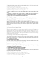
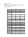
3.4 Menu Setting
3.4.1 Main Menu Description
Press “Menu” key to enter into main menu, which is showed as follows:
Function and Parameter
Current Limit:
14.600A
Voltage Limit:
35.200V
Voltage Over:
36.000V
Beep:
*On
Off
Knob:
*On
Off
Interface:
*RS232 USB GPIB
Baud Rate
4800 *9600
RS232 Interface
Description
Current Limit:
Current Limit Value
Voltage Limit:
Voltage Limit Value
Voltage Over:
Over Voltage Value
Beep:
On
Off
Knob:
On
Off
Interface Choices:
RS232 USB GPIB
Baud Rate Setting
300 600 1200 2400 4800 9600 19200
38400
Parity Check
None Even Odd
Data Bit:
5
6
7
*8
Stop Bit:
*1 2
Flow Control:
*On Off
Selecting USB
GPIB Address:
Address Value
Parity Check
*None Even Odd
Data Bit:
5
6
7
*8
Stop Bit:
*1 2
Flow Control:
*On Off
USB Interface
GPIB Interface
GPIB Address:
5
Notes: Except the parameters about knob, key sound and interface configuration,
other parameters in the main menu will not be saved when the power supply is
switched off. If you would like to store relevant parameters, please press “2nd” +
“Save” keys or make use of *sav command.
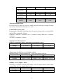
3.6 Storing and Recalling
Store and recall procedures are illustrated in the following:
1 Press “2nd” + “Save” keys to enter into electronic store menu, or press “2nd” +
“Recall” keys to enter into electronic recall men
2 Press keys or adjust the knob to select store or recall location (0~9).
3 Press “Enter” key to confirm and exit store or recall menu simultaneously. For a
store case, voltage and current values are saved in corresponding EEPROM and for a
24
recall condition, the voltage and current values stored previously can be retrieved
from corresponding EEPROM and set as present values.
Example 1: Set voltage to 5V and current to 2A. Then turn on the power supply and
save this state to the EEPROM specified by Location 1.
Step
Operational Details
Display Information
Set voltage to 5V and current to 2A. Then turn
5.000V 2.000A
1
on the power supply.
0.000W CV
Press “2nd” + “Save” keys to enter into store
2
Save:0
menu.
Press keys or adjust the knob to select store
3
Save:1
location as 1.
Press “Enter” key to confirm and exit store
5.000V 2.000A
4
menu simultaneously.
0.000W CV
Example 2: Based on Example 1, set voltage to 30V. Then turn off the power supply
and recall the values saved in the EEPROM specified by Location 1.
Step
Operational Details
Display Information
Set voltage to 30V. Then turn off the power
30.000V 0.000A
1
supply.
0.000W OFF
Press “2nd” + “Recall” keys to enter into
2
Recall:0
recall menu.
Press keys or adjust the knob to select recall
3
Recall:1
location as 1.
Press“Enter” key to confirm and exit recall
5.000V 2.000A
4
menu simultaneously.
0.000W CV
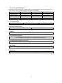
3.7 Error Messages Display
If some error has been detected, “err” annunciator will be lit. Then you can read the
error messages through front panel operation with following steps:
1 Press “2nd” + “Error” keys and the display will show the error messages.
Example 1: if there is a wrong command, “err” annunciator will turn on. Then check
the error messages with following steps:
Step
Operational Details
Display Information
1
Press “2nd” +“Error” keys and the display
ERROR -103
will show the error messages.
2
If some error has been detected, repeat the
first step.
3
When there is no error, “err” annunciator will
be off. Repeat the first step, then “NO
NO ERROR
ERROR” will be showed in the display.
3.8 Local/ Remote Operation Switch
If it is need to operate the power supply from the keys and knobs in the front panel,
the power supply must keep in local control state. And the power supply will stay in
25
this state as soon as it is switched on.
In remote control state, all keys and knobs become invalid (except “2nd” and
“Local” keys). When the power supply receives the remote command (SYST:REM)
through RS232 Interface or commands through GPIB Interface, REM annunciator will
be on and remote control becomes valid. In remote control state, all operations of the
power source are controlled by remote controller. After receiving the command
demanding the power supply to return to local control (eg. SYST:LOC ), the power
supply will go back to local control state and REM annunciator will be off. In remote
control state, the power supply can be returned to local control state by pressing “2nd”
+“Local” keys even if it has not received the returning command.
3.9 Protection Function
There are two protections states: over-voltage protection and over-temperature
protection for 3662A. Once anything abnormal is detected, the corresponding state
symbol in the State Register will be set; the power supply will disable its output and
beep to give an alarm; the display reveals the reason for the unusual condition and the
power supply enters into abnormal latched state. Except specific operations, the
supply will stop responding to other commands. For example: when the temperature
is too high, supply output will turn off and beep to give an alarm. OT will be showed
in the lower right corner of the display and the power supply will not respond to other
commands.
3.9.1 Abnormal Latched State Clearance
When the power supply enters into abnormal latched state, it fails to respond to other
commands. Only when the abnormal latched state is cleared by pressing “2nd” +
“Clear” keys, can normal operations be restored. Obviously, the reason for the
abnormal latch must be solved, or the power supply will enter into abnormal latched
state once again immediately.
3.9.2 Over-Voltage
The user can set the over-voltage protection value (Voltage Over) in the menu as
needed. When supply output voltage is higher than the set value, the system enters
into over-voltage protection status and the display shows OV. This state can be cleared
by decreasing the output voltage or increasing the over-voltage protection value.
Otherwise, even though you can remove the latched state by pressing “2nd” + “Clear”
keys, the system will automatically enter over-voltage protection status once again for
over-voltage.
3.9.3 Over-Temperature
If the internal temperature of the supply is above the safety limitation,
over-temperature protection will be triggered; the supply output will turn off and OT
is displayed. In the meantime, OT and PS in the Questionable Status Register will be
set and keep in this state until they are reset and over-temperature state is removed.
You can’t clear the abnormal latched state until the supply temperature falls to its
26
normal range.
The Power Supply Calibration
Because various factors may cause the reduction of the power supply’s output
precision after it has been used for a period of time, the user should calibrate the
power supply’s output to make the output return to the previous precision. But it is
suggested that the power should not be calibrated frequently. This section mainly
introduces how to unsecure the power supply and the detailed procedures of manual
calibration.
Calibration Instrument
Multimeter (DVM)
FLUKE 45: measures the DC current
KEITHLEY 2000: measures the DC voltage
Power supply: CHROMA 61601 AC power supply
Cautions
● When the calibration is conducted, the ambient temperature should be within the
range of 25℃±2℃. All testing instruments and the supply power must be
preheated for 30 minutes before the calibration.
● As when the FLUKE 45 measures a current as high as 9.5A, the sample resistance
temperature will increase and give rise to a change in resistance value, you should
test the high current as soon as possible.
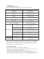
Calibration Procedures
Press the “Vset” key and the display will show as follows:
Press “secure” key after pressing “2nd” key and you will see the following graph:
Input the password “003662”, then press “Enter” key to enter into calibration menu,
which is shown as below:
27
Select CV, CC or OV mode calibration by direction key. If “DEF” is selected, all
calibration parameters are restored to default value. CV, CC and OV mode should be
calibrated one by one, which is the correct calibration sequence. Return to calibration
menu after each mode calibration is completed. Press “Clear” key to exist calibration
state.
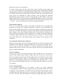
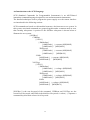
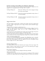
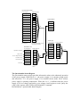
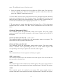
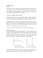
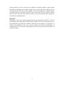
3.1 CV Mode Calibration
In this mode, three voltage points: 0.5V、22V、34.5V should be calibrated.
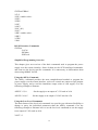
3.1.1 Wiring
+
+
OUTPUT
KEITHLEY 2000
366XA
+
-
SENSE
3.1.2 0.5V Calibration
Press “Enter” key, you will see the following figure in the display:
Input the value you read from KEITHLEY 2000, which is retained to four decimal
places. Press “Clear” key to remove the wrong input value of current digit. Then press
“Enter” key to confirm.
3.1.3 22 V Calibration
Press “Enter” key to verify and then you will see the followings:
Input the value you read from KEITHLEY 2000, which is retained to four decimal
places. Press “Clear” key to remove the wrong input value of current digit. Then press
28
“Enter” key to confirm.
3.1.4 34.5V Calibration
Press “Enter” key to verify and then the display will show as follows:
Input the value you read from KEITHLEY 2000, which is retained to four decimal
places. Press “Clear” key to remove the wrong input value of current digit. Then press
“Enter” key to confirm and exit to calibration menu. Now, voltage calibration is
completed.
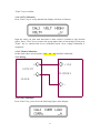
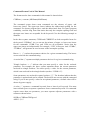
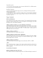
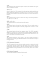
3.2 CC Mode Calibration
In this mode, three current points: 0.5A、6A、9A should be calibrated.
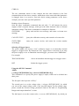
3.2.1 Wiring
+10A
+
OUTPUT
FLUKE45
366XA
-
3.2.2 0.5A Calibration
Press “Enter” key, you will see the following figure in the display:
29
Input the value you read from FLUEK 45, which is retained to four decimal places.
Press “Clear” key to remove the wrong input value of present digit. Then press
“Enter” key to confirm.
3.2.3 6A Calibration
Press “Enter” key to verify and then you will see the followings:
Input the value you read from FLUEK 45, which is retained to four decimal places.
Press “Clear” key to remove the wrong input value of present digit. Then press
“Enter” key to confirm.
3.2.4 9A Calibration
Press “Enter” key to verify and then the display will show as follows:
Input the value you read from FLUEK 45, which is retained to four decimal places.
Press “Clear” key to remove the wrong input value of present digit. Then press
“Enter” key to confirm.
3.3 OV Calibration
OV calibration is a kind of automatic calibration without manual operation, which
starts after the voltage calibration is conducted and is shown in the following:
When the calibration is completed, the display will go back to the calibration menu.
30
Chapter 4 Remote Interface Reference
Remote Interface Reference
A detailed description of how to use the remote interface will be given in this chapter,
which includes how to program the power supply through the remote interface, the
commands format and matters need attention.
z
z
z
z
z
z
z
z
z
z
z
z
z
SCPI Command Summary
Simplified Programming Overview
Using the Apply Command
Output Setting and Operation Commands
Triggering Commands
System-Related Commands,
Calibration Commands
RS-232 Interface Commands
The SCPI Status Registers
Status Reporting Commands
An Introduction to the SCPI Language
Halting an Output in Progress
SCPI Conformance Information
If this is the first time you use the SCPI language, it is suggested intensely to read this
chapter attentively in order to become familiar with the language before you attempt
to program the power supply.
SCPI Command Summary
This section mainly introduces the SCPI (Standard Commands for Programmable
Instruments) commands available to program the power supply. Refer to the later
sections in this chapter for more complete details on the format and function of each
command.
Each SCPI command presented in this section uses the following conventional format.
1.
Square brackets ([ ]) indicate optional keywords or parameters.
2.
Braces ({ }) enclose parameters within a command string.
3. Triangle brackets (< >) indicate that you must substitute a value or a code for the
enclosed parameter.
4.
A vertical bar ( | ) separates one of two or more alternative parameters.
31
An Introduction to the SCPI Language
SCPI (Standard Commands for Programmable Instruments) is an ASCII-based
instrument command language designed for test and measurement instruments.
The detailed techniques used to program the power supply over the remote interface
are introduced in the following sections.
SCPI commands are based on a hierarchical structure, also known as a tree system. In
this system, associated commands are grouped together under a common node or root,
thus forming subsystems. A portion of the SOURce subsystem is shown below to
illustrate the tree system.
[SOURce:]
CURRent
[:LEVel]
[:IMMediate]
[:AMPLitude] {<current>|MIN|MAX}
[:AMPLitude]? [MIN|MAX]
:TRIGgered
[:AMPLitude] {<current>|MIN|MAX}
[:AMPLitude]? [MIN|MAX]
:LIMit
[:AMPLitude] {<current>|MIN|MAX}
[:AMPLitude]? [MIN|MAX]
VOLTage
[:LEVel]
[:IMMediate]
[:AMPLitude] {<voltage>|MIN|MAX}
[:AMPLitude]? [MIN|MAX]
:TRIGgered
[:AMPLitude] {<voltage>|MIN|MAX}
[:AMPLitude]? [MIN|MAX]
:LIMit
[:AMPLitude] {<voltage>|MIN|MAX}
[:AMPLitude]? [MIN|MAX]
[SOURce:] is the root keyword of the command, CURRent and VOLTage are the
second-level keywords, and LIMit is the third-level keywords. A colon ( : ) separates a
command keyword from a lower-level keyword.
32
Command Format Used in This Manual
The format used to show commands in this manual is shown below:
CURRent {<current>|MINimum|MAXimum}
The command syntax shows most commands are the mixture of upper- and
lower-case letters. The upper-case letters indicate the abbreviated spelling for the
command. For shorter program lines, send the abbreviated form. For better program
readability, send the long form. But notice that only the complete spelling form and
the upper-case letters are acceptable for the keyword. Give the following example to
illustrate:
In the above syntax statement, CURR and CURRENT are both acceptable forms for
the keyword “CURRent”. As you can use the mixture of upper- or lower-case letters
for the commands, CURR, Curr, and CURr are all acceptable. Notice that the
upper-case letters are indispensable. For example, “CUR” is incorrect. And “CURRe”,
“CURRen”, will generate an error because of the incomplete spelling.
Braces “{ }” enclose the parameter choices for a given command string. The braces
are not sent with the command string.
A vertical bar “|” separates multiple parameter choices for a given command string.
Triangle brackets “< >” indicate that you must specify a value for the enclosed
parameter. For example, the above syntax statement shows the current parameter
enclosed in triangle brackets. You must specify a value for the current parameter,
which is not enclosed in the triangle bracket (such as “CURR 0.1”)..
Some parameters are enclosed in square brackets “[ ]”. The brackets indicate that the
parameter is optional and can be omitted. The brackets are not sent with the command
string. If you do not specify a value for an optional parameter, a default value will be
chosen by power supply.
A colon “:” separates a command keyword from a lower-level keyword. You must
insert a blank space to separate a parameter from a command keyword. If a command
requires more than one parameter, you must separate adjacent parameters with a
comma as shown below:
SOURce:CURRent:TRIGgered
APPL 3.5,1.5
33
Command Separators
A colon “ :” is used to separate a command keyword from a lower-level keyword as
shown below:
SOURce:CURRent:TRIGgered
A semicolon “ ;” is used to separate two commands within the same subsystem as
shown below:
SOUR:VOLT MIN;CURR MAX
The following two commands have the same effect as the above command.
SOUR:VOLT MIN
SOUR:CURR MAX
Use a colon and a semicolon to link commands from different subsystems.
For example, in the following command string, an error is generated if you do not use
the colon and semicolon:
MEAS:VOLT?;:SOUR:CURR MIN
Using the MIN and MAX Parameters
You can substitute MINimum or MAXimum for the parameter of many commands.
For example, consider the following command:
CURRent {<current>|MIN|MAX}
Instead of selecting a specific current, you can `substitute MINimum to set the current
to its minimum value or MAXimum to set the current to its maximum value.
Querying Parameter Settings
You can query the value of most parameters by adding a question mark (?) to the
command. For example, the following command sets the output current to 5A
CURR 5
You can query the value by executing:
CURR?
34
You can also query the minimum or maximum value allowed with the present
function as follows:
CURR? MAX
CURR? MIN
SCPI Command Terminators
A command string sent to the power supply must terminate with a <new line>
character. The IEEE-488 EOI (end-or-identify) message is interpreted as a <new line>
character and can be used to terminate a command string in place of a <new line>
character. A <carriage return> followed by a <new line> is also accepted.
SCPI Parameter Types
The SCPI language defines several different data formats to be used in program
messages and response messages.
Numeric Parameters: Commands that require numeric parameters will accept all
commonly used decimal representations of numbers including optional signs, decimal
points, and scientific notation. Special values for numeric parameters like MINimum,
MAXimum, and DEFault are also accepted. You can also send engineering unit
suffixes (V, A or SEC) with numeric parameters. If only specific numeric values are
accepted, the power supply will automatically round the input numeric parameters.
The following command uses a numeric parameter:
CURR {<current>|MINimum|MAXimum}
Discrete Parameters: Discrete parameters are used to program settings that have a
limited number of values (like BUS, IMM). Query responses will always return the
short form in all upper-case letters. The following command uses discrete parameters:
TRIG:SOUR {BUS|IMM}
Boolean Parameters: Boolean parameters represent a single binary condition that is
either true or false. For a false condition, the power supply will accept “OFF” or “0”.
For a true condition, the power supply will accept “ON” or “1”. When you query a
boolean setting, the power supply will always return “0” or “1”. The following
command uses a boolean parameter:
DISP {OFF|ON}
String Parameters: String parameters can contain virtually any set of ASCII characters.
A string must begin and end with matching quotes; either with a single quote or with a
35
double quote. You can include the quote delimiter as part of the string by typing it
twice without any characters in between. The following command uses a string
parameter:
DISPlay:TEXT <quoted string>
Output Setting and Operation Commands
APPLy [{<voltage>|DEF|MIN|MAX}][,{<current>|DEF|MIN|MAX}]]
APPLy?
MEASure
:CURRent[:DC]?
[:VOLTage][:DC]?
Output
[:STATe] {OFF|ON}
[:STATe]?
:TRACk[:STATe] {OFF|ON}
:
TRACk[:STATe]?
[SOURce:]
CURRent[:LEVel][:IMMediate][:AMPLitude] {<current>[MIN|MAX}
CURRent[:LEVel][:IMMediate][:AMPLitude]? [MIN|MAX]
CURRent[:LEVel]:LIMit[:AMPLitude] {<current>|MIN|MAX|DEF}
CURRent[:LEVel]:LIMit[:AMPLitude]? {MIN|MAX|DEF}
CURRent[:LEVel]:TRIGgered[:AMPLitude] {<current>[MIN|MAX}
CURRent[:LEVel]:TRIGgered[:AMPLitude]? [MIN|MAX]
VOLTage[:LEVel][:IMMediate][:AMPLitude] {<current>|MIN|MAX}
VOLTage[:LEVel][:IMMediate][:AMPLitude]? [MIN|MAX]
VOLTage[:LEVel]:LIMit[:AMPLitude] {<current>|MIN|MAX|DEF}
VOLTage[:LEVel]:LIMit[:AMPLitude]? {MIN|MAX|DEF}
VOLTage[:LEVel]:TRIGgered[:AMPLitude] {<current>[MIN|MAX}
VOLTage[:LEVel]:TRIGgered[:AMPLitude]? [MIN|MAX]
Trigger Commands
INITiate[:IMMediate]
TRIGger[:SEQuence]
:DELay {<second>|MIN|MAX}
:DELay?
:SOURce {BUS|IMM}
:SOURce?
*TRG
System-Related Commands
DISPlay[:WINDow]
36
[:STATe] {OFF|ON}
[:STATe]?
:TEXT[:DATA] <quoted string >
:TEXT[:DATA]?
:TEXT:CLEar
SYSTem
:BEEPer[:IMMediate]
:ERRor?
:VERSion?
*IDN?
*RST
*TST?
*SAV {1|2|3}
*RCL {1|2|3}
Calibration Commands
CALibration
:COUNt?
:CURRent[:DATA] < numeric value >
:CURRent:LEVel {MIN|MAX}
:SECure:CODE <new code >
:SECure:STATe {OFF|ON},<new code>
:SECure:STATe?
:STRing <quoted string >
:STRing?
:VOLTage[:DATA] < numeric value >
:VOLTage:LEVel {MIN|MAX}
Status Reporting Commands
STATus:QUEStionable
[:EVENt]?
:ENABle <enable value >
:ENABle?
:INSTrument[:EVENt]?
:INSTrument:ENABle <enable value>
:INSTrument:ENABle?
:INSTrument:ISUMmary<n>[:EVENt]?
:INSTrument:ISUMmary<n>:CONDition?
:INSTrument:ISUMmary<n>:ENABle <enable value>
:INSTrument:ISUMmary<n>:ENABle?
37
SYSTem:ERRor?
*CLS
*ESE <enable value>
*ESE?
*ESR?
*OPC
*OPC?
*PSC {0|1}
*PSC?
*SRE <enable value>
*SRE?
*STB?
*WAI
RS-232 Interface Commands
SYSTem
:LOCal
:REMote
:RWLock
Simplified Programming Overview
This chapter gives an overview of the basic commands used to program the power
supply over the remote interface. Some of them are the SCPI-confirmed commands,
and some are the device-specific commands. It is unnecessary to differentiate them
when using ARRAY 366XA.
Using the APPLy Command
The APPLy command provides the most straightforward method to program the
power supply over the remote interface, such as to control one output or triple outputs
of power supply, and to read the immediate output value of each supply. Give the
following example to illustrate:
APPLY 3.3,2.0
Set the supply to an output of 3.3V rated at 2.0A
APLLY 12.0,0.5
Set the supply to an output of 12.0V rated at 0.5A
Using the Low-Level Commands
The main feature of the low-level commands is to provide you with more flexibility to
change or query the individual parameters than the APPLy command. Give the
following example to illustrate how to use the low-level commands to set the supply
to an output of 5.0V rated at 4.0A:
VOLT 3.3
38
CURR 2.0
The two commands shown in this example has the same function as the first
command shown in the above example, which shows when some individual parameter
is changed, there is no need to enter the whole setting parameters as the above
example, just enter some specified parameter.
Reading a Query Response
Only the query commands (commands that end with “?”) will instruct the power
supply to send a response message, which gives the either returned values or internal
instrument settings. Take below commands as examples to illustrate:
SYST:ERR?
Query and read the error message, and return a relevant error
message
CAL:SEC:STAT?
Query the calibration security, and return the relevant value
SYST:VERS?
accordingly
Query the system version, and return the version number
Selecting a Trigger Source
The power supply will accept a “bus” (software) trigger or an immediate internal
trigger as a trigger source. By default, the “bus” trigger source is selected. If you want
the power supply to use an immediate internal trigger, you must select “IMMediate”.
For example:
TRIG:SOUR IMM
Select an immediate internal trigger as a trigger source
INIT
Initiate the trigger system
Using the APPLY Command
APPLy
{<voltage>|DEF|MIN|MAX}[,{<current>|DEF|MIN|MAX}]]
This command is to specify the power supply’s output, which can be divided into
three parts:
The first part is the keyword “APLLy”.
The second part is to set the voltage value {<voltage>|DEF|MIN|MAX}, by which
you can set the output voltage value of the specified supply. For the setting range,
please consult the relevant voltage parameters listed in the table of “Programming
Ranges and Output Identifiers” section.
The third part is to set the current value {<current>|DEF|MIN|MAX}, by which you
39
can set the output current value of the specified supply. For the setting range, please
consult the relevant current parameters listed in the table of “Programming Ranges
and Output Identifiers” section.
When the voltage and current are set, the “DEF|MIN|MAX” represents the default
value, the minimum value and the maximum value respectively.
For example:
APPLY 5.0,2.5
Set the supply to an output of 5.0V rated at 2.5A
Executing the low-level commands has the same effect as this
command. Please refer to the last section.
APPLy?
This command queries and returns the power supply’s present voltage and current
values for each output. For example:
APPLy? Query and return the voltage and the current set values of power
supply.
Output Setting and Operation Commands
This section describes the low-level commands used to program the output of power
supply. Although the APPLy command provides the most straightforward method to
program the output of power supply, the low-level commands give you more
flexibility to change individual parameters, which include output selection commands,
measurement commands, output on/off and tracking operation commands and output
setting commands.
Measurement Commands
MEASure:CURRent[:DC]?
This command measures and returns the current value at the present output terminals
of the power supply. The physical outputs of measurement are specified by the output
identifier. If any output identifier is not specified, the current of the selected output is
returned.
MEASure:VOLTage[:DC]?
This command measures and returns the voltage value at the present output terminals
of the power supply. The physical outputs of measurement are specified by the output
identifier. If any output identifier is not specified, the voltage of the currently selected
output is returned.
40
Output on/off and Tracking Operation Commands
Output[:STATe] {OFF|ON}
This command enables or disables the outputs of the power supply.
For example:
OUTPUT ON
OUTPUT OFF
Enable the outputs
Disable the outputs
Output[:STATe]?
This command queries the output state of the power supply and returns the
corresponding values. “OFF” shows the output is disabled, and “ON” shows the
output is enabled.
Output Setting Commands
[SOURce:]CURRent[:LEVel][:IMMediate][:AMPLitude] {<current>[MIN|MAX}
This command directly programs the immediate output current level of the output
selected with the INST command.
[SOURce:]CURRent[:LEVel][:IMMediate][:AMPLitude]? [MIN|MAX]
This command checks and returns the immediate current value at the present output
terminals of the power supply or the maximum and minimum programmable current
levels of the selected output.
For example:
CURR?
Query and return the immediate current value of the
output terminals
CURR?
MAX
Query and return the maximum programmable current
level of the output terminals.
CURR?
MIN
Qurery and return the minimum programmable current
level of the output terminals
[SOURce:]CURRent[:LEVel]:LIMit[:AMPLitude] {<current>|MIN|MAX|DEF}
This command is to set the maximum current limit value of the output selected with
INST command.
[SOURce:]CURRent[:LEVel]:LIMit[:AMPLitude]? |MIN|MAX|DEF}
This query returns the current limit level of the presently selected output or the
minimum/ maximum/ default programmable current values of the presently selected
output.
[SOURce:]CURRent[:LEVel]:TRIGgered[:AMPLitude] {<current>[MIN|MAX}
This command programs the pending triggered current level of the power supply,
41
which is a stored value and transferred to the output terminals when a trigger occurs.
A pending triggered level is not affected by subsequent CURRent commands.
[SOURce:]CURRent[:LEVel]:TRIGgered[:AMPLitude]? [MIN|MAX]
This query checks and returns the presently programmed triggered current level. If no
triggered level is programmed, present CURRent value is returned.
CURRent:TRIGgered?
Return the CURRent value or the set triggered current
level of the selected output
CURRent:TRIGgered? MAX
Return the maximum programmable current value of
the selected output
CURRent:TRIGgered? MIN
Return the minimum programmable current value of
the selected output
VOLTage[:LEVel][:IMMediate][:AMPLitude] {<voltage>|MIN|MAX}
This command directly programs the immediate output voltage level of the output
selected with the INST command.
[SOURce:]VOLTage[:LEVel][:IMMediate][:AMPLitude]? [MIN|MAX]
This command checks and returns the immediate voltage value at the present output
terminals of the power supply or the maximum and minimum programmable voltage
levels of the selected output. For example:
VOLT?
VOLT? MAX
VOLT? MIN
Query and return the immediate voltage value of the output
terminals
Query and return the maximum programmable voltage levels
of the output terminals
Query and return the minimum programmable voltage levels
of the output terminals
[SOURce:]VOLTage[:LEVel]:LIMit[:AMPLitude] {<voltage>|MIN|MAX|DEF}
This command is to set the maximum voltage limit value of the presently
programmed output selected with INST command.
[SOURce:]VOLTage[:LEVel]:LIMit[:AMPLitude]? {MIN|MAX|DEF}
This query returns the voltage limit level of the selected output, or the
maximum/minimum/default programmable voltage values of the selected output.
[SOURce:]VOLTage[:LEVel]:TRIGgered[:AMPLitude] {<voltage>[MIN|MAX}
This command programs the pending triggered voltage level of the power supply,
which is a stored value and transferred to the output terminals when a trigger occurs.
A pending triggered level is not affected by subsequent VOLTage commands.
42
[SOURce:]VOLTage[:LEVel]:TRIGgered[:AMPLitude]? [MIN|MAX]
This query checks and returns the presently programmed triggered voltage level. If no
triggered level is programmed, the VOLTage value is returned.
VOLTage:TRIGgered?
Return the VOLTage value or the set triggered voltage
level of the selected output
VOLTage:TRIGgered? MAX Return the maximum programmable voltage values of
the selected output
VOLTage:TRIGgered? MIN
Return the minimum programmable voltage values of
the selected output
Trigger Source Choice
The power supply’s system allows a change in the output of the power supply when
receiving a trigger. Triggering the power supply includes internal immediate trigger
and bus trigger.
Triggering the power supply is a multi-step process:
1. Select an output with the INST:[SELect] command and then configure the power
supply for the triggered output level by using CURRent:TRIGgered and
VOLTage:TRIGgered.
2. Specify the source from which the power supply will accept the trigger. The power
supply will accept a bus (software) trigger or an immediate trigger.
3. Set the time delay between the detection of the trigger on the specified trigger
source and the start of any corresponding output change. Notice that the time delay is
valid for only the bus trigger source.
4. Execute an INITiate[:IMMediate] command. If the IMMediate source is selected,
the selected output is set to the triggered level immediately. But if the trigger source is
the bus, the power supply is set to the triggered level after receiving the Group
Execute Trigger (GET) or *TRG command.
Selecting a Trigger Source
You must specify the source from which the power supply will accept a trigger. The
trigger is stored in volatile memory; the source is set to bus when the power supply
has been off or after a remote interface reset.
Bus (Software) Triggering
1. Select the bus trigger source by sending the following command.
TRIGger:SOURce BUS
2. Trigger the power supply from the remote interface by sending the *TRG command.
And the power supply outputs specified triggered output level after the set time delay
43
if any delay is given.
3. You can also select the trigger source from the USB, RS-232 or GPIB interface.
The operation has been introduced before.
Immediate Triggering
1. Select the internal immediate trigger source by sending the following command:
TRIGger:SOURce IMM
2. If the IMMediate source is selected as a trigger source, once the trigger command is
executed, the power supply outputs triggered output voltage and current immediately.
Any delay is ignored.
Trigger Commands
INITiate[:IMMediate]
This command causes the trigger system to initiate. This command initiates the trigger
subsystem when the trigger source is bus and completes one full trigger cycle when
the trigger source is the internal immediate.
TRIGger[:SEQuence]:DELay{<second>| MINimum | MAXimum}
This command sets the time delay between the detection of an event on the specified
trigger source and the start of any corresponding trigger action on the power supply
output. Select from 0 to 3600 seconds. MIN = 0 second. MAX = 3600 seconds. At
*RST, this value is set to 0 second.
TRIGger[:SEQuence]:DELay?
This command queries the trigger delay set by bus.
TRIGger[:SEQuence]:SOURce {BUS | IMMediate}
This command selects the source from which the power supply will accept a trigger.
The power supply will accept a bus trigger or an internal immediate trigger. At *RST,
the bus trigger source is selected.
TRIGger[:SEQuence]:SOURce?
This command queries the present trigger source and returns “BUS” or “IMM”.
*TRG
This command generates a trigger to the trigger subsystem that has selected a bus
trigger as its source. The command has the same effect as the Group Execute Trigger
(GET) command.
System-Related Commands
DISPlay[:WINDow][:STATe] {OFF | ON}
This command turns the front-panel display on or off. When the display is turned off,
44
messages are not sent to the display and all annunciators are disabled except the
“ERROR” and “Rmt” annunciators.
The display state is automatically turned on when you return to the local mode. After
pressing the “Local” key to return to the local state from the remote interface, press
any key except for the number keys, knobs, “Resolution”, “Clear”, ”Enter”, and
“Track” keys, or “power-on/reset” key to switch to the display status
automatically.
DISPlay[:WINDow][:STATe]?
This command queries the front-panel display setting and returns “0” (OFF) or “1”
(ON).
DISPlay[:WINDow]:TEXT[:DATA] <quoted string>
This command displays a message on the front panel. The power supply will display
up to 12 characters in a message in the form of English letters, Arabic numerals and
the blank spaces. Any additional characters are truncated. Each special mark is
displayed in the form of the blank space with individual display space. (Except for the
single quotes, because which indicate the start and the end of the character string
message.) The power supply will not send the output to the display when a message is
shown on the front panel.
DISPlay[:WINDow]:TEXT[:DATA]?
This command queries the message sent to the front panel and returns a quoted string.
DISPlay[:WINDow]:TEXT:CLEar
This command clears the message displayed on the front panel, and makes the display
exit the character string displaying mode to switch to the immediate mode
automatically.
SYSTem:BEEPer[:IMMediate]
This command makes the power supply generates a single beep immediately.
SYSTem:ERRor?
This command queries the power supply’s error queue. When “ERROR” annunciator
in the front panel turns on, one or more command syntax or hardware errors have
been detected. At present, if this command is sent to the power supply through remote
interface, the power supply can return corresponding error messages. Up to 20 errors
can be stored in the error queue.
SYSTem:VERSion?
This command queries the power supply to determine the present SCPI version. The
returned value is a string in the form YYYY.V where the “YYYY” represent the year
of the version, and the “V” represents a version number for that year (for example,
1995.0).
45
*IDN?
This query command reads the power supply’s identification string. The power supply
returns four fields separated by commas. The first field is the manufacturer’s name,
the second field is the model number, the third field is reserved (always “0”), and the
fourth field is a version code which contains three numbers. The first number of the
version code is the firmware version number for the main power supply processor; the
second is for the input/output processor; and the third is for the front-panel processor.
For example:
ARRAY,3662A,0,1.3-1.0-1.5
*RST
This command resets the power supply to its power-on state.
Command
State
CURR[:LEV][:IMM] Output dependent value※
CURR[:LEV]:TRIG
Output dependent value※
DISP[:STAT]
ON
INST[:SEL]
P6V
INST:COUP
NONE
OUTP[:STAT]
OFF
OUTP:TRAC
OFF
TRIG:DEL
0
TRIG:SOUR
BUS
VOLT[:LEV][:IMM] 0
VOLT[:LEV]:TRIG
0
The reset operation sets the output current to the maximum value.
*TST?
This query performs a complete self-test of the power supply and returns “0” if the
self-test passes or “1” if it fails.
*SAV { 0| 2 | ……|9 }
This command stores the present state of the power supply, which can store 10 sets of
operating states from 0 to 9. The state storage features in saving the states or values of
INST[:SEL], VOLT[:IMM], CURR[:IMM], OUTP[:STAT], OUTP:TRAC,
TRIG:SOUR and TRIG: DEL.
*RCL { 0| 2 | ……|9 }
This command recalls a previously stored state. To recall a state, you must store it in
advance. When recalling a stored state, you must use the same memory location used
previously to store the state.
46
Calibration Commands
CALibration:COUNt?
This command queries the power supply to determine the number of times it has been
calibrated.
CALibration:CURRent[:DATA] <numeric value>
This command can only be used after calibration is unsecured. It enters a current
value of a selected output that you obtained by reading an external meter. You must
first select a calibration level (CAL:CURR:LEV) for the value being entered. Two
successive values (one for each end of the calibration range) must be selected and
entered. The power supply then computes new calibration constants, which are then
stored in internal memory.
CALibration:CURRent:LEVel {MINimum | MAXimum}
Before using this command, you must select the output which is to be calibrated by
INSTrument command. This command can only be used after calibration is unsecured.
It sets the power supply to a calibration point that is entered with
CALibration:CURRent[:DATA] command. During calibration, two calibration points
must be entered and the low-end point (MIN) must be selected and entered first.
CALibration:SECure:CODE <new code>
This command enters a new security code. To change the security code, first unsecure
the power supply with the old security code. Then, enter the new one.
CALibration:SECure:STATe {OFF | ON>}, <code>
This command secures or unsecures the power supply for calibration.
CALibration:SECure:STATe?
This command queries and returns the current secured state for calibration of the
power supply. The returned parameter is “0” (unsecured) or “1” (secured).
CALibration:STRing <quoted string>
This command records calibration information about your power supply.
For example, you can store such information as the calibrator and the calibration date.
CALibration:STRing?
This command queries the calibration message and returns a quoted string.
CALibration:VOLTage[:DATA] <numeric value>
This command can only be used after calibration is unsecured. It enters a voltage
value of a selected output that you obtained by reading an external meter. You must
first select a calibration level (CAL:VOLT:LEV) for the value being entered. Two
successive values (one for each end of the calibration range) must be selected and
entered. The power supply then computes new voltage calibration constants, which
47
are then stored in internal memory.
CALibration:VOLTage:LEVel {MINimum | MAXimum}
Before using this command, you must select the output which is to be calibrated by
INSTrument command. This command can only be used after calibration is unsecured.
It sets the power supply to a calibration point that is entered with
CALibration:VOLTage[:DATA] command. During calibration, two calibration points
must be entered and the low-end point (MIN) must be selected first.
RS-232 Interface Commands
SYSTem:LOCal
This command makes the power supply switch to local mode from remote mode. All
keys on the front panel are fully functional. The “Rmt” annunciator on the display is
off.
SYSTem:REMote
This command places the power supply in the remote mode. All keys on the front
panel, except the “Local” key, are disabled. The “Rmt” annunciator on the display is
on.
SYSTem:RWLock
This command places the power supply in the remote mode. All keys on the front
panel, including the “Local” key, are disabled. The “Rmt” annunciator on the display
is on.
Ctrl-C
This command clears the operation in progress over remote interface and discards any
pending output data.
The SCPI Status Registers
All SCPI instruments implement status registers in the same way. The status system
records various instrument conditions in three register groups: the Status Byte register,
the Standard Event register, and the Questionable Status register group. The Status
Byte register records high-level summary information reported in the other register
groups. Chapter Five will illustrate how to use SCPI status registers.
What is an Event Register?
An event register is a read-only register that reports defined conditions within the
power supply. Bits in an event register are latched. Once an event bit is set,
subsequent state changes are ignored. Bits in an event register are automatically
cleared by a query command of that register (such as *ESR? Or STAT:QUES:EVEN?)
or by sending the *CLS command. A reset (*RST) or device clearance command will
48
not clear bits in event registers. Querying an event register returns a decimal value
which corresponds to the binary-weighted sum of all bits set in the register.
What is an Enable Register?
An enable register defines which bits in the corresponding event register are logically
ORed together to form a single summary bit. Enable registers are both readable and
writable. Querying an enable register will not clear it. The *CLS (clear status)
command does not clear enable registers but it does clear the bits in the event registers.
To enable bits in an enable register, you must write a decimal value which
corresponds to the binary-weighted sum of the bits you wish to enable in the register.
49
QUEStionable Status
Event Registers
Enable Registers
VOLTage
0
CURRent
1
Not used
Not used
TEMPerature
Output Buffer
4
Not used
Not used
“OR”
Not used
Not used
OVERvoltage
9
Not used
Not used
Not used
Not used
Not used
Status Byte
Not used
Event Registers
STAT:QUES?
STAT:QUES:ENAB <value>
STAT:QUES:ENAB?
Enable Registers
Not used
Not used
Standard Event
Event Registers
Operation Complete
OPC
Not used
Enable Registers
0
Not used
Query Error
QYE
2
Device Depenent Error
Execution Error
DDE
EXE
Command Error
CME
3
4
5
Not used
PON
7
Power On
*ESR?
“OR”
QUES
MAV
ESB
3
4
5
RQS
6
“OR”
Not used
Serial Poll(SPOLL) *SRE <value>
*SRE?
*STB?
*ESE <value>
*ESE?
The Questionable Status Register
The questionable status register provides information relate to the abnormal operation
of the power supply. When Bit 0 is 1. the power supply is in constant voltage mode
and when Bit 1 is 1, the power supply is in constant current mode. Bit 4 reflects
power supply’s operating temperature. When bit 9 is 1, it indicates that the power
supply is in over-voltage state and its over-voltage circuit begins to work. Query the
value of this register with STATus:QUEStionable? Command.
Bit Definitions - Questionable Status Register
50
Bit
Decimal
Value
0(Voltage)
1
1(Current)
2
2-3(Not used)
0
The power supply is in constant
voltage mode.
The power supply is in constant
voltage mode.
Always set to 0.
4(Over-temperature)
16
The fan has a fault condition.
5-8(Not used)
0
Always set to 0.
9(Over Voltage)
512
10-15(Not used)
0
Definition
The
power
supply
over-voltage state.
Always set to 0.
is
in
The questionable status event register is cleared when:
1. You execute the *CLS (clear status) command.
2. You query the event register with STATus:QUEStionable [:EVENt]? (Status
Questionable Event register) command
The questionable status enable register
STATus:QUEStionable:ENABle 0 command.
is
cleared
when
you
execute
The Standard Event Register
The standard event register reports the following instrument events: power-on
detected errors, command syntax errors, command execution errors, self-test or
calibration errors, query errors, or an *OPC command. Any or all of these conditions
can be reported in the standard event summary bit of status byte register through the
enable register. To set the enable register mask, you write a decimal value to the
register using the *ESE (Event Status Enable) command.
51
Bit Definitions - Standard Event Register
Bit
Decimal
Value
0 OPC
1
1 not used
0
2 QYE
4
3 DDE
8
4 EXE
16
5 CME
32
6 not used
0
7 PON
128
Definition
Operation Complete. All commands prior
to and including an *OPC command have
been executed.
Always set to 0.
Query Error. The power supply tried to
read the output buffer but it was empty. Or,
new command line was received before a
previous query had been read. Or, both the
input and output buffers are full.
Device Error. A self-test or calibration
error occurred.
Execution Error. An execution error
occurred.
Command Error. A command syntax error
occurred.
Always set to 0.
Power On. Power has been turned off and
on since the last time the event register
was read or cleared
The standard event register is cleared when:
1. You execute the *CLS (clear status) command.
2. You query the event register using the *ESR? (Event Status register) command.
For example, if 28 (4 + 8 + 16) is returned when you query the status of the standard
event register, it is convinced that QYE, DDE, and EXE conditions have occurred.
The standard event enable register is cleared when:
1. You execute the *ESE 0 command.
2. You turn on the power and have configured the power supply using the *PSC 1
command.
3. The enable register will not be cleared at power-on if you have configured the
power supply with the *PSC 0 command.
For example, you must send *ESE 24 (8 + 16) to enable DDE and EXE bits.
52
The Status Byte Register
The status byte summary register reports conditions from the other status registers.
Query data that is waiting in the power supply’s output buffer is immediately reported
through the “Message Available” bit (bit 4) of status byte register. Bits in the
summary register are not latched. Clearing an event register will clear the
corresponding bits in the status byte summary register. Reading all messages in the
output buffer, including any pending queries, will clear the message available bit.
Bit Definitions - Status Byte Summary Register
0-2 not used
Decimal
Value
0
3 QUES
8
4 MAV
16
5 ESB
32
6 RQS
64
Bit
7
not used
Definition
Always set to 0
One or more bits are set in the status
register.
Data is available in the power supply’s
output buffer.
One or more bits are stored in the
standard event register.
The power supply is requesting service
(serial poll).
Always set to 0
0
The status byte summary register is cleared when:
1. You execute the *CLS (clear status) command.
2. Querying the standard event register (*ESR? command) will clear only bit 5 in the
status byte summary register.
For example, if 24 (8 + 16) is returned when you query the status of the Status Byte
register, it is convinced that QUES and MAV conditions have occurred.
The status byte enable register (Request Service) is cleared when:
1. You execute the *SRE 0 command.
2. You turn on the power and have configured the power supply using the *PSC 1
command.
3. The enable register will not be cleared at power-on if you have configured the
power supply using *PSC 0.
For example, you must send *SRE 96 (32 + 64) to enable ESB and RQS bits.
Status Reporting Commands
SYSTem:ERRor?
This query command reads one error from the error queue. When the front-panel
ERROR annunciator turns on, one or more command syntax or hardware errors have
been detected. A record of up to 20 errors can be stored in the power supply’s error
53
queue. The additional errors will not be stored.
1. Errors are stored and retrieved in first-in-first-out (FIFO) order. The first error
returned is the first error that was stored. When you have read all errors from the
queue, the “ERROR” annunciator turns off.
2. If more than 20 errors have occurred, the last error stored in the queue (the most
recent error) is replaced with -350, “Too many errors”. No additional errors are stored
until you read or remove errors from the queue. If no errors have occurred when you
execute this command, the power supply responds with “+0”, “No error”.
3. The error queue is cleared when the power has been off or a *CLS (clear status)
command has been executed. The *RST (reset) command does not clear the error
queue.
STATus:QUEStionable[:EVENt]?
This command queries the questionable status event register. The power supply
returns a decimal value which corresponds to the binary-weighted sum of all bits in
the register.
STATus:QUEStionable:ENABle <enable value>
This command enables or disables bits in the questionable status event register. The
selected bits are then reported to the status byte.
STATus:QUEStionable:ENABle?
This command queries the questionable status enable register. The power supply
returns a decimal value representing the bits set in the enable register and
corresponding to the binary-weighted sum of all bits in the register.
*CLS
This command clears all event registers and status yte register.
*ESE <enable value>
This command enables bits in the standard event enable register. The selected bits are
then reported to the status byte.
*ESE?
This command queries the standard event enable register. The power supply returns a
decimal value which corresponds to the binary-weighted sum of all bits in the register.
*ESR?
This command queries the standard event register. The power supply returns a
decimal value which corresponds to the binary-weighted sum of all bits in the register.
54
*OPC
This command sets the “Operation Complete” bit (bit 0) of the standard event register
after the command is executed.
*PSC { 0 | 1 }
(Power-on status clear.) This command clears the status byte and the standard event
register enable masks when power is turned on (*PSC 1). When *PSC 0 is in effect,
the status byte and standard event register enable masks are not cleared when power is
turned on.
*PSC?
This command queries the power-on status clear setting. The returned parameter is
“0” (*PSC 0) or “1” (*PSC 1).
*SRE <enable value>
This command enables bits in the status byte enable register.
*SRE?
This command queries the status byte enable register. The power supply returns a
decimal value which corresponds to the binary-weighted sum of all bits set in the
register.
*STB?
This command queries the status byte summary register. The *STB? command is
similar to a serial poll but it is processed like any other instrument command. The
*STB? command returns the same result as a serial poll but the “Request Service” bit
(bit 6) is not cleared if a serial poll has occurred.
*WAI
This command instructs the power supply to wait for all pending operations to
complete before executing any additional commands over the interface. Used only in
the triggered mode.
SCPI Conformance Information
The SCPI commands relevant to the power supply operation are introduced in detail
in this manual, and most of their usage and formats are in accordance with the
standard SCPI Commands. There are still some commands required by the standard
SCPI commands not being introduced but it is not necessary for the users to know
them.
SCPI Confirmed Commands
The following commands are introduced in this manual:
55
DISPlay
[:WINDow][:STATe] {OFF|ON}
[:WINDow][:STATe]?
[:WINDow]:TEXT[:DATA] <quoted string >
[:WINDow]:TEXT[:DATA]?
[:WINDow]:TEXT:CLEar
MEASure
[:SCALar]:CURRent[:DC]?
[:SCALar] :VOLTage[:DC]?
OUTPUT
[:STATe] {OFF/ON}
[:STATE]?
[SOURce:]
CURRent[:LEVel][:IMMediate][:AMPLitude] {<current>|MIN|MAX}
CURRent[:LEVel][:IMMediate][:AMPLitude]? [MIN|MAX]
CURRent[:LEVel]:TRIGgered[:AMPLitude] {<current>|MIN|MAX}
CURRent[:LEVel]:TRIGgered[:AMPLitude]?[MIN|MAX]
VOLTage[:LEVel][:IMMediate][:AMPLitude] {<voltage>|MIN|MAX}
VOLTage[:LEVel][:IMMediate][:AMPLitude]?[MIN:MAX]
VOLTage[:LEVel]:TRIGgered[:AMPLitude] {<voltage>|MIN|MAX}
VOLTage[:LEVel]:TRIGgered[:AMPLitude]?[MIN|MAX]
STATus
:QUEStionable[:EVENt]?
:QUEStionable:ENABle <enable value>
:QUEStionable:ENABle?
:QUEStionable:ENABle <enable value>
SYSTem
:BEEPer[:IMMediate]
:ERRor?
:VERSion
TRIGger
[:SEQuence]:DELay {<second>|MIN|MAX}
[:SEQuence]:DELay?
[:SEQuence]:SOURce{BUS|IMM}
[:SEQuence]:SOURce?
INITiate[:IMMediate]
56
Device-Specific Commands
The following commands are specific to the ARRAY 366XA power supply.
However, these commands are designed with the SCPI Command in mind and they
follow all of the syntax rules defined by the standard command.
List as follow:
APPLy
[{<voltage>|DEF|MIN|MAX>}[,{<current>|DEF|MIN|MAX}]]
APPLy?
CALibration
:COUNt?
:CURRent[:DATA] <numeric value>
:CURRent:LEVel {MIN|MAX}
:SECure:CODE <new code>
:SECure:STATe {OFF|ON},<voltage>
:SECure:STATe?
:STRing <quoted string >
:STRing?
:VOLTage[:DATA] <numeric value>
:VOLTage:LEVel {MIN|MAX}
MEASure
[:SCALar]:CURRent [:DC]?
[:SCALar]:VOLTage[:DC]?
[:SCALar]:TEMPerature?
[SOURce:]
CURRent[:LEVel]:LIMit[:AMPLitude] {<current>|MIN|MAX|DEF}
CURRent[:LEVel]:LIMit[:AMPLitude]? {MIN|MAX|DEF}
VOLTage[:LEVel]:LIMit[:AMPLitude] {<voltage>|MIN|MAX|DEF}
VOLTage[:LEVel]:LIMit[:AMPLitude]? {MIN|MAX|DEF}
SYSTem
:LOCal
:REMote
:RWLock
57
Chapter 5 Application Programs
Application Programs
RS-232 Operation Using QuickBACSIC
The following example shows how to send command instruction and receive
command responses over the RS-232 interface using QuickBASIC. This program has
been tested and can be used directly.
RS-232 operation using QuickBACSIC
CLS
' clear the display
LOCATE 1, 1
' Set the cursor at the first line of the first row
DIM Recv$(100)
' Restore and receive the data array
OPEN "COM1:9600, N, 8, 2, RS, LF, PE" FOR RANDOM AS #1 LEN = 1000
' Baud Rate: 9600
' Parity Check: None
' Data Bit: 8
' Stop Bit: 2
' RS: sending RTS signal is forbidden
' LF: a <carriage return> followed by a <new line> automatically
' Visit: Random
' File number: 1
' #1 Length: 1000
PRINT #1, "SYST:REM"
' Put the power supply into the remote operation mode
PRINT #1, "OUTP ON"
' Enable the outputs
PRINT #1, "SYST:ERR?"
' Error message
LINE INPUT #1, Recv$
' Receive the data from the power supply
PRINT "SYST:ERR? : ", Recv$
' Output the received data on the display
58
Chapter 6 Tutorial
Tutorial
The ARRAY 366XA is a high performance instrument capable of delivering clean dc
power. But to take full advantage of the performance characteristics designed into the
power supply, certain basic precautions must be observed when it is connected for use
on the lab bench or as a controlled power supply. This chapter gives specific details
on the operation of the ARRAY 366XA power supply.
An Overview of ARRAY 366XA Operation
The ARRAY 366XA has a very precise regulating properties and respond quickly to
variations of the line and load. These supplies also exhibit low ripple and noise, the
tolerance of ambient temperature changes, circuit simplicity, and a high reliability.
The ARRAY 366XA is controlled by a control circuit that provides voltages to
program the outputs. The power supply sends the output voltages back to the control
circuit. The control circuits receive information from the front panel and send instant
information to the display. At the same time, the control circuit also receives and
returns the corresponding values over the remote interface.
The remote interface is isolated from the control circuit and the power supply.
Output Characteristics
An ideal constant-voltage power supply would have a zero output impedance at all
frequencies. Thus, the voltage would remain perfectly constant in spite of any changes
in output current demanded by the load. The ideal constant-current power supply
exhibits infinite output impedance at all frequencies. Thus the output voltage of the
ideal constant-current power supply would change correspondingly when a load
change occurred in order to maintain its output current at a constant value.
Ideal Constant Voltage Mode
Ideal Constant Current Mode
The ARRAY 366XA power supply outputs can operate in either constant-voltage (CV)
mode or constant-current (CC) mode. Under certain fault conditions, the power
supply can not operate in either CV or CC mode and becomes unregulated.
59
Figure below shows the operating modes of the three outputs of the power supply. The
operating point of one supply will be either above or below the line RL = RC. This
line represents a load where the output voltage and the output current are equal to the
voltage and current setting. When the load RL is greater than RC, the output voltage
will dominate since the current will be less then the current setting. The power supply
is said to be in constant-voltage mode. The load at point A has a relatively high
resistance value (compared to RC), the output voltage is at the voltage setting, and the
output current is less than the current setting. In this case the power supply is in the
constant-voltage (CV) mode and the current setting acts as a current limit.
When the load RL is less than RC, the output current will dominate since the voltage
will be less than the set voltage. The power supply is said to be in constant-current
mode. The load at point B has a relatively low resistance, the output voltage is less
than the voltage setting, and the output current is at the current setting. The supply is
in constant-current (CC) mode and the voltage setting acts as a voltage limit.
Unregulated State
If the power supply goes into a operation mode that is neither CV nor CC, the power
supply is in unregulated mode, which may occur momentarily. In this mode the output
voltage and current are not predictable. The unregulated condition may be the result
of the input AC voltage below the specifications or caused by non-resistive load. For
example, when the output is programmed for a large voltage step, the output capacitor
or a large capacitive load will charge up at the current limit setting. During the ramp
up of the output voltage the power supply will be in the unregulated mode. During the
transition from CV to CC as the output is shorted, the unregulated state may occur
briefly during the transition.
Unwanted Signals
An ideal power supply has a perfect current or voltage output with no signals across
the terminals or from the terminals to earth ground. The actual power supply has finite
noise across the output terminals and finite noise from either terminal to earth ground.
60
And the noise across the output terminals is of very low value in the ARRAY 366XA.
The noise from the terminals to earth ground can be a problem for very sensitive
circuitry that is referenced to earth ground. When a circuit is referenced to earth
ground, a low level line-related AC current will flow from the output terminals to
earth ground. Any impedance to earth ground will create a voltage drop equal to the
current flow multiplied by the impedance. To minimize this effect, the output terminal
can be grounded at the output terminal. Alternately, any impedance to earth ground
should have a complementary impedance to earth ground to cancel generated
voltages.
Connecting the Load
Output Isolation
The output of the power supply is isolated from earth ground and the power supply
can be connected to the ground with the earth ground terminal when needed. Any
output terminal can be grounded, and an external voltage source may be connected
between any terminal output and ground. However, output terminals must be kept
within ±240 Vdc of ground. An earth ground terminal is provided on the front panel
for convenience.
Multiple Loads
When connecting multiple loads to the power supply, each load should be connected
to the output terminals with separate connecting wires. This minimizes mutual
coupling effects between loads and takes full advantage of the low output impedance
of the power supply. Each pair of wires should be as short as possible and twisted or
shielded to reduce lead inductance and noise pick-up. And for safety consideration,
connecting lead with a large diameter is preferred to avoid overheat in heavy current
condition. If a shield is used, connect one end to the power supply ground terminal
and leave the other end disconnected.
If cabling considerations require the use of distribution terminals that are located
remotely from the power supply, connect output terminals to the distribution terminals
by a pair of twisted or shielded wires. Connect each load to the binding terminals
separately.
To satisfy safety requirements, load wires must be heavy enough to
avoid overheat while carrying the high output current of the power
supply.
61
Considerations
During the operation of the power supply, various problems may occur because of the
difference in connected loads, which will be introduced as follow respectively.
Capacitive Load
In most cases, the power supply will be stable for capacitive load of any size. Load
with large capacitor may cause ringing in the power supply’s transient response. It is
possible that certain combinations of load will result in output instability. And the
problem may be solved by properly decreasing the total load capacitance.
A large capacitor at the output terminals may cause the power supply to cross into CC
or unregulated mode momentarily when the output is enabled. The slew rate of the
output voltage will be limited to the current setting divided by the total load
capacitance (internal and external).
Signal
Internal
Capacitance
3662A
3663A
3664A
3000uF
1440uF
660uF
Internal
Load
Current
0.65A
0.3A
0.15A
Slew Rate at No
Load and Full Scale
Current Setting
2V/msec
4V/msec
6V/msec
Inductive Load
Inductive loads present no loop instability in constant voltage mode. In constant
current mode, inductive loads form a parallel resonance with the power supply’s
output capacitor. Generally this will not affect the stability of the power supply, but it
may cause ringing instantaneously when the power supply responds to the output..
Pulse Load
In some applications the load current varies within a large range. The constant current
circuit limits the output current. Some peak loading exceeding the current limit can be
obtained from the output capacitor. To stay within the specifications for the output, the
current limit should be set greater than the peak current expected or the supply may
go into CC mode or unregulated mode.
Reverse Current Load
An external source is not allowed to pump current into the supply. A reverse current
loading may risk the loss of regulation and the damage of the power supply.
Extending the output
The ARRAY 366XA provides corresponding outputs, and enables the power supply to
provide voltages or currents greater than its rated maximum outputs with different
connecting measures when needed.
62
Series operation of two or more power supplies can obtain a higher voltage output
than that is available from a single supply. Series connected power supplies can be
operated with one load across power supplies. The power supply has a related internal
protection function so that if operated in series with other power supplies, damage
will not occur when the load is short-circuited or the series-wound power supply are
not turned on simultaneously.
Reliability
Reliability of the power supply depends heavily on the ambient condition, in which
the humidity and temperature will affect the reliability. The lower the temperature of
the components, the better the reliability. When the power supply is in operation, an
internal fan installed in the rear of power supply can keep the temperature of
components low. To assist in cooling, please leave some room at the sides and rear of
the power supply.
63
Chapter 7
Specifications
Specifications
The performance specifications of ARRAY 366XA are listed in this chapter in details
(Specifications are warranted in the temperature range of 25±2℃ with a resistive
load.). Please consult the relevant data in actual use.
Performance Specifications
Output Ratings
Voltage
Current
Ripple and
Noise (20 Hz to
20 MHz)
Voltage(root
mean square
value)
Voltage
(peak-to-peak
value)
Current
Common Mode
Current
Load
Regulation
Voltage
Current
Line Regulation
Voltage
Current
Programming
Accuracy
Voltage
Current
Readback
Accuracy
Voltage
Current
Programming
Resolution
Voltage
3662A
3663A
3664A
0~35V
0~14.5A
0~80V
0~6.5A
0~120V
0~4.2A
<5mVrms
<8mVrms
<8mVrms
<10mVp-p
<14mVp-p
<18mVp-p
<2mArms
500uArms
500uArms
1.5mArms
1.5mArms
1.5mArms
1mV
1mA
1mV
0.5mA
2mV
0.3mA
1mV
1mA
1mV
0.5mA
2mV
0.3mA
0.03%+5mV
0.03%+6mA
0.03%+10mV
0.03%+3mA
0.03%+15mV
0.03%+2mA
0.02%+2mV
0.02%+5mA
0.02%+5mV
0.02%+2.5mA
0.02%+8mV
0.02%+1.5mA
1mV
2mV
4mV
64
Current
Readback
Resolution
Voltage
Current
Meter
Resolution
Voltage
Current
1mA
1mA
1mA
1mV
1mA
2mV
1mA
4mV
1mA
1mV
1mA
2mV
1mA
4mV
1mA
Transient Response Time
Less than 1ms for output to recover to within 100 mV following a change in output
current from full load to half load or vice versa
Command Processing Time
Programming Commands: Maximum time for output to change after receiving APPLy
and SOURce commands: <50msec
Readback Command: Maximum time to readback output MEASure? command:
<100msec
The Other Commands: < 50msec
Supplemental Characteristics
Output Programming Range (maximum programmable values)
3662A
3663A
0~35.2V
0~80.2V
Voltage
0~14.5A
0~6.5A
Current
3664A
0~120.2V
0~4.2A
Temperature Coefficient, ±(% of output + offset)
Maximum change in output/readback per °C after a 30-minute warm-up.
3662A
3663A
3664A
30ppm + 0.5mV
30ppm+ 0.8mV
30ppm+ 1mV
Voltage
30ppm + 0.2mA
30ppm+ 0.1mA
30ppm + 0.1mA
Current
Stability, ±(% of output + offset)
Following a 30-minute warm-up, the change occurs in output within 8 hours under
constant load, line, and ambient temperature.
3662A
3663A
3664A
0.02% + 2mV
0.02% +3mV
0.02% + 4mV
Voltage
0.02% + 6mA
0.02% + 3mA
0.02% +2mA
Current
65
Voltage Programming Speed
Maximum time required for output voltage to settle within 1% of its total excursion
(for resistive load). Command processing time is excluded.
3662A
3663A
3664A
20msec
22msec
22msec
Full load Up
22msec
22msec
22msec
Full load Down
20msec
20msec
22msec
No load Up
22msec
22msec
22msec
No load Down
AC Input Ratings
AC100V-240V
47Hz~63Hz
Operating Temperature
0~40℃
750VA Max
0~80%RH
Cooling
Fan Cooling
Programming Language
SCPI (Standard Commands for Programmable Instruments)
Recommended Calibration Interval
1 year
Net Weight
5.5 kg
Dimensions
212.6mm(W)×132.6mm(H)×360mm(D) (8.4×5.2×14.2 in)
66
67
APPENDIX
Error Messages
Error Messages
When the front-panel ERROR annunciator turns on, and the power supply generates a
short beep, one or more command syntax or hardware errors have been detected. A
record of up to 20 errors is stored in the power supply’s memory.
Errors are stored and retrieved in first-in-first-out (FIFO) order. The first error
returned is the first error that was stored. When you have read or cleared all errors
from the queue, the ERROR annunciator turns off automatically.
If more than 20 errors have occurred, the last error stored in the queue (the most
recent error) is replaced with -350, “Too many errors”. No additional errors are stored
until you read or remove errors from the queue. If no errors have occurred when you
read the error queue, the supply responds with + 0, “No error”.
The error queue is cleared after a *CLS (clear status) command has been executed.
The *RST (reset) command does not clear the error queue. All error records will be
lost when the power is turned off.
Front-Panel operation:
If the ERROR annunciator is on, press the “Error” key repeatedly to read the errors
stored in the queue in sequence. The error queue is cleared when you read all errors
and then the “ERROR” annunciator turns off.
Remote interface operation:
SYSTEM:ERROR?
Read one error from the error queue
Execution Errors
Code
Explanation
-101
Invalid character
An invalid character was found in the command string. You may have inserted a
character such as #, $, or % in the command keyword or within a parameter.
Example: OUTP:TRAC #ON
-102
Syntax error
Invalid syntax was found in the command string. You may have inserted a blank space
before or after a colon in the command header, or before a comma.
Example: VOLT:LEV ,1
-103
Invalid separator
An invalid separator was found in the command string. You may have replaced a
68
colon, semicolon, or blank space with a comma or you may have replaced a comma
with a blank space.
Example: TRIG:SOUR,BUS or APPL P6V 1.0 1.0
-104
Data type error
The wrong parameter type was found in the command string. You may have specified
a number where a string was expected, or vice versa.
-108
Parameter not allowed
More parameters were received than expected for the command. You may have
entered an extra parameter, or you added a parameter to a command that does not
accept a parameter.
Example: APPL? 10
-109
Missing parameter
Fewer parameters were received than expected for the command. You omitted one or
more parameters that are required for this command.
Example: APPL
-112
Program mnemonic too long
A command header was received which contained more than the maximum 12
characters allowed.
-113
Undefined header
A command was received that is not valid for this power supply. You may have
misspelled the command or it may not be a valid command. If you are using the short
form of the command, remember that it may contain up to four letters.
Example: TRIGG:DEL 3
-123
Numeric overflow
A numeric parameter was found whose exponent was larger than 32,000.
-124
Too many digits
A numeric parameter was found whose mantissa contained more than 255 digits,
excluding leading zeros.
-131
Invalid suffix
A suffix was incorrectly specified for a numeric parameter. You may have misspelled
the suffix.
Example: TRIG:DEL 0.5 SECS
-134
Suffix too long
A suffix for a numeric parameter contained too many characters.
69
-138
Suffix not allowed
A suffix was received following a numeric parameter which does not accept a suffix.
Example: STAT:QUES:ENAB 18 SEC (SEC is not a valid suffix).
-144
Character data too long
The character data element contained too many characters.
-151
Invalid string data
An invalid character string was received. Check if you have enclosed the character
string in single or double quotes.
Example: DISP:TEXT ’ON
-211
Trigger ignored
A Group Execute Trigger (GET) or *TRG was received but the trigger was ignored.
Make sure that the trigger source is selected to the bus and the trigger subsystem
should be initiated by INIT[:IMM] command.
-213
Init ignored
A Group of INIT[:IMM] was received when the bus line is selected as the trigger
source. Make sure that the trigger source is selected to the bus and the trigger
subsystem is initiated by INIT[:IMM] command, then triggered by *TRG.
-222
Data out of range
A numeric parameter value exceeds the valid range for the command.
Example: TRIG:DEL -3
-223
Too much data
A character string was received but could not be executed because the string length
was more than 40 characters. This error can be generated by the CALibration:STRing
command.
-224
Illegal parameter value
A discrete parameter was received which was not a valid choice for the command.
You may have used an invalid parameter choice.
Example: DISP:STAT ABC (ABC is not a valid choice).
-350
Too many errors
The error queue is full because more than 20 errors have occurred. No additional
errors are stored until you remove errors from the queue. The error queue is cleared
when power has been off, or after a *CLS (clear status) command has been executed.
-410
Query INTERRUPTED
A command was received which sends data to the output buffer, but the output buffer
contained data from a previous command (the previous data is not overwritten). The
70
output buffer is cleared when power has been off, or after a *RST (reset) command
has been executed.
-420
Query UNTERMINATED
The power supply was addressed to talk (i.e., to send data over the interface) but a
command has not been received which sends data to the output buffer. For example,
you may have executed an APPLy command (which does not generate data) and then
attempted an ENTER statement to read data from the remote interface.
-430
Query DEADLOCKED
A command was received which generates too much data to fit in the output buffer
and the input buffer is also full. Command execution continues but all data is lost.
501
Isolator UART framing error
502
Isolator UART overrun error
511
RS-232 framing error
512
RS-232 overrun error
513
RS-232 parity error
521
Input buffer overflow
522
Output buffer overflow
Self-Test Errors
Code
601
603
607
630
631
632
633
Explanation
Front panel does not respond
System ADC test failed
Rundown too noisy
Fan test failed
System DAC test failed
Hardware test failed
Temperature Sensor disconnect
71
Calibration Errors
Code
Explanation
702
Cal secured
The calibration is secured.
703
Invalid secure code
An invalid calibration security code was received when attempting to unsecure or
secure the power supply. You must use the same security code to unsecure the power
supply as what was used to secure it, and vice versa. The security code may contain
up to 12 alphanumeric characters.
704
Secure code too long
A security code was received which contained more than 12 characters.
740
Cal checksum failed, secure state
741
Cal checksum failed, string data
745
Cal checksum failed, DAC cal constants
746
Cal checksum failed, readback cal constants
747
Cal checksum failed, GPIB address
748
Cal checksum failed, internal data
750
Cal checksum failed, store/recall data in location 0
751
Cal checksum failed, store/recall data in location 1
752
Cal checksum failed, store/recall data in location 2
753
Cal checksum failed, store/recall data in location 3
754
Cal checksum failed, store/recall data in location 4
755
Cal checksum failed, store/recall data in location 5
756
Cal checksum failed, store/recall data in location 6
757
Cal checksum failed, store/recall data in location 7
72
758
Cal checksum failed, store/recall data in location 8
759
Cal checksum failed, store/recall data in location 9
73