1
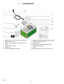
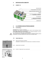
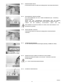
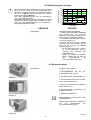
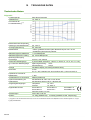
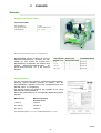
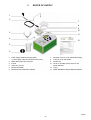
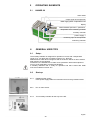
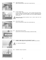
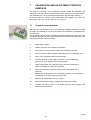
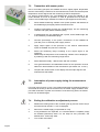
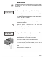
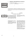
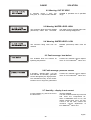
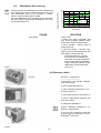
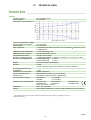
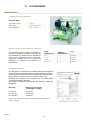
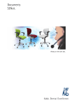
HUMOR 20 FEUCHTEKALIBRATOR HUMIDITY CALIBRATOR CALIBRATEUR D'HUMIDITÉ Bedienungsanleitung Hardware Manual Hardware Notice Matériel BA_HUMOR20_HW_01 // Technische Änderungen vorbehalten // 302251 HAFTUNGSEINSCHRÄNKUNG E+E Elektronik® haftet nicht für irgendwelche Schäden bzw. Folgeschäden (beispielsweise, aber nicht beschränkt auf Gewinn-Entgang, Geschäftsunterbrechung, Informations- und Datenverlust oder irgendwelchen anderen Vermögensschäden), die durch Installation, Verwendung und auch Unmöglichkeit der Verwendung eines Softwareprodukts von E+E Elektronik ® und eventuell damit zusammenhängenden Supportleistungen bzw. Nichtleistung von Support entstehen. E+E Elektronik® Ges.m.b.H. übernimmt für diese Publikation keinerlei Garantie und bei unsachgemäßer Handhabung der beschriebenen Produkte keinerlei Haftung. Diese Publikation kann technische Ungenauigkeiten oder typographische Fehler enthalten. Die hier enthaltenen Informationen werden regelmäßig überarbeitet. Diese Änderungen werden in späteren Ausgaben implementiert. Die beschriebenen Produkte können jederzeit verbessert oder geändet werden. Technische Änderungen vorbehalten. Copyright 2003 E+E Elektronik GmbH Alle Rechte vorbehalten. LIMITED LIABILITY E+E Elektronik® is not liable for any damages or consequential damages (for example, but not restricted to loss of earnings, interruption of business, loss of information and data or any other pecuniary damages), that result from the installation, usage and also impossibility of usage of a software product from E+E Elektronik® and support services possibly associated with it or non-performance of support. E+E ELEKTRONIK® Ges.m.b.H. takes no guarantee and liability neither upon this publication nor in case of improper treatment of the describted products. The document may contain technical inaccuracy and typographic errors. The content information will be revised steadily. These changes will be implemented in later versions. The described products can be improved and changed at any time. Technical data are subject to change. Copyright 2003 E+E Elektronik GmbH All rights reserved. RESPONSABILITE LIMITEE E+E Elektronik® décline toute responsabilité en cas de dommages consécutifs ou autres (par exemple, mais sans exhaustivité aucune, en cas de perte de revenus, d'interruption d'activité, de perte d'information et de données ou de tout autre dommage financier), résultant de l'installation, de l'utilisation et également d'une impossibilité d'utilisation d'un logiciel de E+E Elektronik® et des services de support qui y sont possiblement liés ainsi que de la non exécution du support. E+E ELEKTRONIK ® Ges.m.b.H. ne garantit et ne peut pas être tenu responsable du contenu de cette publication ainsi que de l'utilisation incorrecte des produits décrits. Le document peut contenir des imprécisions techniques ou des erreurs typographiques. Les informations contenues seront révisées immédiatement. Ces modifications seront implémentées dans les versions futures. Les produits décrits peuvent être améliorés et modifiés à tout moment. Les caractéristiques techniques sont sujettes à changement. Copyright 2003 E+E Elektronik GmbH Tous droits réservés. 2 INHALTSVERZEICHNIS HARDWARE 1 VORWORT 4 2 EG KONFORMITÄTSERKLÄRUNG 5 3 LIEFERUMFANG 6 4 SICHERHEITSHINWEISE 7 4.1 Allgemein 4.2 HUMOR 20 7 7 BEDIENUNGSELEMENTE 8 5.1 HUMOR 20 8 ALLGEMEINE BENUTZERHINWEISE 8 6.1 Aufstellung 6.2 Inbetriebnahme 8 8 5 6 7 8 KALIBRIER- UND JUSTIERVORGANG HUMOR 20 10 7.1 7.2 7.3 7.4 10 11 11 11 Kubische Transmitter (Raumausführung) Messumformer mit Stabfühler Unterbrechung der Energie- Versorgung während des Messvorgangs Beenden des Kalibrier- bzw. Justiervorganges WARTUNG 12 8.1 Wasser nachfüllen (bei Störmeldung: Water - Level low) 12 8.2 Wasser entleeren (bei Störmeldung: Water - Level high oder längere Standzeiten) 12 9 WARNUNGEN / FEHLERMELDUNGEN AM DISPLAY 13 9.1 9.2 9.3 9.4 9.5 9.6 9.7 9.8 9.9 13 14 14 14 14 14 14 15 15 Feuchte - Anzeige blinkt Warnung: out of spec Warnung: Waterlevel high Warnung: Waterlevel low Störmeldung: heat defekt Störmeldung: pressure excess Feuchte - Anzeige ist nicht korrekt Stabilisierungszeit zu lange Elektronik defekt - Austausch der Elektronik 10 TECHNISCHE DATEN 16 11 ZUBEHÖR 17 deutsch 3 1 VORWORT Die Firma E+E Elektronik® Ges.m.b.H. hat dieses Gerät zur präzisen Darstellung der relativen Luftfeuchte (Uw) entwickelt. Sie sind hiermit Besitzer eines professionellen Instrumentes zur hochgenauen Darstellung dieser physikalischen Größe in dessen Entwicklung, Konstruktion und Produktion der Hersteller sein gesamtes gegenwärtiges Wissen investiert hat. Der Hersteller ist weiters überzeugt, dass der Feuchte - Kalibrator HUMOR 20 sämtlichen Anforderungen und Erwartungen entspricht, welche Sie als Käufer mit der Neuanschaffung verbunden haben. Bei sachgemäßer Handhabung und regelmäßiger Wartung sollte das Gerät über Jahre zuverlässig arbeiten. Die Bedienungsanleitung ist Bestandteil des Lieferumfanges und dient der Sicherstellung einer sachgemäßen Handhabung und optimalen Funktion des Gerätes. Aus diesem Grund muss die Bedienungsanleitung unbedingt vor Inbetriebnahme gelesen werden. Darüber hinaus ist die Bedienungsanleitung jeglichen Personen, welche mit dem Transport, der Aufstellung, dem Betrieb, der Wartung und Reparatur befaßt sind in Kenntnis zu bringen. Diese Bedienungsanleitung darf nicht ohne unser schriftliches Einverständnis zu Zwecken des Wettbewerbes verwendet und auch nicht an Dritte weitergeleitet werden. Kopien für den Eigenbedarf sind erlaubt. Sämtliche in dieser Anleitung enthaltenen Informationen, technische Daten und Darstellungen basieren auf zum Zeitpunkt der Erstellung verfügbaren Informationen. Die Firma E+E Elektronik® Ges.m.b.H. behält sich das Recht vor, jederzeit und ohne Vorankündigung, Änderungen an den technischen Daten oder andere technische Modifikationen vorzunehmen, ohne eine Verpflichtung zu übernehmen, Modelle welche vor dem Datum einer solchen Änderung gefertigt wurden, nachzurüsten. Allgemein Diese Bedienungsanleitung stellt einen Bestandteil des Lieferumfanges dar und dient zur Sicherstellung einer optimalen Bedienung und Funktion des Gerätes. Um die einwandfreie Funktion zu gewährleisten, muss vor Inbetriebnahme diese Bedienungsanleitung genau gelesen werden. Symbolerklärung Dieses Zeichen zeigt Sicherheitshinweise an. Diese Sicherheitshinweise sind unbedingt zu befolgen. Bei Zuwiderhandlungen haftet der Hersteller nicht. Das Risiko trägt allein der Anwender. i Dieses Zeichen zeigt einen Hinweis an. Um eine optimale Funktion des Gerätes zu erreichen, sind diese Hinweise einzuhalten. deutsch 4 2 EG KONFORMITÄTSERKLÄRUNG Der Hersteller erklärt, dass das nachfolgend bezeichnete Gerät aufgrund seiner Konzipierung und Bauart, sowie in der von ihm in Verkehr gebrachten Ausführung den einschlägigen grundlegenden Sicherheits- und Gesundheitsanforderungen der EG-Richtlinien entspricht. Bei einer nicht mit dem Hersteller abgestimmten Änderung am Gerät, verliert diese Erklärung ihre Gültigkeit. Hersteller E+E Elektronik® Ges.m.b.H. Langwiesen 7 A-4209 Engerwitzdorf Tel.: ++43 / 7235 / 605-0 Fax: ++43 / 7235 / 605-8 [email protected] www.epluse.at Bezeichnung des Gerätes HUMOR 20 Der HUMOR 20 ist ein professionelles Gerät, welches eine relative Luftfeuchte darstellt, die dem Überprüfen (Kalibrieren, Justieren) von Feuchte - Messgeräten dient. Das Gerät entspricht der EG-Richtlinie Elektromagnetische Verträglichkeit (89/336/EEC) EG-Richtlinie Niederspannung (73/23/EEC) Angewandte harmonisierte Norm EN 61000-6-3 EN 61000-6-4 EN 61000-6-2 EN 61326-1 +A1 +A2 EN 61010-1 deutsch 5 3 LIEFERUMFANG 1 2 7 8 9 10 3 11 4 12 5 6 1 2 3 4 5 6 Netzkabel IEC Europe (230V) + Netzkabel IEC Nordamerika (110V) Wasser - Ablaufschlauch mit Anschlussstück Trichter Inbusschlüssel (10mm) Messbecher Mess- und Kalibrationssoftware 7 8 9 10 Plexiglas-Abdeckung für Raumtransmitter-Prüfung O-Ring für Raumtransmitter Rändelmuttern Abdeckung für Feuchtefühler mit 12mm Fühlerrohrdurchmesser 11 O-Ring 12 Werksprüfzeugnis nach DIN EN 10204-2.3 deutsch 6 4 SICHERHEITSHINWEISE 4.1 Allgemein Das Gerät HUMOR 20 ist nach dem heutigen Stand der Technik gebaut und somit in einwandfreiem Zustand und bei sachgemäßer Bedienung und Wartung betriebssicher. Von dem Gerät können Gefahren ausgehen, sofern es von unqualifiziertem Personal unsachgemäß oder nicht bestimmungsgemäß eingesetzt wird! • Schaden an dem Gerät selbst, an weiteren Vermögenswerten des Anwenders sowie am Bedienpersonal entstehen. • eine effiziente und genaue Arbeit des Gerätes verhindert werden. Dadurch kann: Im Sinne der eigenen Sicherheit sind nachstehende Hinweise besonders zu beachten: • Nur qualifiziertes oder besonders geschultes Personal darf mit der Bedienung oder mit Arbeiten an dem Feuchtekalibrator beauftragt werden. Eigenmächtige Veränderungen bzw. Modifikationen am Gerät sind nicht gestattet oder bedürfen einer ausdrücklichen Genehmigung des Herstellers. • Lesen Sie vor Inbetriebnahme des Gerätes die Bedienungsanleitung sorgfältig durch. Weiters muss die mitgelieferte Bedienungsanleitung jeglichen Personen, welche mit dem Transport, der Aufstellung, der Inbetriebnahme sowie der Bedienung und Wartung befasst sind, stets zugänglich gemacht werden. (Achtung bei Entlehnung oder Veräußerung des Gerätes an Dritte) • Das Gerät darf nur in einwandfreiem Zustand betrieben werden. Eventuell festgestellte Mängel müssen vor einer neuerlichen Inbetriebnahme entweder von autorisierten Personen, bzw. vom Kundendienst der Firma E+E Elektronik® Ges.m.b.H behoben werden. 4.2 HUMOR 20 • Prüfen Sie, ob die Angabe der Versorgungsspannung am Typenschild mit der örtlichen Netzspannung übereinstimmt. • Versorgen Sie den Feuchtekalibrator nur über eine Schutzkontakt - Steckdose (Schutzmaßnahme). • Bevor der Wassereinlass geöffnet wird ist sicherzustellen, dass der Feuchtelkalibrator nicht mehr unter Druck steht. (Regler ganz nach links gedreht, falls HUMOR schon in Betrieb Anzeige RH > 90%) • Der HUMOR darf ausschließlich mit destilliertem (de - ionisiertem) Wasser betrieben werden. • Vor dem Anschließen der Druckluft ist sicherzustellen, dass der Regler ganz nach links gedreht ist. • Das Gerät darf ausschließlich mit gefilterter Druckluft betrieben werden maximaler Verschmutzungsgrad <0,03g/m³. • Die Medienversorgung darf einen Absolutdruck von max. 10 bar nicht übersteigen. (Manometer und Sicherheitsventil in der Versorgungsleitung) • Der betriebsbereite, mit Wasser gefüllte Feuchtekalibrator darf beim Transport nicht mehr als 20° geneigt werden ! Ansonsten HUMOR 20 komplett entleeren --> Seite 12 : Kapitel 8.2 • Nach dem Abschalten muss der HUMOR von der Druckluft getrennt werden (mögliche Kondensation in den Leitungen wegen ausgeschalteter Heizung). deutsch 7 5 BEDIENUNGSELEMENTE 5.1 HUMOR 20 Wassereinlass Ausgangssignal des Prüflings Medienversorgung (Druckluft / N2) Display Umschalter Prüfling 1, Prüfling 2, Messkammertemperatur Feuchteregler Spannungsversorgung + Messeingänge der Prüflinge Messkammer 6 ALLGEMEINE BENUTZERHINWEISE 6.1 Aufstellung: Betriebsbereich: 10...40°C / 10...80% rF. Messungen unter direkter Sonneneinstrahlung sowie unter Einwirkung anderer externer Wärmequellen sind nicht zulässig. Der HUMOR 20 darf nicht in explosionsgefährdeten Bereichen betrieben, noch starken mechanischen Erschütterungen ausgesetzt werden. Wird der HUMOR 20 in betriebsbereitem Zustand (mit destilliertem Wasser gefüllt) transportiert, so darf das Gehäuse nicht mehr als 20° geneigt werden! 6.2 Inbetriebnahme: 6.2.1 Spannungsversorgung herstellen. Netzkabel am Gerät und an der Schutzkontakt - Steckdose einstecken. 6.2.2 Hauptschalter einschalten. 6.2.3 Feuchte - Regler ganz nach links drehen. deutsch 8 6.2.4 Wasserbehälter öffnen. Verschlussschraube mit Hilfe des beiliegenden Inbusschlüssels öffnen. 6.2.5 Mit destilliertem Wasser befüllen. Den Feuchtekalibrator mit max. 1300ml. destilliertem (de - ionisierten) Wasser befüllen. Wurde die max. Einfüllmenge überschritten wird am Display Water - Level high angezeigt und es muss wiederum Wasser entleert werden bis die Meldung verschwindet. (siehe Pkt. 8.2) Beim Befüllen ist besonders darauf zu achten, dass kein Wasser in die Messkammer gelangt. 6.2.6 Wasserbehälter schließen. Verschlussschraube mit Hilfe des beiliegenden Imbusschlüssels schließen. 6.2.7 Aufwärmphase abwarten. 20 min Aufwärmphase berücksichtigen (Display: WARM UP TIME). 6.2.8 Medienversorgung (ölfreie Druckluft od. N2) herstellen. Medienversorgung herstellen und Feuchte - Generator mit Druck beaufschlagen. ( p < 10 bar siehe Sicherheitshinweise) 6.2.9 HUMOR ist betriebsbereit. deutsch 9 7 KALIBRIER- UND JUSTIERVORGANG HUMOR 20 Die spezielle Konstruktion der Messkammer erlaubt die Kalibration und Justierung von Messwertgebern unterschiedlichster Bauformen. Von Stabfühlern mit einem Durchmesser von 8 - 25,5 mm (Handmessgeräte, Kanalbauformern,...) und von Raumtransmittern, Datenloggern, etc.. mit den maximalen Abmessungen 100 x 85 x 40 mm bzw. 95 x 95 x 40 mm. 7.1 Kubische Transmitter (Raumausführung) Unter Verwendung der im Lieferumfang enthaltenen Plexiglasabdeckung der Messkammer kann der HUMOR 20 auch für die Kalibration und Justage von Raumgeräten verwendet werden. Auf Grund der thermischen Einkopplungen von außen, ist in Abhängigkeit von der eingestellten Feuchte und Lage des Prüflings in der Messkammer mit zusätzichen Messfehlern zu rechnen. (siehe Datenblatt) 1. Versorgungsspannung anlegen. 2. Prüfling in der Messkammer positionieren. 3. O-Ring in vorgesehene Nut der Messkammer einlegen. 4. Anschlusskabel durch die PG Verschraubung des Plexiglasdeckel durchführen. 5. Deckel auflegen und beide Rändelmuttern fest anziehen. 6. Prüfling an die Versorgungsanschlüsse des HUMOR 20 (24VDC) anschließen. 7. Ausgangssignal des Prüflings an die internen Messeingänge des HUMOR 20 (Unit1 RH, Unit2 RH) anlegen. 8. Messbereich(e) entsprechend dem Ausgangssignal des (der) Prüflinge wählen. Zusätzlich kann durch ein Anwählen am Messbereichsumschalter die Temperatur der Messkammer am Display angezeigt werden. 9. Stabilisierungszeit abwarten (ca. 20min.) 10. Mit dem Regler den gewünschten Feuchte - Sollwert wählen. 11. Die am Display angezeigten Werte mit dem Ausgangssignal des Messumformers vergleichen. deutsch 10 7.2 Messumformer mit Stabfühler: Der HUMOR 20 hat auf Grund seines Funktionsprinzips eine geringfügig höhere Temperatur als die Umgebung. Bei der Vermessung ist daher darauf zu achten, dass sich die Fühlertemperatur an die Messkammertemperatur angleichen kann. Für präzise Vermessungen sollte die Deckeldurchführung weitestgehend dem Fühlerdurchmesser angepasst werden. Um dies zu gewährleisten stehen verschiedene Deckelausführungen zur Auswahl (siehe Anhang Zubehör). 1. Geeignete Messkammerabdeckung (Position und Durchmesser der Durchführung beachten) auflegen und beide Rändelmuttern festziehen. 2. Prüfling(e) durch die Durchführung(en) in die Messkammer einbringen und Verschraubung(en) festziehen. 3. Falls Durchführungen nicht mit einem Fühler bestückt werden, sind diese durch die mitgelieferten Blindstoppeln abzudichten. 4. Prüfling(e) an die Versorgungsanschlüsse des HUMOR 20 (24VDC) anschließen. 5. Ausgangssignal der Prüfling(e) an die internen Messeingänge des HUMOR 20 (Unit1 RH, Unit2 RH) anlegen. 6. Messbereich(e) entsprechend dem Ausgangssignal des (der) Prüflinge wählen. Zusätzlich kann durch ein Anwählen am Messbereichsumschalter die Temperatur der Messkammer am Display angezeigt werden. 7. Mit dem Regler den gewünschten Feuchte - Sollwert wählen. 8. Die üblichen Abweichungen und Stabilisierungszeiten des Prüflings müssen aus den Herstellerunterlagen entnommen werden (empfohlen werden jedoch mind. 15 min.). 9. Die am Display angezeigten Werte mit dem Ausgangssignal des Messumformers vergleichen. 7.3 Unterbrechung der Energie - Versorgung während des Messvorganges Bei längeren Energieausfällen (> 5min.) muss der Drehkopf des Reglers entsichert (hochziehen) und bis zum Anschlag nach links gedreht werden. Weiters sollte die Medienversorgung abgeklemmt werden. Nach Spannungswiederkehr und Ablauf der Aufwärmphase kann mit der Messung erneut begonnen werden. 7.4 Beenden des Kalibrier- bzw. Justiervorganges 1. Drehkopf des Reglers entsichern (hochziehen) und bis auf Anschlag nach links drehen und abwarten bis RH >= 90% angezeigt wird. 2. Entfernen der Medienversorgung (Druckluft / N2). 3. Bei voraussichtlich längeren Standzeiten empfiehlt sich, das destillierte (de - ionisierte) Wasser vollständig zu entleeren. Vorgehensweise siehe Wartung - Wasser entleeren. 4. Hauptschalter ausschalten (gegebenenfalls Schuko - Stecker ziehen). deutsch 11 8 i i WARTUNG Das destillierte (de - ionisierte) Wasser sollte periodisch alle 8 Wochen gewechselt werden. Wird das Gerät für längere Zeit nicht verwendet, wird empfohlen das Wasser vollständig zu entleeren. 8.1 Wasser nachfüllen (bei Störmeldung: Water - Level low) 1. Feuchte - Regler ganz nach links drehen und abwarten bis Anzeige “OUT OF SPEC” erscheint. 2. Verschlussschraube öffnen. 3. Destilliertes (de - ionisiertes) Wasser nachfüllen (bei Anzeige Water - Level low dürfen max. 1000ml nachgefüllt werden). 4. Verschlussschraube schließen. 5. Wurde die max. Einfüllmenge überschritten wird am Display Water - Level high angezeigt und es muss wiederum Wasser entleert werden bis die Störmeldung am Display erlischt. 6. Nach Befüllung ca. 20min Stabilisierungszeit abwarten (je größer der Temperaturunterschied des deionisierten Wassers gegenüber dem Feuchtekalibrator ist, umso länger sollte die Stabilisierungszeit sein). 7. HUMOR ist betriebsbereit. 8.2 Wasser entleeren (bei Störmeldung Water - Level high, längeren Standzeiten oder zum Transport) 1. Feuchte - Regler ganz nach links drehen und abwarten bis rel.HUM high erscheint. 2. Wasser-Ablaufschlauch an Ablaufstutzen anschließen. 3. Feuchte - Regler langsam nach rechts drehen bis Wasser ausströmt. Anzeige a.) Solange bis Water - Level high verschwindet. b.) Solange bis die Sättigungskammer vollständig entleert ist. Um eine völlig trockene Kammer zu erreichen sollte man kurze Zeit Luft nachströmen lassen. 4. Zum Beenden des Ablass - Vorganges Feuchte - Regler wieder ganz nach links drehen. 5. Druckluft und Wasserablaufschlauch abschließen. 6. HUMOR kann nun ausgeschaltet werden. deutsch 12 9 WARNUNGEN / FEHLERMELDUNG AM DISPLAY 1. 2. Zeile: Anzeige Feuchte () oder Fehler () Zeile: Statuszeile () und beim HUMOR Istwert-Anzeige des Prüflings Ihr Feuchtekalibrator ist mit einem Selbstdiagnose - System ausgerüstet. Je nach Betriebszustand oder aufgetretenem Fehler gibt er unterschiedliche Betriebs- oder Störmeldungen aus, welche folgende Maßnahmen nach sich ziehen sollten: URSACHE ABHILFE 9.1 Feuchte - Anzeige blinkt 1. Nach einer sprunghaften Veränderung des Sollwertes hat die Messkammer den gewünschten Wert nicht sofort erreicht. Sobald die Differenz der in der Messkammer dargestellten relativen Feuchte und dem gewünschten Sollwert einen definierten Bereich übersteigt, beginnt die Anzeige zu blinken. Stabilisierungszeit abwarten (nach einigen Minuten, sollte die Anzeige von selbst zu blinken aufhören). 2. Wasser in der Messkammer oder in internen Leitungen. Wird meistens durch den Transport eines mit Wasser gefüllten HUMOR 20 oder durch den Anschluss der Druckluft bei nicht vollständig nach links gedrehten Feuchte -Regler verursacht. Auftrocknen der Messkammer mit einem saugfähigen Tuch. Wasser vollständig entleeren und längere Zeit Medium nachströmen lassen. Dies wird durch eine Sollwertvorgabe von 75% über den Feuchte - Regler erreicht. Während des Spülvorganges (Trocknung) blinkt das Display und zeigt Warnung WATER LEVEL LOW. Der Trocknungsprozess dauert ca. 48h und sollte durch einen Prüfling überwacht werden. Die Trocknung ist erfolgreich abgeschlossen, sobald der Prüfling eine Relative Feuchte von < 15% zeigt. Die Dauer dieses Trocknungsvorganges wird durch Verwendung von trockener Druckluft bzw. trockenem Stickstoff beschleunigt. deutsch 13 URSACHE ABHILFE 9.2 Warnung: OUT OF SPEC Ein Feuchte - Sollwert > 95%RH wurde vorgegeben, oder < 10% RH wurde gewählt. Gerät wird außerhalb des spezifizierten Bereichs betrieben. 9.3 Warnung: WATERLEVEL HIGH Die maximale Füllmenge mit destilliertem (de - ionisiertem) Wasser wurde überschritten. Es muss wiederum Wasser entleert werden bis die Störmeldung erlischt. 9.4 Warnung: WATERLEVEL LOW Die minimale Füllmenge wurde unterschritten. Es muss destilliertes (de - ionisiertes Wasser) nachgefüllt werden. 9.5 Störmeldung: heat defect Der HUMOR erreicht seine Betriebstemperatur nicht. Kontaktieren Sie den Kundendienst der E+E Elektronik® Ges.m.b.H. 9.6 Störmeldung: pressure excess Es wurde ein Feuchte - Sollwert < 8% RH gewählt. Durch den hohen Druck kann der Feuchtekalibrator Schaden genommen haben - Die angegebenen Genauigkeit der Messungen kann nicht mehr länger gewährleistet werden. Kontaktieren Sie den Kundendienst der E+E Elektronik® Ges.m.b.H. 9.7 Feuchte - Anzeige ist nicht korrekt Unkorrekte Anzeige, z.B. auf Grund eines Fehlers in der Elektronik. deutsch 14 Überprüfung des HUMOR. Drehen Sie den Regler ganz nach links und schließen Sie die Druckluft ab. Nach 2h Stabilisierungszeit sollte die Anzeige 100 ±2%RH anzeigen. Sollte dies nicht der Fall sein, kontaktieren Sie bitte den Kundendienst der E+E Elektronik® Ges.m.b.H. 9.8 Stabilisierungszeit zu lange relative Feuchte [%r.F.] i 100 Das Zeitverhalten des HUMOR 20 für Feuchtesprünge 25-80 %r.F. bzw. 80-25 %r.F. lässt sich aus dem Chart ablesen und liegt bei Sprüngen zu niedrigeren Werten bei etwa 1 Minute und bei Sprüngen zu höheren Feuchten bei etwa 3 Minuten. Die nötige Stabilisierungszeit wird im wesentlichen durch den Prüfling bestimmt. Unter Berücksichtigung der Ansprechzeiten am Markt befindlicher Fühler (ausgerüstet mit üblichen Filtern) sollte mit einer Stabilisierungszeit von 20 Minuten / Messpunkt gearbeitet werden. 90 80 70 60 25%...80% 50 80%...25% 40 30 20 0,0 1,0 2,0 3,0 4,0 5,0 Zeit [min] URSACHE ABHILFE Ventil defekt. Überprüfung des Durchflusses. 1. Entleeren Sie das Wasser vollständig und befüllen Sie den Feuchtekalibrator anschließend wiederum mit exakt 1000ml destilliertem Wasser. 2. Geben Sie einen Feuchte - Sollwert von genau 20%RH vor. 3. Drehen Sie den Feuchte - Regler ganz nach links und messen Sie die Zeit bis die Anzeige am Display 80%RH erreicht. - Ist die gemessene Zeit < 80sec. so ist der Durchfluss völlig in Ordnung und innerhalb des Arbeitsbereiches. - Dauert der Vorgang wesentlich länger wenden Sie sich bitte an den Kundendienst der E+E Elektronik® Ges.m.b.H. 9.9 Elektronik defekt Verschiedene Austausch der Elektronik: 1. Feuchtekalibrator von der sorgungsspannung trennen. Ver- 2. Schrauben öfffnen (siehe Abbildung 1). Abbildung 1 3. Kreuzschlitzschrauben am 19” Rack öffnen (siehe Abbildung 2). 4. Einschub (Elektronik) herausziehen (siehe Abbildung 3). 5. Ersatzelektronik einschieben und Gehäuse schließen. 6. Kalibration HUMOR 20. Abbildung 2 i Werkskalibration erlischt durch einen Elektroniktausch! Sollten Fragen auftreten, kontaktieren Sie den Kundendienst der E+E Elektronik® Ges.m.b.H. Abbildung 3 deutsch 15 10 TECHNISCHE DATEN Technische Daten Allgemein Zwei-Druck Generator 10...95% rF u(Uw) [% rF] (k=2) Funktionsprinzip Arbeitsbereich Unsicherheit der Feuchtedarstellung1) 2) relative Feuchte Uw [% rF] Messunsicherheit Temperaturmessung in der Messkammer2) Versorgungsspannung Betriebsmittel Stabilisierungszeit HUMOR 20 Stabilisierungszeit für Prüfling Spannungsversorgung für Prüflinge Anzahl der Messeingänge typ. Fehler der Messeingänge Anzeige Durchfluss empfohlenes Intervall für Rekalibration Schnittstelle für PC-Anschluss Systemvoraussetzung für Softwaretools Umgebungsbedingungen Angewandte Normen Abmessungen Gewicht typ. ±0,3°C 90...230V AC • ölfreie, gefilterte Druckluft (oder Stickstoff N2) mit max. 10 bar • destilliertes (deionisiertes) Wasser < 3 min/Messpunkt typ. 20 min/Messpunkt 24V DC, max. 200mA 2 (umschaltbar zwischen 4...20mA / 0...20mA / 0...1V / 0...5V / 0...10V) Spannungsmessung: < 5mV Strommessung: < 30µA Dot-Matrix Display mit Hintergrundbeleuchtung 3 l/min für rF > 85% reduziert sich der Durchfluss auf 1,5 l/min bei 95% rF 1 Jahr RS232 (COM-Port) MS Windows 98 / ME / NT 4.0 mit SP 6a MS Windows 2000 mit SP 2 / Windows XP Temperatur: 10...40°C Feuchte: 10...80% rF EN 61000-6-3 EN 61000-6-4 EN 60068-2-6 EN 61000-6-2 EN 61010-1 EN 60068-2-29 ÖVE EN 61326-1+A1+A2 400 x 260 x 240 mm ca. 23kg (HUMOR 20) ca.36,5kg (HUMOR 20 inkl. Verpackung) 1) Angegeben ist die erweiterte Messunsicherheit, die sich aus der Standardunsicherheit durch Multiplikation mit dem Erweiterungsfaktor K = 2 ergibt. 2) gültig für Metalldeckeln deutsch 16 11 ZUBEHÖR Zubehör Kompressor mit Ölabscheider Technische Daten Max: Arbeitsbereich 12 bar Versorgungsspannung 230V AC oder 115V AC Arbeitstemperatur -10 ... +70°C Messkammerabdeckungen für Stabfühler Standardmäßig wird der HUMOR 20 mit einer Messkammerabdeckung, geeignet für den Einbau von zwei Fühlern mit ∅12mm (E+E Standardfühler), ausgeliefert. Als Zubehör sind weitere Messkammerabdeckungen für Fühlerrohrdurchmesser von 8 bis 25,5mm erhältlich. FÜHLERDURCH- ANZAHL DER MESSER [mm] TYPENBEZEICHNUNG DURCHFÜHRUNGEN 8 - 12 3 HA 02 02 04 12 - 16 2 HA 02 02 01 16 - 20,5 1 HA 02 02 02 20,5 - 25,5 1 HA 02 02 03 Kalibrierzertifikat Um den Anforderungen bezüglich protokollierter Messmittelüberwachung gemäß ISO9001 gerecht zu werden, wird der Feuchtekalibrator HUMOR 20 mit einem Werksprüfzeugnis nach DIN EN 10204 - 2.3 ausgeliefert. Als Zubehör bietet E+E Elektronik den HUMOR 20 mit einem akkreditierten ÖKD Zertifikat an. Diese ÖKD Akkreditierung ist mit folgenden Messunsicherheiten behaftet: Messbereich Messunsicherheit (bei 25°C ±3°C) < 35% rF ±0,2% rF 35...60% rF ±0,35% rF 60...95% rF ±0,5% rF (bei Taupunkttemperatur -10°C...60°C und Messtemperatur 0°C...70°C) deutsch 17 TABLE OF CONTENTS HARDWARE 1 FOREWORD 19 2 EG DECLARATION OF CONFORMITY 20 3 SCOPE OF SUPPLY 21 4 SAFETY INSTRUCTIONS 22 4.1 General 4.2 HUMOR 20 22 22 OPERATING ELEMENTS 23 5.1 HUMOR 20 23 GENERAL USER TIPS 23 5 6 6.1 Setup 6.2 Start-up 23 23 7 CALIBRATION AND ADJUSTMENT PROCESS HUMOR 20 25 7.1 Compact room transmitter 7.2 Transmitter with sensor probe 7.3 Interruption of power supply during the measurement process 7.4 Ending the calibration or adjustment process 25 26 26 26 MAINTENANCE 27 8.1 Adding water (for fault message: Water - Level low) 8.2 Removing water (for fault message: Water - Level high or long downtimes) 27 27 WARNINGS / ERROR MESSAGES ON THE DIPLAY 28 9.1 9.2 9.3 9.4 9.5 9.6 9.7 9.8 9.9 28 29 29 29 29 29 29 30 30 8 9 Humidity - display blinks Warning: out of spec Warning: Waterlevel high Warning: Waterlevel low Fault message: heat defect Fault message: pressure excess Humidity - display is not correct Stabilization time too long Electronic defect - electronic replacement 10 TECHNICAL DATA 31 11 ACCESSORIES 32 english 18 1 FOREWORD E+E Elektronik® Ges.m.b.H. has developed this instrument for the precise description of the relative air humidity (Uw). You are now the owner of a professional instrument for high-quality representation of the physical parameters mentioned above. The manufacturer has invested its entire current knowledge into the development, construction, and productionof this instrument. Furthermore, the manufacturer is convinced that the humidity calibrator HUMOR 20 meets all requirements and expectations that you might have as the buyer of a new instrument. With proper handling and regular maintenance, the instrument should operate reliably for many years. The Manual is a part of the scope of supply and serve for guaranteeing proper handling and optimum functioning of the instrument. For this reason, the Manual must be read before start-up. In addition, the operating instructions are for all personnel who require knowledge concerning transport, setup, operation, maintenance, and repair. These operating instructions should not be used for the purpose of competition without our written consent and should also not be forwarded to third parties. Copies for your own personal use are permitted. All information, technical data, and illustrations contained in these instructions are based on information available at the time of publication. E+E Elektronik® Ges.m.b.H. maintains the right to change the technical data or make other technical modifications at any time and without prior announcement, without being obligated to retrofit models that were manufactured before the date of such a change. General These operating instructions represent a part of the scope of supply and serve for guaranteeing optimum operation and functioning of the instrument. In order to guarantee problem-free functioning, these operating instruction must be read very carefully before start-up. Explanation of symbols This symbol indicates a safety tip. These safety tips must be observed. The manufacturer is not responsible for violations of these tips. The user alone bears the full risk. i This symbol indicates a tip. In order to achieve optimum function of the instrument, these tips are to be observed. english 19 2 EG DECLARATION OF CONFORMITY The manufacturer declares that the instrument designated below corresponds to the relevant basic safety and health requirements of the EG guidelines in terms of its design and construction, as well as in the configuration put into circulation by the manufacturer. If the instrument is changed without the consent of the manufacturer, this declaration is no longer valid. Manufacturer E+E Elektronik® Ges.m.b.H. Langwiesen 7 A-4209 Engerwitzdorf Austria Tel.: ++43 / 7235 / 605-0 Fax: ++43 / 7235 / 605-8 [email protected] www.epluse.net Designation of the Instrument HUMOR 20 The HUMOR 20 is a professional instrument that describes relative air humidity used to test (calibrate, adjust) humidity instruments. The instrument corresponds to EG guideline Electromagnetic Compatibility (89/336/EWG) EG guideline Low Voltage (73/23/EWG) Applied harmonized standards EN 61000-6-3 EN 61000-6-4 EN 61000-6-2 EN 61326-1 +A1 +A2 EN 61010-1 english 20 3 SCOPE OF SUPPLY 1 2 7 8 9 10 3 11 4 12 5 6 1 2 3 4 5 6 7 8 9 10 Power supply cable IEC Europe (230V) + power supply cable IEC Northamerica (110V) Water drain pipe with connector Funnel Allen key (10 mm) Measuring beaker Measuring and calibration software 11 12 Plexiglas cover for room transmitter testing O-ring for room transmitter Knurled nut Cover for humidity sensor with 12 mm probe diameter O-ring Works certificate according to DIN EN 10204-2.3 english 21 4 SAFETY INSTRUCTIONS 4.1 General The instrument HUMOR 20 is built according to the current state of the art and it will operate reliably if it is free from faults and if it is properly operated and maintained. The instrument can present a risk if it is used improperly or not according to specifications by unqualified personnel! This can result in: • damage to the instrument itself, to other assets of the user, as well as to the operating personnel. • inefficient and imprecise operation of the instrument. For the sake of your own safety, the following tips in particular are to be observed: • Only qualified or specially trained personnel should be tasked with operating or working with the humidity calibrator. Unauthorized changes or modifications to the instrument are not permitted or require the express authorization of the manufacturer. • Carefully read through the operating instructions before starting up the instrument. Furthermore, the supplied operating instructions must always be accessible to all personnel concerned with the transport, setup, start-up, operation, and maintenance. (Be very careful when lending or disposing of the instrument to third parties) • The instrument should only be operated in a fault-free state. Possible defects must be repaired either by authorized persons or by the customer service department of E+E Elektronik® Ges.m.b.H before starting up the instrument. 4.2 HUMOR 20 • Check whether the details for the supply voltage on the nameplate agree with the local mains supply. • Only use a grounded plug to connect the humidity calibrator to power (protective measures). • Before opening the water inlet, guarantee that the humidity calibrator is no longer under pressure. (Controller turned all the way to the left, if HUMOR is already in operation, display RH > 90% ) • The HUMOR should only be operated with distilled (deionized) water. • Before connecting the compressed air, guarantee that the controller is turned all the way to the left. • The instrument should only be operated with filtered compressed air maximum contamination level < 0.03 g/m³. • The media supply should not exceed an absolute pressure of max. 10 bar. (Manometer and safety valve in the supply line) • A humidity calibrator that is ready for operation and that is filled with water must not be tilted more than 20 degrees ! Otherwise empty HUMOR 20 totally --> page 27 : chapter 8.2 • Disconnect compressed air after power off (running risk of condensation in the pipes because of switched off heating). english 22 5 OPERATING ELEMENTS 5.1 HUMOR 20 water intake output signal of the specimen media supply (oil-free compressed air / N2 display switch between specimen 1, specimen 2, temperature of the measuring chamber humidity controller powers supply + measuring input of the specimen measuring chamber 6 GENERAL USER TIPS 6.1 Setup: The humidity calibrator is designed for operation in rooms with a temperature range of 10...40 degC and a humidity content of 10...80% RH. Measurements under direct sunlight as well as under the effects of other external heat sources are not allowed. Furthermore, the HUMOR 20 is neither to be operated in areas with explosives nor is it to be subjected to mechanical vibrations. A humidity calibrator that is ready for operation and that is filled with water must not be tilted more than 20°! 6.2 Start-up: 6.2.1 Establish power supply. Insert power supply cable into instrument and into the grounded socket. 6.2.2 Turn on main switch. 6.2.3 Turn humidity controller all the way to the left. english 23 6.2.4 Open water container. Open screw plug with the help of the included Allen key. 6.2.5 Fill with distilled water. Fill the humidity calibrator with max. 1300 ml distilled (deionized) water. If the max. fill lever is exceeded, Water - Level high is displayed on the display and water must be removed until the message disappears. (see Item 8.2) During filling, pay special attention that no water enters into the measuring chamber. 6.2.6 Close water container. Close screw plug with the help of the included allen key. 6.2.7 Wait through warm-up phase. Observe 20 min warm-up phase (Display: WARM UP TIME). 6.2.8 Establish media supply (oil-free compressed air or N2). Establish media supply and charge humidity - generator with pressure. ( p < 10 bar see safety tips) 6.2.9 HUMOR is ready for operation. english 24 7 CALIBRATION AND ADJUSTMENT PROCESS HUMOR 20 The special construction of the measuring chamber allows the calibration and adjustment of a wide variety of measurement value sensors. From sensor probes with a diameter of 8 - 25.5 mm (hand-held instruments, duct mounting versions, ...) as well as those for compact (room) transmitters, data loggers, etc. with max. dimensions 100 x 85 x 40 mm resp. 95 x 95 x 40 mm. 7.1 Compact room transmitter With the use of the Plexiglas cover of the measuring chamber included in the scope of supply, the HUMOR 20 can also be used for the calibration and adjustment of room devices. Due to thermal coupling with the outside, additional measurement errors are to be considered depending on the used humidity and the position of the specimen in the measuring chamber. (see data sheet) 1. Apply supply voltage. 2. Position specimen in the measuring chamber. 3. Insert O-ring in the groove provided in the measuring chamber. 4. Pass connection cable through the threaded joint of the Plexiglas cover. 5. Place cover and fasten both knurled nuts tight. 6. Connect specimen to the supply connections of the HUMOR 20 (24V DC) or to an external power supply section. 7. Apply output signal of the specimen to the internal measurement inputs of HUMOR 20 (Unit1 RH, Unit2 RH). 8. Select the measuring range according to the output signal of the specimen. Additionally the temperture of the measuring chamber can be displayed by selecting it with the measuring range switch. 9. Wait through stabilization time (ca. 20 min.). 10. Select the desired humidity - desired value with the controller. 11. Compare the values shown on the display with the output signal of the measurement transmitter. english 25 7.2 Transmitter with sensor probe: Due to its working principle, the HUMOR 20 has a slightly higher temperature than the surroundings. Therefore, for the measurement, make sure that the probe temperature can be aligned with the measuring chamber temperature. For precise measurements, the cover-feedthrough should be adapted to the probe diameter as much as possible. In order to guarantee this fit, there are various cover-feedthroughs available for selection (see Appendix Accessories). 1. Place suitable measuring chamber cover (watch position and diameter of the feedthrough) and tightly fasten both knurled nuts. 2. Introduce specimen(s) through the feedthrough(s) into the measuring chamber and tightly fasten threaded joint(s). 3. If feedthroughs are not equipped with a probe, these feedthroughs are to be sealed by included blind plugs. 4. Connect specimen(s) to the power connections of the HUMOR 20 (24V DC) or to an external power supply section. 5. Apply output signal of the specimen to the internal measurement inputs of HUMOR 20 (Unit1 RH, Unit2 RH). 6. Select the measuring range according to the output signal of the specimen. Additionally the temperture of the measuring chamber can be displayed by selecting it with the measuring range switch. 7. Select desired humidity - desired value with the controller. 8. The typical deviations and stabilization times for the specimen must be taken from documentation of the manufacturer (we advise min. 15 min.). 9. Compare the values shown in the display with the output signal of the measurement transmitter. 7.3 Interruption of power supply during the measurement process For longer loss of power (>5 min.), the rotating head must be released (pulled up) and turned all the way to the left. Furthermore, the media supply should be clamped. After restoration of power and execution of the warm-up phase, the measurement can be started again. 7.4 Ending the calibration or adjustment process 1. Release the rotating head of the controller (pull up) and turn all the way to the left and wait until RH >= 90% is displayed. 2. Remove the media supply (compressed air / N2). 3. If long downtimes are expected, it is recommended to completely empty the distilled (deionized) water. For the steps for this procedure, see Maintenance - Removing water. 4. Turn off the main switch. english 26 8 i i MAINTENANCE The distilled (deionized) water should be changed periodically every 8 weeks. If the instrument is not used for long periods, it is recommended to completely remove the water. 8.1 Adding water (for fault message: Water - Level low) 1. Turn humidity - controller all the way to the left and wait until the display indicates “OUT OF SPEC”. 2. Open screw plug. 3. Fill with distilled (deionized) water (when the display indicates Water Level low, max. 1000 ml can be filled). 4. Close screw plug. 5. If the max. filling level is exceeded, the display indicates Water - Level high and water must be removed until the fault message disappears from the display. 6. After filling, wait for a stabilization time of ca. 20 min (the greater the temperature difference of the deionized water relative to the humidity - generator, the longer the stabilization time should be). 7. HUMOR is ready for operation. 8.2 Removing water (for fault message: Water - Level high, long downtimes or for transport) 1. Turn humidity - controller all the way to the left and wait for the display to show “rel.HUM high”. 2. Water drain pipe with connector to drain connection piece. 3. Turn humidity - controller slowly to the right until water flows out. a.) Until Water - Level high disappears. b.) Until the saturation chamber is completely empty. In order to achieve a totally dry chamber, let air flow through for a short time. 4. To end the drainage process turn the controller all the way to the left again. 5. Close compressed air and water drain pipe. 6. HUMOR can now be turned off. english 27 9 WARNINGS / ERROR MESSAGE ON THE DISPLAY 1. 2. Line: Display Humidity () or Error () Line: Status line () or at HUMOR 20 current measuring value of the selected specimen Your humidity calibrator is equipped with a self-diagnosis system. According to the operating state or the error that has occurred, different operating or fault messages are reported and these messages should be followed according to the following means: CAUSE SOLUTION 9.1 Humidity - Display blinks 1. After a rapid change of the desired value, the measuring chamber did not reach the desired value. As soon as the difference of the relative humidity described in the measuring chamber and the desired value exceeds a defined range, the display starts to blink. Wait through stabilization time (after some minutes, the display should stop blinking by itself). 2. Water in the measuring chamber or in the internal lines. Is usually caused by the transport of a HUMOR 20 filled with water or by the connection of the compressed air for a humidity - controller that is not turned all the way to the left. Dry the measuring chamber with an absorbent cloth. Empty water completely and let medium flow through for a long time. This is reached by a desired value setting of 75% on the humidity - controller. During the flushing process (drying), the display blinks and shows the warning WATER LEVEL LOW. The drying process lasts ca. 48h and should be monitored with a specimen. The drying is successfully completed as soon as the specimen shows a relative humidity of < 15%. The length of this drying process is accelerated by the use of dry compressed air or by the use of dry nitrogen. english 28 CAUSE SOLUTION 9.2 Warning: OUT OF SPEC A humidity range > 95% RH was given, or < 10% RH was selected. HUMOR is operated out of specified range. 9.3 Warning: WATER LEVEL HIGH The maximum filling level with distilled (deionized) water was exceeded. The water must be emptied again until the fault message disappears. 9.4 Warning: WATER LEVEL LOW The minimum filling level was not reached. Distilled (deionized) water must be filled. 9.5 Fault message: heat defect The HUMOR does not achieve its operating temperature. Contact the customer service department of E+E Elektronik® Ges.m.b.H. 9.6 Fault message: pressure excess A humidity - desired value < 8% RH was selected. The humidity - generator can be damaged by the high pressure. The indicated accuracy of the measurements can no longer be guaranteed. Contact the customer service department of E+E Elektronik® Ges.m.b.H. 9.7 Humidity - display is not correct Incorrect display, e.g. due to an error in the electronics. Test the HUMOR. Turn the controller all the way to the left and close the compressed air. After a stabilization time of 2h, the display should show 100 ± 2% RH. If this is not the case, contact the customer service department of E+E Elektronik® Ges.m.b.H. english 29 9.8 The chart shows the stabilisation time of the HUMOR 20 at a humidity step from 25 to 80% RH and 80 to 25% RH. The stabilisation time at low humidity is approx. 1 min., at high humidity approx. 3 min. The total stabilisation time is defined by the specimen. We recommend to allow a total stabilisation time of min. 20 min/measuring point. 100 90 Relative Humidity [% RH] i Stabilization time too long 80 70 60 25%...80% 50 80%...25% 40 30 20 0,0 1,0 2,0 3,0 4,0 5,0 Time [min] CAUSE SOLUTION Valve defect. Test the flow. 1. Empty the water completely and then fill the humidity calibrator again with exactly 1000 ml distilled water. 2. Set a humidity - desired value of exactly 20% RH. 3. Turn the humidity - controller completely to the left and measure the time until display reaches 80% RH. - If the measured time < 80 sec. then the flow is completely fine and within the range of operation. - If the process takes considerably longer, contact the customer service department of E+E Elektronik® Ges.m.b.H. picture 1 9.9 Electronic defect Several Electronic - replacement: 1. Disconnect the humidity calibrator from power supply. 2. Open screws (see picture 1). picture 2 3. Open recessed head screw on 19” rack (see picture 2). 4. Pull out the electronic (see picture 3). 5. Push in replacement electronic and close the housing. 6. Calibration HUMOR 20. picture 3 i Factory calibration disapears by an electronic replacement! If you have any questions contact the customer service department of E+E Elektronik® Ges.m.b.H. english 30 10 TECHNICAL DATA Technical Data General two-pressure-reactor 10...95% RH u(Uw) [% RH] (k=2) Function principle Working range Inaccuracy of measurement1) 2) relative humidity Uw [% RH] Inaccuracy temperature measurement in measuring chamber2) Power supply Work equipment Stabilisation time HUMOR 20 Stabilisation time specimen Integrated power supply Number of measuring inputs Typ. error for display inputs Display Gas flow Recommended interval for recalibration Interface for PC connection System requirements for software tools Environmental conditions Applied harmonised standards Dimensions Weight typ. ±0.3 degC 90...230V AC • compressed air, filtered and free of oil or nitrogen N2 with max. 10 bar • distilled water < 3 min/measuring point typ. 20 min/measuring point 24V DC, max. 200mA 2 (switchable between 4...20mA / 0...20mA / 0...1V / 0...5V / 0...10V) Voltage measuring: < 5mV Current measuring: < 30µA Dot-matrix display with backlight 3 l/min for RH > 85% the gas flow is reduced to 1.5 l/min at 95% RH 1 year RS232 (COM port) MS Windows 98 / ME / NT 4.0 with SP 6a MS Windows 2000 with SP 2 / Windows XP temperature: 10...40 degC humidity: 10...80% RH EN 61000-6-3 EN 61000-6-4 EN 60068-2-6 EN 61000-6-2 EN 61010-1 EN 60068-2-29 OEVE EN 61326-1+A1+A2 400 x 260 x 240 mm about 23kg (HUMOR 20) about 36.5kg (HUMOR 20 incl. packaging) 1) The extended inaccuracy of measurement results from the standard inaccuracy increased by a multiplying factor of K=2. 2) Valid for metall covers english 31 11 ACCESSORIES Accessories Compressor with oil seperator Technical data Max. operation pressure 12 bar Supply voltage 230V AC or 115V AC Working temperature -10 ... +70 degC Optional covers for the measuring chambers The standard scope of supply of HUMOR 20 includes a measuring chamber cover that can accommodate two sensors with a diameter of 12mm (E+E standard sensor). Additional measuring chamber covers for sensor tube diameters of 8-25.5mm are available as accessories. PROBE NUMBER OF DIAMETER [mm] FEEDTHROUGHS 8 - 12 3 HA 02 02 04 12 - 16 2 HA 02 02 01 16 - 20.5 1 HA 02 02 02 20.5 - 25.5 1 HA 02 02 03 Calibration certificate To meet with the requirements of Quality Management Systems such as ISO9001 regarding calibration and certification of measurement and test instrumentation, the HUMOR 20 is supplied with a factory works certificate according to DIN EN 10204 - 2.3. Optionally the HUMOR 20 is available with an official OEKD accredited calibration certificate. This OEKD accreditation guarantees the following measuring uncertainty: RH range Measuring uncertainty (at 25 degC ± 3 degC) < 35% RH ±0.2% RH 35...60% RH ±0.35% RH 60...95% RH ±0.5% RH TYPE (for dew point temperature -10 degC...60 degC and measuring temperature 0 degC...70 degC) english 32 TABLE DES MATIERES MATERIEL 1 AVANT PROPOS 34 2 DECLARATION DE CONFORMITE CE 35 3 ELEMENTS DE LA FOURNITURE 36 4 INSTRUCTIONS DE SECURITE 37 4.1 Généralités 4.2 HUMOR 20 37 37 ELEMENTS FONCTIONNELS 38 5.1 HUMOR 20 38 CONSEILS GENERAUX DESTINES A L'UTILISATEUR 38 6.1 Installation 6.2 Mise en marche 38 38 PROCEDURES DE CALIBRATION ET D'AJUSTEMENT DU HUMOR 20 40 5 6 7 7.1 Transmetteur compact de laboratoire 40 7.2 Transmetteur avec sonde 41 7.3 Coupure de l'alimentation électrique durant le processus de calibration 41 7.4 Achèvement de la procédure de calibration ou d'ajustement 41 8 MAINTENANCE 42 8.1 Ajout d'eau (en cas de message d'erreur : Eau - Niveau bas) 8.2 Enlèvement d'eau (en cas de message d'erreur : Eau - Niveau haut ou temps d'arrêt) 42 MESSAGES D'AVERTISSEMENT / D'ERREUR A L'ECRAN 43 9.1 Humidité - affichage clignotant 9.2 Attention : hors plage (out of spec.) 9.3 Attention : niveau d'eau élevé (Water Level High) 9.4 Attention : niveau d'eau bas (Water Level Low) 9.5 Message d'erreur : défaut chauffe (heat defect) 9.6 Message d'erreur : pression excessive (pressure excess) 9.7 Humidité - affichage incorrect 9.8 Temps de stabilisation trop long 9.9 Défaut électronique - remplacement du composant électronique 43 44 44 44 44 44 44 45 45 10 CARACTERISTIQUES TECHNIQUES 46 11 ACCESSOIRES 47 9 42 français 33 1 AVANT PROPOS E+E Elektronik® Ges.m.b.H. a développé cet instrument pour la génération précise de l'humidité relative de l'air (Uw). Vous êtes maintenant en possession d'un instrument professionnel destiné à la représentation de haute qualité des paramètres physiques mentionnés ci-dessus. Le fabricant a investi toutes ses connaissances actuelles dans le développement, la construction et la production de cet instrument. En outre, le fabricant est convaincu que le générateur d'humidité HUMOR 20 satisfait tous les besoins et toutes les attentes que vous pouvez manifester en tant qu'acheteur d'un nouvel instrument. L'instrument devrait fonctionner de manière fiable durant de nombreuses années grâce à une manipulation correcte et un entretien régulier. La Notice fait partie intégrante du cadre de la fourniture et sert à garantir la manipulation correcte et le fonctionnement optimum de l'instrument. Pour cette raison, la Notice doit être lue avant toute mise en marche. En outre, les instructions de service sont destinées à toutes les personnes souhaitant obtenir plus d'informations en termes de transport, d'installation, d'utilisation, de maintenance et de réparation. Ces instructions de service ne devront pas être utilisées dans un but de mise en concurrence sans notre consentement écrit et ne devront également pas être transmises à un tiers. Des copies destinées à votre propre personnel sont autorisées. Toutes les informations, caractéristiques techniques et illustrations contenues dans ces instructions sont basées sur les informations disponibles au moment de la publication. E+E Elektronik® Ges.m.b.H. se réserve le droit de modifier les caractéristiques techniques, ou de réaliser d'autres modifications d'ordre technique à tout moment et sans préavis ainsi que sans être obligé de moderniser les modèles fabriqués avant la date de la dite modification. Généralités Ces instructions de service représentent une partie intégrante du cadre de la fourniture et servent à garantir l'utilisation et le fonctionnement optimal de l'appareil. Ces instructions de service doivent être lues très attentivement avant la mise en marche de manière à garantir un fonctionnement sans panne. Explication des symboles Ce symbole indique un conseil de sécurité. Ces conseils de sécurité doivent être observés. Le fabricant n'est pas responsable en cas de violation de ces conseils. L'utilisateur est le seul à supporter tous les risques. i Ce symbole indique un conseil Ces conseils doivent être respectés afin d'obtenir le fonctionnement optimum de l'appareil. français 34 2 DECLARATION DE CONFORMITE CE Le fabricant déclare que l'instrument désigné ci-dessous correspond aux exigences de sécurité et de santé de base, relatives aux instructions CE en termes de conception et de construction, ainsi que dans la configuration mise en circulation par le fabricant. Cette déclaration sera déclarée caduque et non avenue en cas de modification de l'instrument accord préalable du fabricant. Fabricant E+E Elektronik® Ges.m.b.H. Langwiesen 7 A-4209 Engerwitzdorf Austria Tel.: ++43 / 7235 / 605-0 Fax: ++43 / 7235 / 605-8 [email protected] www.epluse.net Désignation de l'appareil HUMOR 20 Le HUMOR 20 est un instrument professionnel pour la génération de l'humidité relative de l'air utilisé pour étalonner (calibrer, régler) les instruments de mesure d'humidité. L'instrument correspond à : Instruction EG relative à la Compatibilité électromagnétique (89/336/EWG) Instruction EG relative aux applications basse tension (73/23/EWG) Normes harmonisées appliquées EN 61000-6-3 EN 61000-6-4 EN 61000-6-2 EN 61326-1 +A1 +A2 EN 61010-1 français 35 3 ELEMENTS DE LA FOURNITURE 1 2 7 8 9 10 3 11 4 12 5 6 1 2 3 4 5 6 Câble d'alimentation électrique normalisé IEC Europe (230V) + câble d'alimentation électrique normalisé IEC Amérique du Nord (110V) Conduite de purge d'eau avec raccord Entonnoir Clé Allen (10 mm) Bécher gradué Logiciel de mesure et de calibration 7 8 9 10 11 12 français 36 Couvercle en plexiglas pour le test du transmetteur de laboratoire Joint torique pour le transmetteur de laboratoire Ecrou moleté Couvercle pour capteur d'humidité avec joint torique pour diamètre de sonde de 12mm Joint torique Certificat de conformité selon la norme DIN EN 10204-2.3 4 INSTRUCTIONS DE SECURITE 4.1 Généralités L'instrument HUMOR 20 est construit conformément aux règles de l'art actuelles. Il fonctionnera de manière fiable à condition d'être utilisé et entretenu correctement. L'instrument peut présenter un risque en cas d'utilisation incorrecte ou non conforme aux spécifications par du personnel insuffisamment qualifié ! • l'endommagement de l'instrument lui-même, des autres biens de l'utilisateur ainsi qu'un risque de blessure du personnel de service. • un fonctionnement inefficace et imprécis de l'instrument. Cela peut entraîner : Les conseils suivants doivent être particulièrement observés pour votre propre sécurité : • Seul le personnel qualifié ou spécialement formé devra être chargé d'utiliser ou de travailler avec le générateur d'humidité. Tout changement ou toute modification non autorisée de l'instrument est interdite ou nécessite l'autorisation préalable du fabricant. • Lire précautionneusement toutes les instructions de service avant de mettre l'instrument en marche. De plus, les instructions de service fournies doivent tou jours être accessibles à tout le personnel concerné par le transport, l'installation, la mise en marche, l'utilisation et l'entretien. (Faire très attention en cas de prêt ou de lègue de l'instrument à un tiers). • L'instrument devra être uniquement utilisé en parfait état de fonctionnement. Tous les défauts possibles doivent être réparés soit par du personnel autorisé soit par le service client de E+E Elektronik® Ges.m.b.H avant la mise en marche. 4.2 HUMOR 20 • Vérifier si les détails relatifs à la tension électrique spécifiés sur la plaque d'identification sont conformes avec la tension du secteur local. • Utiliser uniquement une prise reliée à la terre pour connecter le calibrateur au réseau électrique (mesures de protection). • Avant d'ouvrir l'admission d'eau, garantir que le générateur d'humidité n'est plus sous pression. (La molette de réglage est tourné en permanence sur la gauche. Si l'instrument HUMOR est déjà en service, l'indication 'HR > 90%' est affichée). • Le HUMOR devra être uniquement utilisé avec de l'eau distillée (désionisée). • Avant de raccorder l'air comprimé, vérifier que la molette de réglage est tourné en permanence vers la gauche. • L'instrument devra être uniquement utilisé avec un niveau de contamination d'air comprimé filtré < 0.03 g/m³. • Le fluide fourni ne devra pas dépasser la pression absolue de 10 bar maxi. (Manomètre et soupape de sûreté sur la ligne d'alimentation) • Un calibrateur d'humidité prêt à fonctionner et rempli d'eau ne doit pas être penché à plus de 20° ! vider complètement sinon HUMOR 20 --> page 27: chapitre 8.2 • Après avoir mis l'appareil hors tension, veuillez déconnecter l'arrivée d'air comprimé (l'arrêt du chauffage risque d'entraîner une condensation dans les tuyaux). français 37 5 ELEMENTS FONCTIONNELS 5.1 HUMOR 20 Admission d'eau Signal de sortie de l'appareil à calibrer Alimentation de fluide (air comprimé dans huile / N2) Affichage Commutateur entre appareil a calibrer 1, 2 et température de la chambre de mesure Molette de réglage d'humidité alimentation électrique + entrée de mesure de l'appareil à calibrer chambre de mesure 6 CONSEILS GENERAUX POUR L'UTILISATEUR 6.1 Installation : Le générateur d'humidité est conçu pour fonctionner en laboratoire dont la plage de température est comprise entre 10 et 40°C et dont la teneur en humidité est comprise entre 10 et 80% d'HR. Toute mesure soumise au rayonnement direct du soleil ainsi qu'aux effets d'autres sources de chaleur n'est pas admise. En outre, le HUMOR 20 ne doit pas être utilisé en zones explosives et ne doit pas être soumis à des vibrations mécaniques. Un générateur d'humidité prêt à fonctionner et rempli d'eau ne doit pas être penché à plus de 20° ! 6.2 Mise en marche : 6.2.1 Etablissement de l'alimentation électrique Insérer la fiche du câble d'alimentation électrique de l'instrument dans la prise reliée à la terre. 6.2.2 Activation (On) de l'interrupteur secteur 6.2.3 Tourner en permanence la molette de réglage d'humidité sur la gauche. français 38 6.2.4 Ouvrir le récipient d'eau. Dévisser le bouchon à l'aide de la clé Allen fournie. 6.2.5 Remplir d'eau distillée Remplir le calibrateur d'humidité avec 1300 ml maxi. d'eau (désionisée) distillée. Si le niveau de remplissage maxi. est dépassé, le message d'alarme "Water - Level high" (Eau - Niveau trop élevé) s'affiche à l'écran et de l'eau doit être retirée jusqu'à ce que ce message disparaisse (voir le point 8.2) Durant le remplissage, il est important de faire attention à ce que de l'eau ne pénètre pas à l'intérieur de la chambre de mesure. 6.2.6 Fermer le récipient d'eau Visser le bouchon à l'aide de la clé Allen fournie 6.2.7 Attendre durant toute la phase de préchauffage Observer une phase de préchauffage de 20 min (Affichage : WARM UP TIME). 6.2.8 Etablir l'alimentation du fluide (air comprimé sans huile ou N2). Etablir l'alimentation du fluide et mettre le générateur d'humidité sous pression. (p < 10 bar voir les conseils de sécurité) 6.2.9 Le HUMOR est prêt à fonctionner. français 39 7 PROCEDURES DE CALIBRATION ET D'AJUSTEMENT AVEC LE HUMOR 20 La construction spéciale de la chambre de mesure autorise la calibration et l'ajustement d'un nombre important de capteurs de mesure, depuis les sondes de mesure de diamètre compris entre 8 et 25.5 mm (instruments portables, versions gaines, etc.) jusqu'aux transmetteurs compacts (de labo-ratoire), les enregistreurs de données, etc., de dimensions maximales de 100 x 85 x 40 mm et 95 x 95 x 40 mm. 7.1 Transmetteur compact de laboratoire A l'aide du couvercle en Plexiglas de la chambre de mesure compris dans le cadre de la fourniture, le HUMOR 20 peut également être utilisé pour la calibration et l'ajustement de dispositifs de mesure compact. En raison du couplage thermique avec l'extérieur, des erreurs de mesure additionnelles doivent être prises en compte selon l'humidité utilisée et la position de l'appareil dans la chambre de mesure (voir la fiche technique). 1. Appliquer la tension d'alimentation électrique. 2. Positionner le l'appareil à calibrer dans la chambre de mesure. 3. Insérer le joint torique dans la gorge prévue à cet effet dans la chambre de mesure. 4. Passer le câble de connexion à travers le presse étoupe du couvercle en plexiglas. 5. Positionner le couvercle et serrer les deux écrous moletés à la main. 6. Raccorder l'appareil à calibrer aux connexions d'alimentation électrique du HUMOR 20 (24V DC) ou à une source d'alimentation électrique externe. 7. Appliquer le signal de sortie de l'appareil à calibrer aux entrées de mesure externes du HUMOR 20 (Unit1 RH, Unit2 RH). 8. Sélectionner la plage de mesure en fonction du signal de sortie de l'appareil. Aditionnellement, la température de la chambre de mesure peut être affichée en la sélectionnant au moyen du commutateur. 9. Attendre durant toute la durée de stabilisation requise (c'est à dire 20 min). 10. Sélectionner l'humidité souhaitée - la valeur souhaitée avec la molette de églage. 11. Comparer les valeurs indiquées à l'écran avec le signal de sortie du transmetteur de mesure. français 40 7.2 Transmetteur avec sonde de mesure : En raison de son principe de fonctionnement, le HUMOR 20 a une température légèrement plus élevée que son environnement direct. Par conséquent, il est nécessaire de vérifier que la température de la sonde soit en équilibre avec la température de la chambre de mesure en vue de la calibration. Pour des mesures précises, la traversée du couvercle devra être adaptée tout autant que possible au diamètre de la sonde. Pour garantir ce montage, différentes traversées de couvercle sont disponibles à la sélection (Voir les accessoires en annexe). 1. Placer un couvercle de chambre de mesure adapté (observer la position et le diamètre de la traversée) puis serrer manuellement les deux écrous moletés. 2. Introduire le(s) appareil(s) à calibrer via le (ou les) presse étoupe(s) dans la chambre de mesure et serrer le(s) raccord(s) fileté(s). 3. Si les presse étoupes ne sont pas équipés avec une sonde, ils doivent être rendues étanches en installant des bouchons obturateurs. 4. Connecter le(s) appareil(s) à calibrer aux connexions électriques du HUMOR 20 (24V DC) ou à une source d'alimentation électrique externe. 5. Appliquer le signal de sortie de l'appareil à calibrer aux entrées de mesure internes du HUMOR 20 (Unit1 RH, Unit2 RH). 6. Sélectionner la plage de mesure selon le signal de sortie de l'appareil. En outre, la température de la chambre de mesure peut être affichée en la sélectionnant au moyen du commutateur. 7. Sélectionner l'humidité souhaitée - la valeur souhaitée avec la molette de réglage. 8. Les incertitudes et les temps de stabilisation pour l'appareil à calibrer doivent être relevés dans la documentation du fabricant (nous recommandons 15 min mini.). 9. Comparer les valeurs indiquées à l'écran avec le signal de sortie du transmetteur de mesure. 7.3 Coupure d'alimentation électrique durant le processus de mesure En cas de panne de courant de longue durée (soit > de 5 min), la molette de réglage doit être libérée (tirée vers le haut) puis tourner en permanence vers la gauche.En outre, l'alimentation du fluide devra être fermée. Après restauration de l'alimentation électrique et exécution de la phase de préchauffage, la mesure peut de nouveau reprendre. 7.4 Achèvement de la procédure de calibration ou d'ajustement 1. Libérer la molette de réglage (tirer vers le haut), la tourner en permanence vers la gauche et attendre que le message 'RH >= 90%' s'affiche. Couper l'alimentation du fluide (air comprimé / N2) En cas d'arrêt prolongé ou de longue durée, il est recommandé de vider complètement le réservoir d'eau distillée (désionisée). Se reporter à la section "Entretien - retrait de l'eau" concernant les étapes de cette procédure. Mettre l'instrument hors tension (OFF). 2. 3. 4. français 41 8 i i MAINTENANCE L'eau distillée (désionisée) devra être changée périodiquement toutes les 8 semaines. Si l'instrument n'est pas utilisé durant une longue période, il est recommandé de vider complètement le réservoir d'eau. 8.1 Ajout d'eau (en cas de message d'erreur : Water - Level low (Eau - Niveau bas)) 1. Tourner la molette de réglaged'humidité en permanence vers la gauche et attendre jusqu'à ce que le message "OUT OF SPEC" soit affiché. 2. Dévisser le bouchon. 3. Remplir le réservoir avec de l'eau distillée (désionisée) (lorsque l'écran affiche le message : Water - Level low (Eau - niveau bas), un remplissage de 1000 ml maxi. peut être effectué). 4. Visser le bouchon. 5. Si le niveau de remplissage maxi. est dépassé, l'écran affiche le message: Water - Level high (Eau - Niveau trop important) et de l'eau doit être retirée jusqu'à ce que ce message d'erreur disparaisse de l'écran. 6. Après le remplissage, attendre la durée de stabilisation c'est à dire 20 min mini. (plus la différence de température de l'eau désionisée par rapport au générateur d'humidité est importante, plus longue devra être la durée de stabilisation). 7. Le HUMOR est prêt à fonctionner. 8.2 Retrait d'eau (en cas de message d'erreur : Water - Level high (niveau d'eau trop élevée), d'arrêt prolongé ou de transport). 1. Tourner la molette de réglage d'humidité en permanence vers la gauche et attendre que l'écran affiche le message "rel.HUM high". 2. Raccorder le tube de purge d'eau au générateur. 3. Tourner lentement la molette de réglage d'humidité vers la droite jusqu'à ce que de l'eau s'écoule. a.) Jusqu'à ce que le message "Water - Level high" disparaisse. b.) Jusqu'à ce que la chambre de saturation soit complètement vide. De manière à obtenir une chambre entièrement sèche, laisser de l'air circuler durant un court instant. 4. Pour achever la procédure de purge, tourner une nouvelle fois la molette de réglage complètement vers la gauche. 5. Fermer les circuits d'air comprimé et de purge d'eau. 6. Le HUMOR peut maintenance être mis hors tension. français 42 9 MESSAGES A L'ECRAN (Avert. / Erreur) 1. 2. Ligne : Affiche l'Humidité () ou les Erreurs () Ligne : Ligne d'état () ou valeur de mesure actuelle au niveau du HUMOR 20 correspondant au spécisélectionné. men Votre calibrateur d'humidité est équipé d'un système d'autodiagnostic. Selon l'état de fonctionnement ou les erreurs survenues, différents messages de service ou d'erreur sont spécifiés. Ces messages devront être traités conformément aux points suivants : CAUSE SOLUTION 9.1 Humidité - Affichage clignotant 1. Après un changement rapide de la valeur souhaitée, la chambre de mesure n'atteint pas la valeur attendue. Dès que la différence entre l'humidité relative décrite dans la chambre de mesure et la valeur souhaitée dépassent une plage définie, l'affichage commence à clignoter. Attendre durant le temps de stabilisation (après quelques minutes, l'affichage devrait s'arrêter de clignoter de luimême). 2. De l'eau dans la chambre de mesure ou dans les conduites internes. Ce problème est habituellement dû au transport de l'instrument HUMOR 20 rempli d'eau ou au raccordement de l'air comprimé pour un contrôleur d'humidité qui n'est pas en permanence tourné vers la gauche. Sécher la chambre de mesure au moyen d'un chiffon absorbant. Vider complètement le réservoir d'eau et laisser s'écouler un flux moyen d'air comprimé un long moment. Cela est possible en réglant une valeur de 75% au niveau du contrôleur d'humidité. Durant le processus de purge (séchage), l'affichage clignote et indique le message d'avertissement suivant : WATER LEVEL LOW (Niveau d'eau trop bas). Le processus de séchage dure 48h et devra être contrôlé à l'aide d'un spécimen. Le séchage est complété avec succès dès que l'appareil de mesure spécifie humidité relative de < 15%. La durée de ce processus de séchage est accélérée en utilisant de l'air comprimé ou de l'azote sec. français 43 CAUSE SOLUTION 9.2 Avertissement : OUT OF SPEC (HORS PLAGE) Une plage d'humidité > 95% d'HR a été spécifiée ou < 10% d'HR a été sélectionné. Le HUMOR opère en dehors de sa plage spécifiée. 9.3 Avertissement : WATER LEVEL HIGH (Niveau trop élevé) Le niveau de remplissage maximum d'eau distillée (désionisée) a été dépassé. De l'eau doit être vidangée jusqu'à ce que le message d'erreur disparaisse 9.4 Avertissement : WATER LEVEL LOW (Niveau trop bas) Le niveau de remplissage minimum n'a pas été atteint. Il est nécessaire d'ajouter de l'eau distillée (désionisée) 9.5 Message d'erreur : heat defect (défaut de chauffe) Le HUMOR n'atteint pas sa température de service. Merci de bien vouloir contacter le service client de E+E Elektronik® Ges.m.b.H. 9.6 Message d'erreur : pressure excess (pression excessive) Une valeur d'humidité souhaitée < 8% d'HR a été sélectionnée. Le générateur d'humidité peut être endommagé par la pression élevée. La précision de mesure indiquée ne pourra plus être garantie très longtemps. Merci de bien vouloir contacter le service client de E+E Elektronik® Ges.m.b.H. 9.7 L'affichage d'humidité est incorrect Affichage incorrect, dû par exemple à un défaut au niveau des composants électroniques. français 44 Test de l'instrument HUMOR. Tourner le contrôleur en permanence vers la gauche et fermer l'air comprimé. Après une durée de stabilisation de 2 heures, l'affichage devrait indiquer 100 ± 2% d'HR. Si cela n'est pas le cas, merci de bien vouloir contacter le service client de E+E Elektronik® Ges.m.b.H. 9.8 Le graphe indique la durée de stabilisation du HUMOR 20 à des seuils d'humidité compris entre 25 et 80% d'HR et entre 80 et 25% d'HR. La durée de stabilisation à une humidité faible est d'environ 1 min. alors qu'en cas d'humidité importante, cette durée est d'environ 3 min. La durée de stabilisation totale est définie par l'appareil à étalonner. Nous recommandons une durée de stabilisation de 20 min mini./point de mesure. 100 Humidité relative [% d’HR] i Durée de stabilisation trop longue 90 80 70 60 25%...80% 50 80%...25% 40 30 20 0,0 1,0 2,0 3,0 4,0 5,0 Temps [min] CAUSE SOLUTION Test de l'écoulement. 1. Vider complètement le réservoir d'eau puis remplir de nouveau le calibrateur d'humidité avec exactement 1000ml d'eau distillée. 2. Régler une valeur d'humidité d'exactement 20% d'HR. 3. Tourner le contrôleur d'humidité complètement sur la gauche et chronométrer la durée requise pour atteindre l'affichage de 80% d'HR. - Si la durée mesurée est < 80 secondes alors l'écoulement est correct et dans la plage de spécifications. - Si le processus prend un temps considérable, merci de bien vouloir contacter notre service client. Défaut de la soupape E+E Elektronik Ges.m.b.H. l'illustration 1 9.9 Défaut électronique Divers Remplacement de composants électroniques : 1. Déconnecter le générateur d'humidité de l'alimentation électrique. 2. Dévisser les vis (voir l'illustration 1). l'illustration 2 3. Dévisser la vis à tête hexagonale du rack de 19" (voir l'illustration 2). 4. Retirer la carte électronique (voir l'illustration 3). 5. Mettre en place la carte électronique de rechange et fermer le boîtier. l'illustration 3 6. Calibrer le générateur HUMOR 20. i La calibration usine disparaît lors du remplacement d'une carte électronique ! Pour toute question, merci de contacter le service client de E+E Elektronik® Ges.m.b.H. français 45 10 CARACTERISTIQUES TECHNIQUES Caractéristiques techniques Généralités générateur double-pression 10 à 95% HR u(Uw) [% HR] (k=2) Principe de fonctionnement Plage d'utilisation Imprécision de mesure) 2) humidité relative Uw [% HR] Imprécision de mesure de température dans la chambre de mesure 2) typique ±0.3°C Alimentation électrique 90 à 230V AC Equipement d'installation • air comprimé, filtré déshuilé ou azote à 10 bars de pression max. • eau distillée Durée de stabilisation HUMOR 20 < 3 min/point de mesure Durée de stabilisation des instruments typique 20 min/point de mesure Alimentation électrique intégrée 24V DC, max. 200mA Nombre de points de mesure 2 (commutables entre 4 - 20mA / 0 - 20mA / 0 -1V / 0 - 5V / 0 - 10V) Erreur typ. des entrées affichées Mesure de tension : < 5mV Mesure de courant : < 30µA Affichage Afficheur LCD avec rétro-éclairage Ecoulement gazeux 3 l/min pour HR > 85% l'écoulement gazeux est réduit à 1.5 l/min à 95% d'HR Intervalle de recalibration recommandé 1 an Interface pour connexion PC RS232 (port COM) Exigences système pour MS Windows 98 / ME / NT 4.0 avec SP 6a outils logiciel MS Windows 2000 avec SP 2 / Windows XP Conditions environnementales température : 10 à 40°C humidité: 10 à 80% HR Normes harmonisées appliquées EN 61000-6-3 EN 61000-6-4 EN 60068-2-6 EN 61000-6-2 EN 61010-1 EN 60068-2-29 OEVE EN 61326-1+A1+A2 Dimensions 400 x 260 x 240 mm Poids 23 kg environ (HUMOR 20) 36.5 kg environ (HUMOR 20, emballage inclus) 1) L'imprécision étendue de la mesure résulte de l'imprécision standard augmentée d'un facteur multiplicateur K=2. 2) Valide pour le couvercle standard français 46 11 ACCESSOIRES Accessoires Compresseur avec séparateur d'huile Caractéristiques techniques Pression de service max. 12 bar Tension d'alimentation 230V AC ou 115V AC Température de service -10 à +70°C Couvercles optionnels pour les chambres de mesure Le cadre de fourniture standard du HUMOR 20 inclut un couvercle de chambre de mesure pouvant accueillir deux capteurs de 12 mm de diamètre (capteur E+E standard). Des couvercle de chambre de mesure pour diamètres de sonde de 8 à 25.5 mm sont disponibles en accessoires. DIAMETRE DE NOMBRE DE SONDE [mm] TRAVERSEES TYPE 8 - 12 3 HA 02 02 04 12 - 16 2 HA 02 02 01 16 - 20.5 1 HA 02 02 02 20.5 - 25.5 1 HA 02 02 03 Certificat d'étalonnage Pour satisfaire les exigences des systèmes Qualité tel que ISO9001 au regard de la calibration et de la certification de la mesure et de l'instrumentation de test, le HUMOR 20 est fourni avec un certificat de conformité usine selon la norme DIN EN 10204 - 2.3. En option, le HUMOR 20 est disponible avec un certificat d'étalonnage accrédité OEKD. Cette accréditation OEKD garantit les incertitudes de mesure suivantes : Plage d'HR Incertitude de mesure (à 25°C ± 3°C) < 35% d’HR ±0.2% d’HR 35 à 60% d’HR ±0.35% d’HR 60 à 95% d’HR ±0.5% d’HR (pour une température de point de rosée comprise entre -10°C et 60°C et une température de mesure comprise entre 0°C et 70°C) français 47 HEAD OFFICE: E+E ELEKTRONIK Ges.m.b.H. Langwiesen 7 A-4209 Engerwitzdorf Tel: ++43/7235/605-0 Fax: ++43/7235/605-8 [email protected] TECHNICAL OFFICES: E+E CHINA B0820, Hui Bin Office Building, No. 8, Bei Chen Dong St., Chao Yang District, Beijing 100101, P.R. China Tel: ++86/10/84992361; ++86/10/84992362 Fax: ++86/10/84992363 [email protected] E+E DEUTSCHLAND Schöne Aussicht 8c D-61348 Bad Homburg Tel: ++49/6172/13881 0 Fax: ++49/6172/13881 26 [email protected] E+E FRANCE Les Crêtes Dorées 1 F-69210 Sourcieux les Mines Tél / Fax.: ++33/4/74723582 [email protected] www.epluse.at 48