1
1.
2.
3.
4.
5.
6.
7.
8.
9.
10.
11.
12.
13.
14.
15.
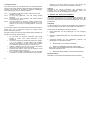
4 1/2-stellige LCD-Anzeige
Anschluss für USB-Schnittstellenkabel
Taste für Messwerthaltefunktion (Data-Hold)
Ein/Aus-Taste
Taste für Relativwertmessfunktion (REL)
Taste zur manuellen Bereichswahl (R-H)
Taste für Minimal- und Maximalwerthaltefunktion (MIN/MAX)
Taste zum Ein- und Ausschalten der
Hintergrundbeleuchtung
SET-Taste zum Umschalten der Unterfunktionen
Funktions – und Bereichswahlschalter
LED-Leuchten zur Anzeige der zu verwendenden
Eingangsbuchsen
20 A-Eingangsbuchse
mA – Eingangsbuchse
COM – Eingangsbuchse
V/Ω – Eingangsbuchse
3.
Connect the test leads to the DC voltage source you want to
measure.
Notes:
* If polarity is negative, - appears on the left of display.
*
For the most accurate measurement, select the lowest possible
voltage range without getting an overload reading.
*
Input Impedance: 10 MΩ on all ranges.
2.2. Measuring AC Voltage
WARNING! Do not try to measure a voltage greater than 750 Volts AC
since it may damage your meter and expose yourself to a severe
shock hazard.
Follow these steps to measure AC voltage:
2.1. Beschreibung
1.
20 A-Eingang (12):
Zum Anschluss der roten Prüfleitung bei AC/DC-Strommessungen im
A-Bereich bis max. 20 A (Funktions-/Bereichswahlschalter (10) in
Stellung “20 A”)
Set the rotary selector to the desired position. Select the range as
required for the voltage level to be measured. If you do not know
the voltage level, start with the rotary selector set to the highest
voltage position and reduce the setting as needed to get a reading.
2. Press SET-button (9) to select AC.
mA-Eingang (13)
Zum Anschluss der roten Prüfleitung bei AC/DC-Strommessungen im
mA-Bereich (Funktions-/Bereichswahlschalter (10) in Stellung “µA” ).
3. Plug the black test lead into the meter’s COM terminal and the red
test lead into the V/Ω terminal.
COM-Eingang (14):
Zum Anschluss der schwarzen Prüfleitung (alle Messfunktionen)
4. Connect the test leads to the AC voltage source you want to
measure.
V/Ω-Eingang (15):
Zum Anschluss der roten Prüfleitung bei Spannungs-, Widerstandsund Frequenzmessungen sowie für die Messfunktionen Diodentest
und Durchgangsprüfungen.
Notes:
•
•
11
Input impedance:approximately 10 MΩ in parallel with less
than 100 pF.
Frequency response: 40 Hz to max. 20 kHz.
36