1
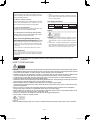
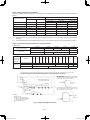
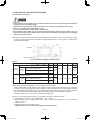
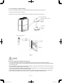
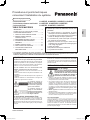
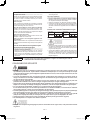
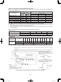
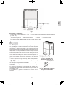
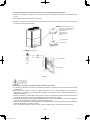
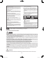
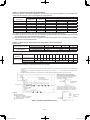
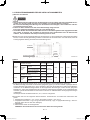
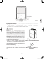
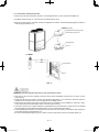
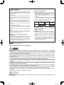
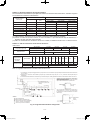
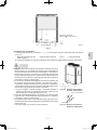
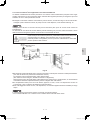
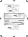
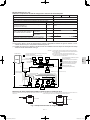
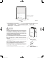
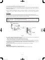
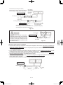
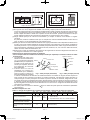
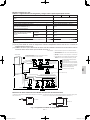
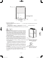
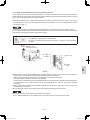
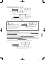
(Top view)
(Front view)
Over 1 cm
Over 95 cm
Refrigerant tubing side
Over 55 cm
Over 35 cm
Over
1 cm
Over
15 cm
Over
10 cm
Over
10 cm
Over m
95 cm
Over
10 cm
Over 60 cm
Over
2m
Over 15 cm
Maintenance Space
Required distance from flammable materials
Fig. 1
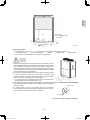
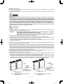
Fig. 2
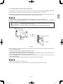
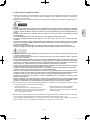
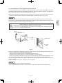
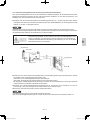
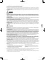
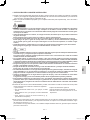
(3) In snowy regions, be sure to install a snow-protection hood and enclosure.
Even in regions that do not have heavy snowfall, install a snow-protection roof (such as a snow hood) if the
unit is installed in a location where snow may build up and fall from the building’s roof or other surface onto
the unit. (Install the hood so that the coolant supply opening at the top of the unit can be used.)
(4) Take care that operating noise and exhaust do not disturb neighboring buildings or homes.
In particular, install so that noise-related local environmental standards, if any, are satisfied at the border
with a neighboring dwelling.
(5) Because this gas heat pump A/C may affect other electrical devices with noise, give due consideration when
installing AC units (both indoors and outdoors) at enough distance (at least 3 m) from the main unit of TVs,
radios, stereos, intercoms, PCs, word processors, telephones, etc., as well as their antenna cables, signal
wires, power cords, etc.
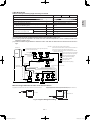
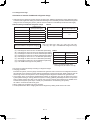
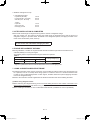
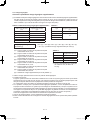
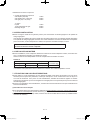
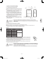
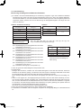
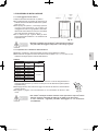
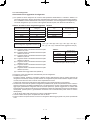
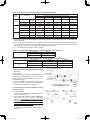
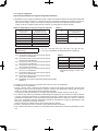
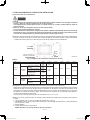
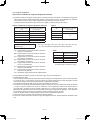
(6) Select an installation location so that the length of refrigerant tubing is within the ranges shown in the table
below.
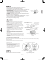
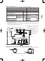
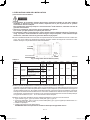
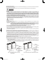
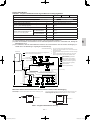
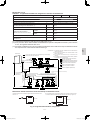
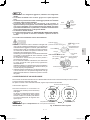
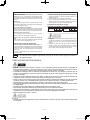
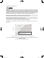
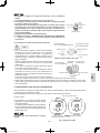
Warnings (Same for All Models)
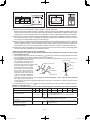
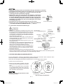
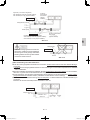
*Always use R410A branch tubes (sold separately) when running branching tubes.
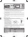
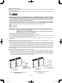
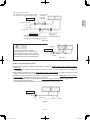
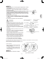
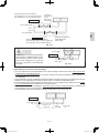
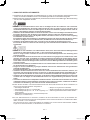
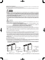
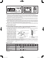
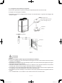
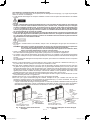
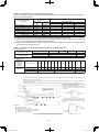
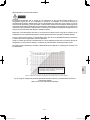
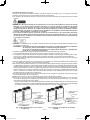
1. Warnings about using branch tubes (
) and header tubes sold separately will come packaged with
the parts sold separately, so be sure to
Closed weld
refer to those materials.
Any angle
2. When using a T-tee branch tube
Indoor
Level line
(provided by installer) (only with L3 at
Outdoor
Indoor
2 m or less), the main tubing must be
Indoor
either level or vertical. The openings of
Raised angle
each branch tube must be at a raised
(15 to 30 degrees)
L3<2m
Indoor
angle from the ground when the main
tubing is level. The openings can be set
Indoor
Closed weld
Outdoor
at any angle when the main tubing is
vertical, but be sure to curve a portion
Fig. 3 Main tube (horizontal)
Fig. 4 Main tube (vertical)
of the connected tubing upward. Always
close weld the end point of the T-tee tubing. In addition, pay special attention to the insertion dimensions
for each connected tube so that refrigerant flow is not blocked at the T-tee branches. Be sure to use only
standard T-tees.
3. Do not use off the shelf Y-joints (
) for liquid tubes (branch tubes (made on site)).
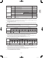
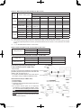
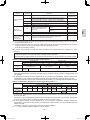
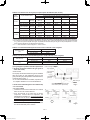
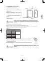
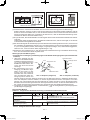
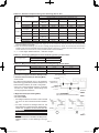
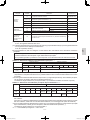
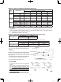
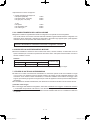
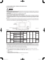
2-Way Multi Models
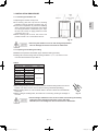
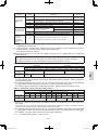
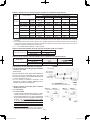
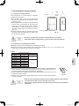
Table 1-1 Ranges for Refrigerant Tubing Length and Installation Height Difference
Equivalent Horsepower
Ratio of capacity for indoor unit to
outdoor units
450
560
710
850
450×2
450+560
560×2
450+710
560+710
710×2
16
20
25
30
32
36
40
41
45
50
50 – 130%
Minimum capacity of indoor units that
can be connected
Maximum number of indoor units that
can be connected (per system)
50 –
170%
Min: Across the system, a minimum outdoor unit capacity of 50%
Max: Total capacity of 130% with 2 outdoor units
Type 22 or greater (equivalent to 0.8 horsepower)
24
34
48 (A maximum of 24 indoor units can be connected per
1 outdoor unit)
* The number of indoor units that can be connected when a W-multi outdoor unit is installed by itself
is 24 units or fewer.
EN - 4
00-Installation_All.indb 4
2012/03/05 14:31:55