1
スケールユニット / Scale Unit / Maßstabseinheit
BL55-RU
お買い上げいただき、ありがとうございます。
ご使用の前に、この説明書を必ずお読みください。
ご使用に際しては、この説明書どおりお使いください。
お読みになった後は、後日お役に立つこともございますので、必ず保管してください。
Read all the instructions in the installation manual carefully before use and strictly follow
them.
Keep the manual for future references.
Lesen Sie die ganze Anleitung vor dem Betrieb aufmerksam durch und folgen Sie beim
Betrieb des Geräts den Anweisungen. Bewahren Sie diese Anbringungsanleitung zum
späferen Nachlesen griffbereit auf.
取付説明書 / Installation Manual / Anbringungsanleitung
BL55-RU
安全のために
警告
当社の製品は安全に充分配慮して設計されています。
しかし、操作や設置時にまちがった取扱いをすると、
火災や感電などにより死亡や大ケガなど人身事故につ
ながることがあり、危険です。また、機械の性能を落
としてしまうこともあります。
これらの事故を未然に防ぐために、安全のための注意事
項は必ず守ってください。操作や設置、保守、点検、修
理などを行う前に、この「安全のために」を必ずお読み
ください。
警告表示の意味
このマニュアルでは、次のような表示をしています。
表示内容をよく理解してから本文をお読みください。
警告
この表示の注意事項を守らないと、火災や感電などに
より死亡や大ケガなど人身事故につながることがあり
ます。
注意
この表示の注意事項を守らないと、感電やその他事故
によりケガをしたり周辺の物品に損害を与えることが
あります。
感電注意
· 濡れた手による取付作業はおやめくだ
さい。感電の原因となる恐れがありま
す。
· 本体を分解や改造しないでください。
ケガの恐れや、内部回路が破損するこ
とがあります。
· 本装置は、半導体レーザを使用したク
ラス1レーザ製品です。本装置に使用し
ている半導体レーザの波長は可視帯域
から外れた790 nm、最大出力は6 mW
(クラス3B) です。
· ヘッド内部から照射されるレーザ光は
目に見えませんが、人体に有害です。
スケールユニットを分解したり、ス
ケールシール部から中を覗きこんだり
しないでください。また、スケールユ
ニットのシール部から異物を差し込ま
ないでください。
· 本装置は次ページの規格、基準に適合
しています。
注意を促す記号
注意
· 表示された電源電圧以外での電圧で使
用しないでください。火災や感電の原
因となる恐れがあります。
指はさみ注意
レーザ注意
行為を禁止する記号
分解禁止
行為を指示する記号
プラグの取外し
BL55-RU
(J) (1)
日本工業規格 : JIS C6802
レーザ製品の安全基準に適合しています。
クラス1レーザ製品
CDRH規定
米国食品医薬品局CDRH (Center for Devices and
Radiological Health) のレーザ製品に関する規定 (1976年
8月1日施行) に適合しています。
米国内で販売される製品はこの規準に適合する必要が
あります。
注意
· 作業を行なう前には、装置の状況をよ
く確かめて作業の安全を確保してくだ
さい。
· 電源などの駆動源は必ず切って作業を
してください。火災や事故の原因とな
ります。
· 電源などを入れて動かす場合は、周辺
機械や装置などに指を挟まれないよう
に充分注意してください。
CLASS 1 LASER PRODUCT
国際規格
EN60825-1を含む該当する安全基準に適合していま
す。
CLASS 1 LASER PRODUCT
LASERSCHUTZKLASSE 1 PRODUKT
TO EN 60825
(2) (J)
BL55-RU
使用上の注意事項
使用環境によるご注意
· インターフェイスユニットのコネクタプラグには静
電気保護用キャップが付いていますので、周辺機器
接続時まで取り外さないでください。
また、コネクタプラグの静電気保護キャップ取り外
し後に、コネクタピンに触れないように特に注意し
てください。故障の原因となります。
· インターフェイスユニットのコネクタと周辺機器を
完全に接続してから電源スイッチをONにしてくだ
さい。
また、電源をONしたままコネクタを抜き差ししな
いでください。
· ケーブルを強く引いたり、無理に曲げてのご使用は
避けてください。{曲げ半径 (内側) 静止状態 : 30 mm
以上、可動状態 : 100 mm以上}
· 電源投入後10分位経過しますと、検出ヘッド部の温
度が安定状態となります。その後にご使用くださ
い。
· 本品は精密測定器のため、過度の衝撃が加わらない
よう取扱いには充分注意してください。また、輸送
するときは必ず製品購入時と同じ包装形態でお願い
します。接続コネクタ部の静電気保護キャップも必
ず取付けてください。
q、wの環境下でご使用になる場合、必ず下記対策を
行なってください。
行なわない場合は、品質保証できません。
q 水溶性切削液を使用する場合 / 金属微粉末が発生
する加工やセラミック、グラスファイバーなどの
加工物を加工する場合
w ホーミングマシンのような、長時間特定区間を高
速摺動する機械に装着する場合
· 水溶性切削液や切屑が直接スケールにかからない場
所に取付けてください。
· 内部に水溶性切削液のミストや粉塵が侵入しないよ
うに、スケールカバーを取付けてください。
· エアフィルタやミストセパレータなどを通したク
リーンエアーを注入してください。
保存上のご注意
· 高温・高湿になるところには保管しないでくださ
い。
性能劣化の原因となりますので、できるだけ乾燥し
た場所に保管してください。
一般的注意事項
設置上のご注意
本機を設置するときは、他の機器からのノイズ、電磁
波障害などを防止するため、以下の点に注意してくだ
さい。
· ヘッドケーブルおよび接続ケーブルは、動力線と同
じダクトには通さないでください。
· 高電圧源、大電流源および大電力リレーからは必ず
0.5 m以上離して設置してください。
取付場所についてのご注意
· スケールは機械の加工物、測定物のできるだけ近く
に取付けてください。
· 本製品は、周囲温度0∼40 °Cの範囲内でご使用くだ
さい。
直射日光や熱風の当たる場所や、モータなどの近く
で熱源のある場所への取付けは避けてください。精
度悪化の原因となります。
· 取付けられたスケールの上にものを置いたり、作業
者がひじや足を掛けるなど、無理な力をかけること
は絶対に避けてください。
BL55-RU
以下は当社製品を正しくお使いいただくための一般的
注意事項です。個々の詳細な取扱上の注意は、本取扱
説明書に記述された諸事項および注意をうながしてい
る説明事項に従い、正しくお使いください。
· 始業または操作時には、当社製品の機能および性能
が正常に作動していることを確認してからご使用く
ださい。
· 当社製品が万一故障した場合、各種の損害を防止す
るための充分な保全対策を施してご使用ください。
· 仕様に示された規格以外での使用または改造を施さ
れた製品については、機能および性能の保証はでき
ませんのでご留意ください。
· 当社製品を他の機器と組合せてご使用になる場合
は、使用条件、環境などにより、その機能および性
能が満足されない場合がありますので、充分ご検討
の上ご使用ください。
(J) (3)
[For U.S.A. and Canada]
[ For EU and EFTA countries ]
THIS CLASS A DIGITAL DEVICE COMPLIES WITH
PART15 OF THE FCC RULES AND THE CANADIAN
ICES-003. OPERATION IS SUBJECT TO THE
FOLLOWING TWO CONDITIONS.
(1) THIS DEVICE MAY NOT CAUSE HARMFUL
INTERFERENCE, AND
(2) T H I S D E V I C E M U S T A C C E P T A N Y
INTERFERENCE RECEIVED, INCLUDING
INTERFERENCE THAT
MAY CAUSE UNDERSIGNED OPERATION.
CE Notice
Marking by the symbol CE indicates compliance with
the EMC directive of the European Community. This
marking shows conformity to the following technical
standards.
EN 55011 Group 1 Class A / 98 :
"Limits and methods of measurement of radio
disturbance characteristics of industrial, scientific and
medical (ISM) radio-frequency equipment"
EN 61000-6-2 / 99 :
CET APPAREIL NUMERIQUE DE LA CLASSE A
EST CONFORME A LA NORME NMB-003 DU
CANADA.
"Electromagnetic compatibility (EMC) - Part 6-2 :
Generic standards - Immunity for industrial
environments"
For DC power-driven products to meet EN 61000-6-2 / 99,
the following operational conditions must be satisfied.
1. Input and output signal cable length : 30 m or less
2. Cable length for input power source : 10 m or less
3. Scale cable length
: 30 m or less
Note
When using the same cable for output signal and input
power source, the cable must not be longer than 10 m.
For AC power-driven products to meet EN 61000-6-2 / 99,
the following operational conditions must be satisfied.
1. Input and output signal cable length : 30 m or less
2. Scale cable length
: 30 m or less
警告
本装置を機械指令 (EN 60204-1) の適合を受ける機器
にご使用の場合は、その規格に適合するように方策
を講じてから、ご使用ください。
Warning
When using this device with equipment governed by
Machine Directives EN 60204-1, measures should be
taken to ensure conformance with those directives.
Warnung
Wenn dieses Gerät mit Ausrüstungsteilen verwendet
wird, die von den Maschinenrichtlinien EN 60204-1
geregelt werden, müssen Maßnahmen ergriffen
werden, um eine Übereinstimmung mit diesen
Normen zu gewährleisten.
(4) (J)
BL55-RU
このたびは、当社の製品をお買い上げいただき、まことにありがとうございます。
ご使用方法は別売のBL55-RU取扱説明書をお読みください。
1. 機種構成
型名
有効長
BL55-007RU ······
70 mm
0
BL55-012RU ······
120 mm
0
BL55-017RU ······
170 mm
0
BL55-022RU ······
220 mm
0
BL55-027RU ······
270 mm
0
BL55-032RU ······
320 mm
0
BL55-037RU ······
370 mm
0
BL55-042RU ······
420 mm
0
BL55-047RU ······
470 mm
0
BL55-052RU ······
520 mm
1
BL55-057RU ······
570 mm
1
BL55-062RU ······
620 mm
1
BL55-072RU ······
720 mm
1
BL55-077RU ······
770 mm
1
BL55-082RU ······
820 mm
1
BL55-087RU ······
870 mm
1
BL55-092RU ······
920 mm
1
BL55-102RU ······
1020 mm
2
B L 5 5 − *** R U □ △
中間フットの数
###
原点位置の指示 [mm] (注1)
L : 左有効長端から
C : センター
R : 右有効長端から
RV : リバース原点
スケール精度 5 : ±2.5 µm
6 : ±4.5 µm
出力形態 F : A / B相出力 (0.1 / 0.05 µm)
G : A / B相出力 (0.02 / 0.01 µm)
H : アナログ出力
シールド型原点付スケール
有効長 (cm)
型式
注1 : 原点位置は有効長端からの距離となります。有効長端から4 mm以下の範囲は指定するこ
とができません。
[例]
BL55-052RUF6 L-10
: 520 mm・シールド型原点付・A / B相出力 (0.1 / 0.05 µm)・±4.5 µm・
左有効長端から10 mm
BL55-102RUH6 C
: 1020 mm・シールド型原点付・アナログ出力・±4.5 µm・センター
BL55-007RUG5 R-60RV : 70 mm・シールド型原点付・A / B相出力 (0.02 / 0.01 µm)・±2.5 µm・
右有効長端から60 mmのリバース原点
BL55-RU
(J) 1
2. 取付に必要なもの
付属品
数量
六角穴付ボルト
M8 × 25
スケール取付け用
2
六角穴付ボルト
M4 × 25
スライダ取付け用
2
中間フット取付け用
(中間フットは有効長470 mm以下...0個、
520∼920 mm...1個、1020 mm...2個付いています。)
2
ヘッドケーブル固定用
2
六角穴付ボルト
M2.6 × 16
六角ナット
呼び4
六角穴付ボルト
M4 × 10
配線止め用
6
スプリングワッシャ
呼び4
スライダ取付け用
2
スプリングワッシャ
呼び4
中間フット取付け用
2
ヘッドケーブル固定用
2
t = 0.05
スライダ取付け用
2
t = 0.1
スライダ取付け用
3
配線止め
スペーサ
六角穴付ハーフユニオン
2
空気注入用
3
ワッシャ
みがき丸呼び4
2
六角穴付ボルト
M4 × 12
2
インターフェイスユニット用
付属品以外に下記の部品と工具をご用意ください。
スケール取付用ブラケット (A / B面相当部品)
1∼2
スライダ取付用ブラケット (C面相当部品)
1
0.01 mmピックテスタ (またはダイアルゲージ)
1∼2
LレンチM2.6用 (対辺2 mm)
1
LレンチM4用 (対辺3 mm)
1
LレンチM8用 (対辺7 mm)
1
タップM4
1
タップM8
1
ドリルφ 3.2
1
ドリルφ 6.8
1
電気ドリル
1
ライナ / スペーサ (0.05∼0.2 t)
少々
ドライバ2号 (+)
1
2 (J)
BL55-RU
70.5
9
61.5 ±0.1
23.8
4.5
有効長 : L
70
120
170
220
270
320
370
420
470
520
570
620
720
770
820
870
920
1020
型名
BL55-007RU∗∗
BL55-012RU∗∗
BL55-017RU∗∗
BL55-022RU∗∗
BL55-027RU∗∗
BL55-032RU∗∗
BL55-037RU∗∗
BL55-042RU∗∗
BL55-047RU∗∗
BL55-052RU∗∗
BL55-057RU∗∗
BL55-062RU∗∗
BL55-072RU∗∗
BL55-077RU∗∗
BL55-082RU∗∗
BL55-087RU∗∗
BL55-092RU∗∗
BL55-102RU∗∗
六角穴付
ハーフユニオン
0
0
0
0
0
0
0
0
0
329
354
379
429
454
479
504
529
386
F1
0
0
0
0
0
0
0
0
0
0
0
0
0
0
0
0
0
385
F2
28.5
9.5
M1
8
30
(9.5)
有効長 (L)
30
20
12
56 ±0.2
88
70 ±0.1
110
4
4
(12)
2-ø8.5
(M8用取付穴)
単位 : mm
ケーブル長1000
(最長3000)
2-ø4.2
(M4用取付穴)
0.75
ø6
1
1 18 1±0.1
20
スプリングワッシャ
(呼び4)
M4 × 25
M8 × 25
M4 × 25
スプリングワッシャ
(呼び4)
23
(35)
2-4.6 × 8.6長穴
(M4用取付穴)
9.5
ø4.2 (M4用取付穴)
(注1) 有効長 : 120 mm以下の場合 平行度0.05 mm以下。
(注2) 有効長 : 170 mm以上の場合 平行度0.1 mm以下。
(注3) Mはマシンガイド (機械の走り) を示す。
F1 ±0.1
42
32.3 ±0.2
9.8
有効長 (L) + 137
有効長 (L) + 118 ±0.2
F2 ±0.1
32 ±0.1
5
9
41.7
BL55-RU
18.8
0.05 M
0.03
0.03 M
0.02
0.1 M
0.05
0.1 M
0.1
(注2)
0.05 M
0.05
(注1)
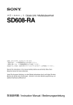
3. 取付面の加工寸法
· 図に指示するねじ (六角穴付ボルト) は、標準付属品とします。
· 有効長が520 mm 以上のスケールは、中間フットが必要です。
· 有効長を超えてスケールを動かすと破損します。機械可動長が有効長内に入るよう、充分注意してください。
(J) 3
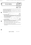
4. スケールユニットとスライダの取付け
平行度0.05 mm/M
(有効長120 mm以下)
25
10
平行度0.1 mm/M
(有効長170 mm以上)
20
10
10
M8 × 25
締付トルク22 N · m
25
M4 × 25
締付トルク2.7 N · m
M4 × 25
締付トルク2.7 N · m
M8 × 25
締付トルク22 N · m
※ Mはマシンガイド (機械の走り) を示す。
単位 : mm
· スケールユニットの両端および中間フットの付近で、図に示す平行度を出してください。
· スケール取付ねじは一度に締めず、仮締めし、平行度を出したあとに規定トルクで締めてくだ
さい。
· 有効長520 mm以上のスケールの場合、中間フットも固定してください。
4 (J)
BL55-RU
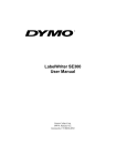
5. スライダの取付け確認
スケールユニットとスライダの隙間に、スライダ固定板のリブ部分がスムーズに入ることを確認
します。(スライダ固定板のリブ部分の厚み : 1 mm)
スライダ固定板
リブ
スライダ固定板が入らない場合もしくは大きくがたつく場合は、基準通りの取付けがされていま
せんので、スケールとスライダの取付けを再度、最初から行なってください。
6. 空気注入について
空気注入口は、スケールユニット両端およびスライダの計3箇所にあります。
詳細は取扱説明書 (別売) をご確認ください。
ユニオン
適用チューブ外形
BL55-RU
(J) 5
7. インターフェイスユニットの設定
ON
43
2
出荷時状態
(出力形態
F, Hの場合)
1
POS.ランプ
1
2
3
4
5
6
7
8
9
10
1
2
3
4
5
6
7
8
9
10
ON
出荷時状態
(出力形態
Gの場合)
MODEスイッチ (各種設定用)
MODEスイッチ1
MODEスイッチ2
MODEスイッチ3
MODEスイッチ4
MODEスイッチ5
MODEスイッチ6
MODEスイッチ7
MODEスイッチ8
MODEスイッチ9
MODEスイッチ10
MODEスイッチ
A / B相出力タイプ
1, 2
POS. ランプ点灯
(原点POS 1 sw)
(原点POS 2 sw)
(Dir・sw)
(常時OFF)
(原点調整モードsw)
(分解能設定sw)
(常時OFF)
(アラームモードsw)
(常時OFF)
(原点モードsw)
アナログ出力タイプ
MODEスイッチ1
MODEスイッチ2
MODEスイッチ1 ...... 常時ON
4
OFF
OFF
MODEスイッチ2 ...... 常時OFF
3
ON
OFF
2
OFF
ON
1
ON
ON
3
ON ............. B相が進む
OFF ............ A相が進む
常時OFF
4
常時OFF
常時OFF
5
通常ON
原点調整時のみOFF
常時ON
6
出力形態F : ON ............ 0.1 µm
OFF .......... 0.05 µm
7
常時OFF
常時OFF
8
ON ............. 保持モード
OFF ............ 自動解除モード
常時OFF
9
常時OFF
常時OFF
10
ON ............. 1/4原点モード
OFF ............ 原点モード
常時OFF
出力形態G : ON ............ 0.02 µm
OFF .......... 0.01 µm
常時ON
設定変更についての詳細は、取扱説明書 (別売) をご確認ください。
6 (J)
BL55-RU
8. 入出力コネクタ
8-1. コネクタ
インターフェイスユニット側
ケーブル側
ピン記号
: R04-R12M (多治見無線電機 (株) 製)
: R04-P12F (多治見無線電機 (株) 製) ............. 防水タイプ
: R03-PB12F (多治見無線電機 (株) 製) .......... 非防水タイプ
入出力仕様
A / B相出力
アナログ出力
A
A
+COS
B
∗A
−COS
C
B
+SIN
D
∗B
−SIN
A B
E
Z
+REF
C D E F
F
∗Z
−REF
G H
G
+5 V (電源)
H
0 V (電源)
J
0 V (信号)
K
0 V (信号)
L
+5 V S
M
0VS
J
K
L M
注意
· 0 Vは回路GNDであり、フレームGNDとは接続されていません。
· 電源電圧は、インターフェイスユニット入力部でDC 5 V ±5 %を満足するようにしてください。
· +5 V S、0 V Sはインターフェイスユニット入力部にかかる電圧のチェック (リモートセンシ
ング機能) 用です。ケーブルによる電源電圧降下の確認や制御に使用できます。また、電源変
動を制御できない電源を使用する場合は、電源入力端子として使用することでケーブル長によ
る電源電圧降下を半減することができますので、+5 V、0 V (電源) にそれぞれ接続してくだ
さい。
· ケーブルの太さは、AWG28∼24が適当です。
· 誤配線防止のため、0 V端子はすべて接続してください。
· ケーブルは、シールドされたケーブルをご使用ください。
· 出力信号は、ツイストペア線をご使用ください。
A・∗A、B・∗B、Z・∗Z、+SIN・−SIN、+COS・−COS、+REF・−REFをそれぞれペアでご使用
ください。
BL55-RU
(J) 7
8 (J)
BL55-RU
Safety Precautions
Warning
Magnescale Co., Ltd. products are designed in full
consideration of safety. However, improper handling
during operation or installation is dangerous and may
lead to fire, electric shock or other accidents resulting
in serious injury or death. In addition, these actions
may also worsen machine performance.
Therefore, be sure to observe the following safety precautions in order to prevent these types of accidents,
and to read these “Safety Precautions” before operating, installing, maintaining, inspecting, repairing or otherwise working on this unit.
• Do not use this unit with voltages other
than the specified supply voltages as this
may result in fire or electric shock.
Warning indication meanings
• This device is a class 1 laser product
using a semiconductor laser with wavelength of 790 nm that is outside the visible range. The maximum output of the
laser is 6 mW (class 3B).
The following indications are used throughout this
manual, and their contents should be understood before reading the text.
Warning
Failure to observe these precautions may lead to fire,
electric shock or other accidents resulting in serious
injury or death.
Caution
Failure to observe these precautions may lead to electric shock or other accidents resulting in injury or damage to surrounding objects.
• Do not perform installation work with wet
hands as this may result in electric
shock.
• Do not disassemble or modify the unit
as this may result in injury or damage
the internal circuits.
• Although the laser beams emitted from
the head interior are invisible to the eye,
they are hazardous to the human body.
Therefore, never disassemble the scale
unit, or try to look into it from the sealed
section of the scale unit. Also, never insert foreign objects into the sealed section of the scale unit.
CLASS 1 LASER PRODUCT
Symbols requiring attention
LASERSCHUTZKLASSE 1 PRODUKT
TO EN 60825
CAUTION
ELECTRICAL
SHOCK
FINGER JAM
LASER BEAM
Symbols prohibiting actions
DO NOT
DISASSEMBLE
Symbols specifying actions
UNPLUGGING
BL55-RU
(E) (1)
Caution
• Be sure to check the machine and device conditions to ensure work safety
before working on the machine.
CAUTION
Use of controls or adjustments or perfomance of procedures other than those specified herein may result in
hazardous radiation exposure.
• Be sure to cut off the power supply and
other sources of drive power before
working on the machine. Failure to do
so may result in fire or accidents.
• When turning on the power supply or
other sources of drive power to operate
the machine, take care not to catch your
fingers in peripheral machines and devices.
w
q
e
r
q Laser Danger label
See Manual
w DHHS label
CERTIFICATION
PRODUCT COMPLIES WITH DHHS RULES 21
CFR SUBCHAPTER J APPLICABLE AT DATE
OF MANUFACTURE.
Magnescale Co., Ltd.
Shinagawa Intercity Tower A-18F, 2-15-1,
Konan, Minato-ku, Tokyo 108-6018, Japan
MANUFACTURED AT ISEHARA PLANT
Magnescale Co., Ltd.
2-933-725-
∗∗
e Specification label
BL55
*****
DC
S e r i a l
+5V
No.* * * * * *
Magnescale Co., Ltd.
MADE
IN
JAPAN
r FCC label
THIS DEVICE COMPLIES WITH PART 15 OF
THE FCC RULES. OPERATION IS SUBJECT TO
THE FOLLOWING TWO CONDITIONS :
(1) THIS DEVICE MAY NOT CAUSE HARMFUL
INTERFERENCE, AND
(2) THIS DEVICE MUST ACCEPT
ANY INTERFERENCE RECEIVED,
INCLUDING INTERFERENCE THAT MAY CAUSE
UNDESIRED OPERATION.
∗-∗∗∗-∗∗∗-∗∗
(2) (E)
BL55-RU
Operating Precautions
Notes on operating environment
• An antistatic cap is attached to the connector plug of
the interface unit. Do not remove this cap until you
are ready to connect the peripherals.
After removing the static electricity proof cap, take
care not to touch the connector pins as this might
cause malfunctions.
• Be sure to make all connections of the interface unit
connector and the peripherals before switching the
power on.
Never insert or pull out the connector when the power
switch is on.
• Do not pull at the cable forcibly or bend it excessively.
(Bending radius (inside) Static: 30 mm or more,
Moving: 100 mm or more)
• Use the BL55-RU approximately 10 minutes after
power is supplied to the unit, when the temperature
of the detector head reaches a stable state.
• The BL55-RU is a precision measuring instrument.
Handle it with extreme care so that no excessive
shock is applied to it. For transport, be sure to pack
it in the same way as it was packed at the time of
purchase. Be sure to always attach the antistatic
cap to the connector.
If using the scale unit in environments q or w below,
be sure to always take the following preventative measures. If these measures are not taken, scale quality
cannot be guaranteed.
q When using a water-based cutting fluid, performing machining where fine metal dust is produced, or machining ceramic, fiberglass, and
similar types of workpieces
w When installing on a device performing highspeed sliding over a specific area for extended
periods of time, such as a homing machine
• Attach in a location where the water-based cutting
fluid and cuttings do not fall directly on the scale.
• Mount the scale cover so that the mist and particles
from the water-based cutting fluid do not get inside
the scale.
• Inject clean air that passes through an air filter, mist
separator, or other devices.
Notes on installation
Take careful note of the following points when installing
the scale unit to prevent noise and electromagnetic interference from other equipment.
• Do not pass the head cable and connection cable
through the same duct as the power line.
• Install in a location that is at least 0.5 meters separated from sources of high voltage and large currents
and large power relays.
Notes on attachment location
• Attach the scale in a location as near as possible to
the workpiece and measurement object of the machine.
• Use this product in an environment with an ambient
temperature of 0 to 40 °C.
Do not attach it to a location that is exposed to direct
sunlight or warm air or near sources of heat such as
motors. This could adversely affect the accuracy.
• Never place objects on top of the attached scale, rest
your elbows or feet on the scale when using it, or
apply an excessive amount of pressure to the scale.
BL55-RU
Notes on storage
• Do not store in locations with high temperatures or
high humidity.
This could have an adverse effect on scale performance. Store in a location that is as dry as possible.
General Precautions
When using Magnescale Co., Ltd. products, observe
the following general precautions along with those given
specifically in this manual to ensure proper use of the
products.
• Before and during operations, be sure to check that
our products function properly.
• Provide adequate safety measures to prevent damages in case our products should develop malfunctions.
• Use outside indicated specifications or purposes and
modification of our products will void any warranty of
the functions and performance as specified of our
products.
• When using our products in combination with other
equipment, the functions and performance as noted
in this manual may not be attained, depending upon
operating environmental conditions. Make full study
of the compatibility in advance.
(E) (3)
[For U.S.A. and Canada]
[ For EU and EFTA countries ]
THIS CLASS A DIGITAL DEVICE COMPLIES WITH
PART15 OF THE FCC RULES AND THE CANADIAN
ICES-003. OPERATION IS SUBJECT TO THE
FOLLOWING TWO CONDITIONS.
(1) THIS DEVICE MAY NOT CAUSE HARMFUL
INTERFERENCE, AND
(2) T H I S D E V I C E M U S T A C C E P T A N Y
INTERFERENCE RECEIVED, INCLUDING
INTERFERENCE THAT
MAY CAUSE UNDERSIGNED OPERATION.
CE Notice
Marking by the symbol CE indicates compliance with
the EMC directive of the European Community. This
marking shows conformity to the following technical
standards.
EN 55011 Group 1 Class A / 98 :
"Limits and methods of measurement of radio
disturbance characteristics of industrial, scientific and
medical (ISM) radio-frequency equipment"
EN 61000-6-2 / 99 :
CET APPAREIL NUMERIQUE DE LA CLASSE A
EST CONFORME A LA NORME NMB-003 DU
CANADA.
"Electromagnetic compatibility (EMC) - Part 6-2 :
Generic standards - Immunity for industrial
environments"
For DC power-driven products to meet EN 61000-6-2 / 99,
the following operational conditions must be satisfied.
1. Input and output signal cable length : 30 m or less
2. Cable length for input power source : 10 m or less
3. Scale cable length
: 30 m or less
Note
When using the same cable for output signal and input
power source, the cable must not be longer than 10 m.
For AC power-driven products to meet EN 61000-6-2 / 99,
the following operational conditions must be satisfied.
1. Input and output signal cable length : 30 m or less
2. Scale cable length
: 30 m or less
警告
本装置を機械指令 (EN 60204-1) の適合を受ける機器
にご使用の場合は、その規格に適合するように方策
を講じてから、ご使用ください。
Warning
When using this device with equipment governed by
Machine Directives EN 60204-1, measures should be
taken to ensure conformance with those directives.
Warnung
Wenn dieses Gerät mit Ausrüstungsteilen verwendet
wird, die von den Maschinenrichtlinien EN 60204-1
geregelt werden, müssen Maßnahmen ergriffen
werden, um eine Übereinstimmung mit diesen
Normen zu gewährleisten.
(4) (E)
BL55-RU
Thank you for purchasing this Magnescale Co., Ltd. product.
For the operating procedures, refer to the BL55-RU Instruction Manual (sold separately).
1. Series Models
Model name
Measuring length
Number of foot plates
BL55-007RU ·······
70 mm
0
BL55-012RU ·······
120 mm
0
BL55-017RU ·······
170 mm
0
BL55-022RU ·······
220 mm
0
BL55-027RU ·······
270 mm
0
BL55-032RU ·······
320 mm
0
BL55-037RU ·······
370 mm
0
BL55-042RU ·······
420 mm
0
BL55-047RU ·······
470 mm
0
BL55-052RU ·······
520 mm
1
BL55-057RU ·······
570 mm
1
BL55-062RU ·······
620 mm
1
BL55-072RU ·······
720 mm
1
BL55-077RU ·······
770 mm
1
BL55-082RU ·······
820 mm
1
BL55-087RU ·······
870 mm
1
BL55-092RU ·······
920 mm
1
BL55-102RU ·······
1020 mm
2
B L 5 5 − *** R U
###
Reference point position indicator (mm) (Note 1)
L : From the left measuring length edge
C : Center
R : From the right measuring length edge
RV : Reverse reference point
Scale accuracy 5 : ±2.5 µm
6 : ±4.5 µm
Output format
F: A/B signal output (0.1/0.05 µm)
G: A/B signal output (0.02/0.01 µm)
H: Analog output
Shielded-type scale with reference point
Measuring length (cm)
Model
Note 1: The reference point position is the distance from the measuring length edges. Positions less than
4 mm from the measuring length edges cannot be designated.
Examples
BL55-052RUF6 L-10
: 520 mm, shielded-type with reference point, A/B signal output (0.1/0.05 µm),
±4.5 µm, 10 mm from the left measuring length edge
BL55-102RUH6 C
: 1020 mm, shielded-type with reference point, analog output, ±4.5 µm, center
BL55-007RUG5 R-60RV : 70 mm, shielded-type with reference point, A/B signal output (0.02/0.01 µm),
±2.5 µm, reverse reference point that is 60 mm from the right measuring length
edge
BL55-RU
(E) 1
2. Items Required for Installation
Accessories
Quantity
Hex. socket-head cap screw
M8 × 25
For Scale installation
2
Hex. socket-head cap screw
M4 × 25
For Slider installation
2
For foot plate installation
(Measuring length of 470 mm or less:
No foot plate; measuring length of 520 mm
to 920 mm: 1 foot plate; measuring length
of 1020 mm: 2 foot plates)
2
For head cable fastening
2
Hex. socket-head cap screw
M2.6 × 16
Hex. nut
Nominal size 4
Hex. socket-head cap screw
M4 × 10
Spring washer
Nominal size 4 For slider installation
2
Spring washer
Nominal size 4 For foot plate installation
2
For head cable fastening
2
t = 0.05
For slider installation
2
t = 0.1
For slider installation
3
Cable Clamp
Spacer
Hex. socket-head half-unions
2
For cable clamp
For injecting air
Plain washers
Nominal size 4
Hex. socket-head cap screw
M4 × 12
6
3
2
For interface unit
2
In addition to the accessories, obtain the following parts and tools.
Scale installation bracket (for sides A and B)
1-2
Slider installation bracket (for side C)
1
0.01 mm pick tester (or dial gauge)
1-2
Allen wrench M2.6 (Opposite side: 2 mm)
1
Allen wrench M4 (Opposite side: 3 mm)
1
Allen wrench M8 (Opposite side: 7 mm)
1
Tap M4
1
Tap M8
1
Drill φ 3.2
1
Drill φ 6.8
1
Electric drill
1
Liner/spacer (0.05 - 0.2 t)
Small amount
No.2 Phillips screwdriver
1
2 (E)
BL55-RU
Measuring
length: L
70 (2.756")
120 (4.724")
170 (6.693")
220 (8.661")
270 (10.630")
320 (12.598")
370 (14.567")
420 (16.535")
470 (18.504")
520 (20.472")
570 (22.441")
620 (24.409")
720 (28.346")
770 (30.315")
820 (32.283")
870 (34.252")
920 (36.220")
1020 (40.157")
Model name
BL55-007RU∗∗
BL55-012RU∗∗
BL55-017RU∗∗
BL55-022RU∗∗
BL55-027RU∗∗
BL55-032RU∗∗
BL55-037RU∗∗
BL55-042RU∗∗
BL55-047RU∗∗
BL55-052RU∗∗
BL55-057RU∗∗
BL55-062RU∗∗
BL55-072RU∗∗
BL55-077RU∗∗
BL55-082RU∗∗
BL55-087RU∗∗
BL55-092RU∗∗
BL55-102RU∗∗
0 (0.000")
0 (0.000")
0 (0.000")
0 (0.000")
0 (0.000")
0 (0.000")
0 (0.000")
0 (0.000")
0 (0.000")
329 (12.953")
354 (13.937")
379 (14.921")
429 (16.890")
454 (17.874")
479 (18.858")
504 (19.843")
529 (20.827")
386 (15.197")
F1
70.5 (2.776")
61.5 (2.421") ±0.1 (0.004") 9 (0.354")
23.8 (0.937")
32.3(1.272")
±0.2(0.008")
4.5 (0.177")
Hexagonal
socket-head
half-unions
F2
28.5
(1.122")
M1
8
4 (0.157")
20
(0.787") 70 (2.756") ±0.1(0.004")
110 (4.331")
56 (2.205") ±0.2 (0.008")
88 (3.465")
4 (0.157")
(12 (0.472"))
2-ø4.2 (0.165")
(M4 mounting hole)
Unit: mm (inch)
Cable length: 1000 (3.28 ft)
(maximum: 3000 (9.84 ft))
ø6 (0.236")
±0.1 (0.004")
20
(0.787")
1
18
Spring washer
(0.039") (0.709")
(Nominal size 4)
1(0.039")
M4 × 25
M8 × 25
M4 × 25
Spring washer
(Nominal size 4)
2-4.6 × 8.6 elongated hole
(M4 mounting hole)
23
(0.906")
(35 (1.378"))
9.5
(0.374")
Note 1: For a measuring length of 120 mm or less, the parallelism
shall be 0.05 mm max.
Note 2: For a measuring length of 170 mm or more, the parallelism
shall be 0.1 mm max.
Note 3: M refers to the machine guide (machine traveling).
30
(1.181")
(9.5 (0.374"))
12 (0.472")
Measuring length (L)
30
(1.181")
Measuring length (L) + 137 (5.394")
Measuring length (L) + 118 (4.646") ±0.2 (0.008")
F1 ±0.1(0.004")
F2 ±0.1(0.004")
0 (0.000")
0 (0.000")
0 (0.000")
0 (0.000")
0 (0.000")
0 (0.000")
0 (0.000")
0 (0.000")
0 (0.000")
0 (0.000")
0 (0.000")
0 (0.000")
0 (0.000")
0 (0.000")
0 (0.000")
0 (0.000")
0 (0.000")
385 (15.157")
9.8 (0.386")
9.5
(0.374")
42 (1.654")
2-ø8.5 (0.335")
(M8 mounting hole)
5
(0.197")
0.75
(0.030")
ø4.2 (0.165")
(M4 mounting hole)
32(1.260")
±0.1(0.004")
9
(0.354")
18.8
0.1
(0.004")
0.1
(0.004")
0.05
(0.00197") M
0.03
(0.00118")
0.03
(0.00118") M
0.02
(0.00079")
41.7
(1.642")
1 (0.039")
BL55-RU
(0.740")
M
(Note 1)
0.05
(0.00197") M
0.05
(0.00197")
(Note 2)
0.1
(0.00393") M
0.05
(0.00197")
3. Machining Dimensions of Mounting Surface
• The screws (hex. socket-head cap screws) shown in the figure are supplied as standard.
• Scales having an effective length of 520 mm (20.472") or more require a foot plate.
• The scale will be damaged if it moved past the effective length. Be extremely careful that the machine movable length fits
within the measuring length.
(E) 3
4. Installation of Scale Unit and Slider
Parallelism 0.05 mm/M
(Measuring length of
120 mm (4.724") or less)
25 (0.984")
Parallelism 0.1 mm/M
10 (0.394")
(Measuring length of
170 mm (6.693") or more)
20 (0.784")
10 (0.394")
10 (0.394")
M8 × 25
Tightening torque 22 N · m
25 (0.984")
M4 × 25
Tightening torque 2.7 N · m
M4 × 25
Tightening torque 2.7 N · m
M8 × 25
Tightening torque 22 N · m
∗ “M” refers to the machine guide.
Unit: mm (inchi)
• The parallelism shown in the figure should be obtained at both ends of the scale unit and near the foot
plate.
• The scale attachment screws should be temporarily, but not fully tightened, and then tightened to the
specified torque after the parallelism is obtained.
• A foot plate should also be fixed to scales with an effective length of 520 mm (20.472") or more.
4 (E)
BL55-RU
5. Slider Installation Check
Check that the rib section of the slider holding plate fits smoothly into the space between the scale unit and
slider. (Thickness of the rib section of the slider holding plate: 1 mm (0.039"))
Slider holding plate
Rib
The scale and slider were not attached properly if the slider holding plate does not fit or rattles noticeably.
The scale and slider must be attached again from the beginning.
6. Air Injection
The air inlets are located in three locations, at both ends of the scale unit and on the slider.
For details, refer to the Instruction Manual (sold separately).
Union
Outside of suitable tube
BL55-RU
(E) 5
7. Interface Unit Settings
43
21
ON
Default setting
status
(In the case of
output format F, H)
POS. lamp
MODE switches (for various settings)
1
2
3
4
5
6
7
8
9
10
1
2
3
4
5
6
7
8
9
10
ON
Default setting
status
(In the case of
output format G)
MODE switch 1
MODE switch 2
MODE switch 3
MODE switch 4
MODE switch 5
MODE switch 6
MODE switch 7
MODE switch 8
MODE switch 9
MODE switch 10
MODE switches
A/B signal output type
1, 2
POS. lamps light
(Reference point POS1 switch)
(Reference point POS2 switch)
(Direction switch)
(Always off)
(Reference point adjustment mode switch)
(Resolution setting switch)
(Always off)
(Alarm mode switch)
(Always off)
(Reference point mode switch)
Analog output type
MODE switch 1
MODE switch 2
MODE switch 1 ...... Always ON
4
OFF
OFF
MODE switch 2 ...... Always OFF
3
ON
OFF
2
OFF
ON
1
ON
ON
3
ON ............... B signal is leading
OFF .............. A signal is leading
Always OFF
4
Always OFF
Always OFF
5
Normally ON
OFF only during reference point adjustment
Always ON
6
Output format F: ON ..... 0.1 µm
OFF .... 0.05 µm
Always ON
7
Always OFF
Always OFF
8
ON ............... Hold Mode
OFF .............. Automatic Reset Mode
Always OFF
9
Always OFF
Always OFF
10
ON ............... 1/4 Reference Point Mode
OFF .............. Reference Point Mode
Always OFF
Output format G: ON ...... 0.02 µm
OFF .... 0.01 µm
For details about changing the settings, refer to the Instruction Manual (sold separately).
6 (E)
BL55-RU
8. Input/Output Connectors
8-1. Connectors
Interface unit side
: R04-R12M (manufactured by TAJIMI ELECTRONICS CO., LTD.)
Cable side : R04-P12F (manufactured by TAJIMI ELECTRONICS CO., LTD.) ....... Waterproof type
: R03-PB12F (manufactured by TAJIMI ELECTRONICS CO., LTD.) ..... Non-waterproof type
Pin arrangement
Input/output specifications
A/B signal output
Analog output
A
A
+COS
B
∗A
−COS
C
B
+SIN
D
∗B
−SIN
E
Z
+REF
F
∗Z
−REF
G
+5 V (power supply)
H
0 V (power supply)
J
0 V (signal)
K
0 V (signal)
L
+5 V S
M
0VS
A B
C D E F
G H
J
K
L M
• 0 V is the circuit ground, and it is not connected to the frame ground.
• Make sure that the power supply voltage is 5 V DC ±5 % at the input connector to the interface unit.
• +5 V S and 0 V S are for checking the voltage (remote sensing function) applied to the input connector of
the interface unit. These voltages can be used to check and control for drops in the supply voltage due to
the cables. When using a power supply that cannot control power supply fluctuations, a power supply
input terminal can be used to reduce the supply voltage drops occurring due to the cable length. In this
case, connect the cable to the respective +5 V or 0 V power supply.
• The appropriate cable thickness is AWG28 to AWG24.
• Connect all of the 0 V terminals to prevent mis-wiring.
• Use shielded cables for all cabling.
• Use twisted-pair cables for the output signals.
Use cables so that the following signals are paired: A and ∗A, B and ∗B, Z and ∗Z, +SIN and −SIN, +COS
and −COS, +REF and −REF.
BL55-RU
(E) 7
8 (E)
BL55-RU
Sicherheitsmaßnahmen
Bei dem Entwurf von Magnescale Co., Ltd. Produkten
wird größter Wer t auf die Sicherheit gelegt.
Unsachgemäße Handhabung während des Betriebs
oder der Installation ist jedoch gefahrlich und kann zu
Feuer, elektrischen Schlägen oder anderen Unfällen
führen, die schwere Verletzungen oder Tod zur Folge
haben können. Darüber hinaus kann falsche
Anwendung die Leistung der Maschine verschlechtern.
Beachten Sie daher unbedingt die besonders
hervorgehobenen Sicherheitshinweise in dieser
Bedienungsanleitung, um derartige Unfälle zu verhüten,
und lesen Sie die folgenden Sicherheitsmaßnahmen
vor der Inbetriebnahme, Installation, War tung,
Inspektion oder Reparatur dieses Gerätes oder der
Durchführung anderer Arbeiten durch.
Bedeutung der Warnhinweise
Bei der Durchsicht dieses Handbuchs werden Sie auf
die folgenden Hinweise und Symbole stoßen. Machen
Sie sich mit ihrer Bedeutung vertraut, bevor Sie den
Text lesen.
Warnung
Eine Missachtung dieser Hinweise kann zu Feuer,
elektrischen Schlägen oder anderen Unfällen führen,
die schwere Verletzungen oder Tod zur Folge haben
können.
Vorsicht
Eine Missachtung dieser Hinweise kann zu elektrischen
Schlägen oder anderen Unfällen führen, die
Verletzungen oder Sachbeschädigung der umliegenden
Objekte zur Folge haben können.
Zu beachtende Symbole
VORSICHT
ELEKTRISCHER FINGERVERLETZUNG
SCHLAG
LASERSTRAHL
Symbole, die Handlungen verbieten
Warnung
• Betreiben Sie dieses Gerät nur mit der
vorgeschriebenen Versorgungsspannung,
da anderenfalls die Gefahr von Feuer oder
elektrischen Schlägen besteht.
• Führen Sie Installationsarbeiten nicht mit
nassen Händen aus, da hierbei die
Gefahr elektrischer Schläge besonders
groß ist.
• Unterlassen Sie jeden Versuch, das
Gerät zu zerlegen oder umzubauen, da
dies
zu
Verletzungen
oder
Beschädigung der internen Schaltungen
führen kann.
• Dieses Gerät ist ein Laserprodukt der
Klasse 1. Es verwendet einen
Halbleiterlaser mit einer Wellenlänge von
790 nm, dessen Licht außerhalb des
sichtbaren Bereichs liegt. Die maximale
Ausgangsleistung des Lasers beträgt
6 mW (Klasse 3B).
• Obwohl die vom Kopf-Innenbereich
abgegebenen Laserstrahlen für das
Auge unsichtbar sind, stellen sie eine
Gefahr für den menschlichen Körper dar.
Versuchen Sie daher auf keinen Fall, die
Maßstabseinheit zu zerlegen oder von
ihrem versiegelten Teil aus hineinzublicken.
Führen Sie auch niemals Fremdkörper in
den versiegelten Teil der Maßstabseinheit
ein.
CLASS 1 LASER PRODUCT
LASERSCHUTZKLASSE 1 PRODUKT
TO EN 60825
NICHT
ZERLEGEN
Symbole,
die Handlungen vorschreiben
STECKER
ABZIEHEN
BL55-RU
(G) (1)
Vorsicht
• Überprüfen Sie vor Arbeitsbeginn
unbedingt den Zustand von Maschine
und
Vorrichtungen,
um
die
Arbeitssicherheit zu gewährleisten.
ACHTUNG
Die Betätigung von Bedien- und Einstellteilen bzw. die
Ausführung von Verfahren, die nicht in dieser
Bedienungsanleitung beschrieben sind, können zu
gefährlicher Strahlungsbelastung führen.
• Schalten Sie vor Arbeiten an der
Maschine unbedingt die Stromzufuhr
und andere Antriebsstromquellen aus.
Anderenfalls besteht Brand- oder
Unfallgefahr.
• Achten Sie beim Einschalten der
Stromversorgung usw. zum Betrieb der
Maschine darauf, daß Sie sich nicht die
Finger in peripheren Maschinen und
Vorrichtungen klemmen.
w
q
e
r
q Laser-Warnungsetikett
See Manual
w DHHS-Etikett
CERTIFICATION
PRODUCT COMPLIES WITH DHHS RULES 21
CFR SUBCHAPTER J APPLICABLE AT DATE
OF MANUFACTURE.
Magnescale Co., Ltd.
Shinagawa Intercity Tower A-18F, 2-15-1,
Konan, Minato-ku, Tokyo 108-6018, Japan
MANUFACTURED AT ISEHARA PLANT
Magnescale Co., Ltd.
2-933-725-
∗∗
e Spezifikationsetikett
BL55
*****
DC
S e r i a l
+5V
No.* * * * * *
Magnescale Co., Ltd.
MADE
IN
JAPAN
r FCC-Etikett
THIS DEVICE COMPLIES WITH PART 15 OF
THE FCC RULES. OPERATION IS SUBJECT TO
THE FOLLOWING TWO CONDITIONS :
(1) THIS DEVICE MAY NOT CAUSE HARMFUL
INTERFERENCE, AND
(2) THIS DEVICE MUST ACCEPT
ANY INTERFERENCE RECEIVED,
INCLUDING INTERFERENCE THAT MAY CAUSE
UNDESIRED OPERATION.
∗-∗∗∗-∗∗∗-∗∗
(2) (G)
BL55-RU
Vorsichtsmaßregeln zum Betrieb
Hinweise zur Betriebsumgebung
• Der Stecker der Schnittstelleneinheit ist mit einer
Kappe zum Schutz gegen statische Elektrizität
versehen. Entfernen Sie diese Kappe erst unmittelbar
vor dem Anschluß der Peripheriegeräte.
Vermeiden Sie eine Berührung der Steckerkontakte
nach dem Abnehmen der Schutzkappe, weil dies zu
Funktionsstörungen führen könnte.
• Schalten Sie die Stromzufuhr erst ein, nachdem Sie
alle Anschlüsse an Schnittstelleneinheit und
Peripheriegeräte gesichert haben. Der Stecker darf
auf keinen Fall bei eingeschalteter Stromzufuhr
eingeführt oder herausgezogen werden.
• Unterlassen Sie gewaltsames Ziehen oder
übermäßiges Biegen den Kabels. (Biegeradius
(innen) Statisch: mindestens 30 mm, In Bewegung:
mindestens 100 mm)
• Warten Sie vor Benutzung der maßstabseinheit
BL55-RU ungefähr 10 Minuten nach dem Einschalten
der Stromzufuhr, bis sich die Temperatur des
Detektorkopfes stabilisiert hat.
• Die Maßstabseinheit BL55-RU ist ein PräzisionsMeßinstrument. Behandeln Sie sie mit äußerster
Sorgfalt, damit sie keinen starken Erschütterungen
ausgesetzt wird. Benutzen Sie zum Transport die
Originalverpackung der Maßstabseinheit. Bringen
Sie immer die Antistatikkappe am Anschluss an.
Wenn Sie die Maßstabseinheit in den unten
beschriebenen Umgebungen q oder w benutzen,
sollten
Sie
immer
die
folgenden
Vorbeugungsmaßnahmen ergreifen.
Werden diese Maßnahmen nicht ergriffen, kann die
Maßstabsqualität nicht garantiert werden.
q Bei Verwendung einer Schneidflüssigkeit auf
Wasserbasis, Durchführung einer Bearbeitung,
bei der feiner Metallstaub erzeugt wird, oder
Bearbeitung von Keramik, Glasfasern und
ähnlicher Werkstücke
w Bei Montage an einer Vorrichtung, die schnelle
Gleitbewegungen innerhalb eines bestimmten
Bereichs über längere Zeitspannen ausführt, wie
z.B. einer Ziehschleifmaschine
• Bringen Sie die Maßstabseinheit an einer Stelle an,
wo die Schneidflüssigkeit auf Wasserbasis und die
Späne nicht direkt auf den Maßstab fallen können.
• Bringen Sie eine Schutzhaube an, damit der
Sprühnebel und die Teilchen von der
Schneidflüssigkeit auf Wasserbasis nicht in das
Innere des Maßstabs eindringen können.
• Blasen Sie saubere Luft ein, die durch einen Luftfilter,
einen Tropfenabscheider oder ähnliche Vorrichtungen
geleitet wird.
Hinweise zur Lagerung
Hinweise zur Installation
Beachten Sie die folgenden Punkte bei der Montage
der Maßstabseinheit besonders sorgfältig, um
Rauschen und elektromagnetische Störbeeinflussung
von anderen Geräten zu verhüten.
• Führen Sie das Kopfkabel und das Verbindungskabel
nicht durch denselben Kabelkanal wie die
Starkstromleitung der Maschine.
• Montieren Sie die Maßstabseinheit an einer Stelle, die
mindestens 0,5 m Abstand von Hochspannungsquellen,
Starkstromleitungen und großen Leistungsrelais hat.
Hinweise zum Anbringungsort
• Bringen Sie den Maßstab möglichst nahe am
Werkstück und Messobjekt der Maschine an.
• Benutzen Sie dieses Produkt nur an Orten mit einer
Umgebungstemperatur zwischen 0 und 40 °C.
Bringen Sie das Produkt nicht an Orten an, die
direktem Sonnenlicht, Warmluft oder Wärmequellen
(z.B. Motoren) ausgesetzt sind. Dadurch könnte die
Genauigkeit beeinträchtigt werden.
• Stellen Sie niemals Gegenstände auf den montierten
Maßstab, stützen Sie während der Benutzung nicht
Ihre Ellbogen oder Füße auf dem Maßstab ab, und
üben Sie keinen übermäßigen Druck auf den
Maßstab aus.
BL55-RU
• Lagern Sie die Maßstabseinheit nicht an Orten mit
hohen Temperaturen oder hoher Luftfeuchtigkeit. Eine
solche Umgebung könnte sich negativ auf die
Leistung des Maßstabs auswirken. Lagern Sie die
Maßstabseinheit an einem möglichst trockenen Ort.
Allegemeine Vorsichtsmaßregeln
Beachten Sie bei Verwendung unserer Produkte die
folgenden allgemeinen Vorsichtsmaßregeln neben den
in diesem Handbuch speziell vermerkten Hinweisen,
um korrekten Gebrauch der Produkte zu gewährleisten.
• Vergewissern Sie sich vor und während des Betriebs,
daß das Produkt einwandfrei funktioniert.
• Treffen Sie angemessene Sicherheitsmaßnahmen,
um im Falle von Funktionsstörungen Schäden zu
vermeiden.
• Der Einsatz außerhalb der angegebenen
Spezifikationen oder Zwecke und die Modifikation
unserer Produkte haben den Verfall der Garantie auf
die angegebenen Funktionen und Leistungen
unserer Produkte zur Foige.
• Bei Verwendung unserer Produkte in Verbindung mit
anderen Geräten werden je nach den
Betriebsumgebungsbedingungen die in dieser
Anleitung angegebenen Funktionen und Leistungen
möglicherweise nicht erzielt. Daher sollte die
Kompatibilität vorher gründlich überprüft werden.
(G) (3)
[For U.S.A. and Canada]
[ For EU and EFTA countries ]
THIS CLASS A DIGITAL DEVICE COMPLIES WITH
PART15 OF THE FCC RULES AND THE CANADIAN
ICES-003. OPERATION IS SUBJECT TO THE
FOLLOWING TWO CONDITIONS.
(1) THIS DEVICE MAY NOT CAUSE HARMFUL
INTERFERENCE, AND
(2) T H I S D E V I C E M U S T A C C E P T A N Y
INTERFERENCE RECEIVED, INCLUDING
INTERFERENCE THAT
MAY CAUSE UNDERSIGNED OPERATION.
CE Notice
Marking by the symbol CE indicates compliance with
the EMC directive of the European Community. This
marking shows conformity to the following technical
standards.
EN 55011 Group 1 Class A / 98 :
"Limits and methods of measurement of radio
disturbance characteristics of industrial, scientific and
medical (ISM) radio-frequency equipment"
EN 61000-6-2 / 99 :
CET APPAREIL NUMERIQUE DE LA CLASSE A
EST CONFORME A LA NORME NMB-003 DU
CANADA.
"Electromagnetic compatibility (EMC) - Part 6-2 :
Generic standards - Immunity for industrial
environments"
For DC power-driven products to meet EN 61000-6-2 / 99,
the following operational conditions must be satisfied.
1. Input and output signal cable length : 30 m or less
2. Cable length for input power source : 10 m or less
3. Scale cable length
: 30 m or less
Note
When using the same cable for output signal and input
power source, the cable must not be longer than 10 m.
For AC power-driven products to meet EN 61000-6-2 / 99,
the following operational conditions must be satisfied.
1. Input and output signal cable length : 30 m or less
2. Scale cable length
: 30 m or less
警告
本装置を機械指令 (EN 60204-1) の適合を受ける機器
にご使用の場合は、その規格に適合するように方策
を講じてから、ご使用ください。
Warning
When using this device with equipment governed by
Machine Directives EN 60204-1, measures should be
taken to ensure conformance with those directives.
Warnung
Wenn dieses Gerät mit Ausrüstungsteilen verwendet
wird, die von den Maschinenrichtlinien EN 60204-1
geregelt werden, müssen Maßnahmen ergriffen
werden, um eine Übereinstimmung mit diesen
Normen zu gewährleisten.
(4) (G)
BL55-RU
Wir danken Ihnen für den Kauf dieses Produkts von Magnescale Co., Ltd.
Einzelheiten zu den Bedienungsverfahren entnehmen Sie bitte der Bedienungsanleitung des Modells BL55RU (getrennt erhältlich).
1. Modellkonfiguration
Modell
Messlänge
Anzahl der Fußplatten
BL55-007RU ·······
70 mm
0
BL55-012RU ·······
120 mm
0
BL55-017RU ·······
170 mm
0
BL55-022RU ·······
220 mm
0
BL55-027RU ·······
270 mm
0
BL55-032RU ·······
320 mm
0
BL55-037RU ·······
370 mm
0
BL55-042RU ·······
420 mm
0
BL55-047RU ·······
470 mm
0
BL55-052RU ·······
520 mm
1
BL55-057RU ·······
570 mm
1
BL55-062RU ·······
620 mm
1
BL55-072RU ·······
720 mm
1
BL55-077RU ·······
770 mm
1
BL55-082RU ·······
820 mm
1
BL55-087RU ·······
870 mm
1
BL55-092RU ·······
920 mm
1
BL55-102RU ·······
1020 mm
2
B L 5 5 − *** R U
###
Bezugspunktpositionsanzeige (mm) (Hinweise 1)
L : Von der linken Messlängenkante
C : Mitte
R : Von der rechten Messlängenkante
RV : Umkehr-Bezugspunkt
Maßstabsgenauigkeit 5 : ±2,5 µm
6 : ±4,5 µm
Ausgabeformat
F : A/B-Signalausgabe (0,1/0,05 µm)
G : A/B-Signalausgabe (0,02/0,01 µm)
H : Analogausgabe
Abgeschirmter Maßstab mit Bezugspunkt
Messlänge (cm)
Modell
Hinweis 1: Die Bezugspunktposition entspricht dem Abstand von den Messlängenkanten. Positionen von
weniger als 4 mm von den Messlängenkanten können nicht angegeben werden.
Beispiele
BL55-052RUF6 L-10
: 520 mm, abgeschirmte Ausführung mit Bezugspunkt, A/B-Signalausgabe (0,1/
0,05 µm), ±4,5 µm, 10 mm von der linken Messlängenkante
BL55-102RUH6 C
: 1020 mm, abgeschirmte Ausführung mit Bezugspunkt, Analogausgabe, ±4,5
µm, Mitte
BL55-007RUG5 R-60RV : 70 mm, abgeschirmte Ausführung mit Bezugspunkt, A/B-Signalausgabe (0,02/
0,01 µm), ±2,5 µm, Umkehr-Bezugspunkt, der 60 mm Abstand von der rechten
Messlängenkante hat
BL55-RU
(G) 1
2. Für die Montage erforderliche Teile
Zubehör
Menge
Innensechskantschraube
M8 × 25
Zur Befestigung des Maßstabs
2
Innensechskantschraube
M4 × 25
Zur Befestigung des Schiebers
2
Zur Befestigung der Fußplatten
(Messlänge von maximal 470 mm:
keine Fußplatte; Messlänge von 520 mm
bis 920 mm: 1 Fußplatte; Messlänge von
1020 mm: 2 Fußplatten)
2
Zur Befestigung des Kopfkabels
2
Innensechskantschraube
M2,6 × 16
Sechskantmuttern
Nennmaß 4
Innensechskantschraube
M4 × 10
Zur Sicherung der Kabel
6
Federscheiben
Nennmaß 4
Zur Befestigung des Schiebers
2
Federscheiben
Nennmaß 4
Zur Befestigung der Fußplatten
2
Zur Befestigung des Kopfkabels
2
t = 0,05
Zur Befestigung des Schiebers
2
t = 0,1
Zur Befestigung des Schiebers
3
Kabelhalter
Abstandsstück
Innensechskantverbindungen
2
Für Lufteinblasung
3
Unterlegscheiben
Nennmaß 4
2
Innensechskantschraube
M4 × 12
Für Schnittstelleneinheit
2
Neben den Zubehörteilen werden die folgenden Teile und Werkzeuge benötigt.
Halter zur Befestigung des Maßstabs (der Fläche A/B entsprechendes Teil)
1 bis 2
Halter zur Befestigung des Schiebers (der Fläche C entsprechendes Teil)
1
0,01-mm-Spitzenwerttester (oder Messuhr)
1 bis 2
M2,6 L-Schlüssel (2 mm zur Gegenseite)
1
M4 L-Schlüssel (3 mm zur Gegenseite)
1
M8 L-Schlüssel (7 mm zur Gegenseite)
1
M4-Gewindebohrer
1
M8-Gewindebohrer
1
Bohrer φ 3,2
1
Bohrer φ 6,8
1
Elektrische Bohrmaschine
1
Einlagen/Abstandsstück (0,05 bis 0,2 t)
Kleine Menge
Schraubenzieher Nr. 2 (Kreuzschlitz)
1
2 (G)
BL55-RU
70,5
9
61,5 ±0,1
23,8
4,5
F1 ±0,1
Messlänge: L
70
120
170
220
270
320
370
420
470
520
570
620
720
770
820
870
920
1020
Modell
BL55-007RU∗∗
BL55-012RU∗∗
BL55-017RU∗∗
BL55-022RU∗∗
BL55-027RU∗∗
BL55-032RU∗∗
BL55-037RU∗∗
BL55-042RU∗∗
BL55-047RU∗∗
BL55-052RU∗∗
BL55-057RU∗∗
BL55-062RU∗∗
BL55-072RU∗∗
BL55-077RU∗∗
BL55-082RU∗∗
BL55-087RU∗∗
BL55-092RU∗∗
BL55-102RU∗∗
0
0
0
0
0
0
0
0
0
329
354
379
429
454
479
504
529
386
F1
0
0
0
0
0
0
0
0
0
0
0
0
0
0
0
0
0
385
F2
30
(9,5)
Messlänge (L)
30
20
12
56 ±0,2
88
70 ±0,1
110
4
4
9,5
ø6
Kabellänge: 1.000
(maximal: 3.000)
2-ø4,2
(M4 Montageloch)
Federscheiben
(Nennmaß 4)
M4 × 25
M8 × 25
M4 × 25
23
(35)
2-4,6 × 8,6 Langloch
(M4 Montageloch)
(12)
2-ø8,5
(M8 Montageloch)
ø4,2 (M4 Montageloch)
Einheit: mm
Hinweis 1: Bei einer Messlänge von maximal 120 mm darf der Parallelitätsfehler
höchstens 0,05 mm betragen.
Hinweis 2: Bei einer Messlänge von 170 mm oder mehr darf der Parallelitätsfehler
höchstens 0,1 mm betragen.
Hinweis 3: „M” bezieht sich auf die Maschinenführungsbahn.
M1
8
Innensechskantverbindungen
28,5
9,5
42
32,3 ±0,2
9,8
Messlänge (L) + 137
Messlänge (L) + 118 ±0,2
F2 ±0,1
32 ±0,1
5
1
1 18 1±0,1
20
9
41,7
0,75
BL55-RU
18,8
Federscheiben
(Nennmaß 4)
0,05 M
0,03
0,03 M
0,02
0,1
0,1
M
0,1 M
0,05
(Hinweis 2)
0,05 M
0,05
(Hinweis 1)
3. Bearbeitungsmaße der Montagefläche
• Die in der Abbildung gezeigten Schrauben (Innensechskant-Zylinderkopfschrauben) werden als Standardzubehör mitgeliefert.
• Für Maßstäbe mit einer Messlänge von 520 mm oder mehr ist eine Fußplatte erforderlich.
• Der Maßstab wird beschädigt, falls er über die Messlänge hinaus bewegt wird. Achten Sie mit größter Sorgfalt darauf, dass
die Bewegungslänge der Maschine innerhalb der Messlänge liegt.
(G) 3
4. Montage von Maßstabseinheit und Schieber
Parallelität 0,05 mm/M
(Messlänge von maximal 120 mm)
25
10
Parallelität 0,1 mm/M
(Messlänge von
170 mm oder mehr)
20
10
10
M8 × 25
Anzugsmoment 22 N · m
25
M4 × 25
Anzugsmoment 2,7 N · m
M4 × 25
Anzugsmoment 2,7 N · m
M8 × 25
Anzugsmoment 22 N · m
∗ M” bezieht sich auf die Maschinenführungsbahn.
”
Einheit: mm
• Die in der Abbildung gezeigte Parallelität sollte an beiden Enden der Maßstabseinheit und in der Nähe
der Fußplatte erzielt werden.
• Die Befestigungsschrauben des Maßstabs sind zunächst provisorisch, und nach Erzielung der Parallelität
auf das vorgeschriebene Anzugsmoment anzuziehen.
• Maßstäbe mit einer Messlänge von 520 mm oder mehr sind außerdem mit einer Fußplatte zu versehen.
4 (G)
BL55-RU
5. Prüfung der Schiebermontage
Prüfen Sie, ob der Rippenteil der Schieberhalteplatte einwandfrei in den Spalt zwischen Maßstabseinheit
und Schieber passt. (Dicke des Rippenteils der Schieberhalteplatte: 1 mm)
Schieberhalteplatte
Rippe
Maßstab und Schieber sind nicht richtig montiert, wenn die Schieberhalteplatte nicht passt oder merklich
klappert. In diesem Fall müssen Maßstab und Schieber von neuem angebracht werden.
6. Lufteinblasung
Die Lufteinlässe befinden sich an drei Stellen, und zwar an beiden Enden der Maßstabseinheit und am
Schieber.
Einzelheiten entnehmen Sie bitte der Bedienungsanleitung (getrennt erhältlich).
Verbindung
Außenansicht des geeigneten Schlauchs
BL55-RU
(G) 5
7. Einstellungen der Schnittstelleneinheit
43
21
ON
Standardeinstellungszustand
(Im Falle der Ausgabeform F, H)
POS-Lampe
MODE-Schalter
(für verschiedene
Einstellungen)
1
2
3
4
5
6
7
8
9
10
1
2
3
4
5
6
7
8
9
10
ON
Standardeinstellungszustand
(Im Falle der Ausgabeform G)
MODE-Schalter 1
MODE-Schalter 2
MODE-Schalter 3
MODE-Schalter 4
MODE-Schalter 5
MODE-Schalter 6
MODE-Schalter 7
MODE-Schalter 8
MODE-Schalter 9
MODE-Schalter 10
MODE-Schalter
A/B-Signalausgangstyp
1, 2
POS-Lampen Leuchten
(Bezugspunktschalter POS1)
(Bezugspunktschalter POS2)
(Richtungsschalter)
(immer OFF)
(Bezugspunkt-Einstellungsmodusschalter)
(Teilungszahl-Einstellschalter)
(immer OFF)
(Alarmmodusschalter)
(immer OFF)
(Bezugspunktmodusschalter)
Analogausgangstyp
MODE-Schalter 1
MODE-Schalter 2
MODE-Schalter 1 ... Immer ON
4
OFF
OFF
MODE-Schalter 2 ... Immer OFF
3
ON
OFF
2
OFF
ON
1
ON
ON
3
ON ........................ Voreilung des B-Signals
OFF ....................... Voreilung des A-Signals
Immer OFF
4
Immer OFF
Immer OFF
5
Normalerweise ON
OFF nur während der Bezugspunkteinstellung
Immer ON
6
Ausgabeformat F: ON ..... 0,1 µm
OFF ... 0,05 µm
Immer ON
7
Immer OFF
Immer OFF
8
ON ........................ Haltemodus
OFF ....................... Modus für Automatische Zurücksetzung
Immer OFF
9
Immer OFF
Immer OFF
10
ON ........................ 1/4-Bezugspunktmodus
OFF ....................... Bezugspunktmodus
Immer OFF
Ausgabeformat G: ON ..... 0,02 µm
OFF ... 0,01 µm
Einzelheiten über das Ändern der Einstellungen entnehmen Sie bitte der Bedienungsanleitung (getrennt erhältlich).
6 (G)
BL55-RU
8. Ein-/Ausgangsanschluss
8-1. Anschluss
Schnittstelleneinheitsseite
: R04-R12M (hergestellt von der Firma TAJIMI ELECTRONICS CO., LTD.)
Kabelseite : R04-P12F (hergestellt von der Firma TAJIMI ELECTRONICS CO., LTD.) ........... Wasserdichter Typ
: R03-PB12F (hergestellt von der Firma TAJIMI ELECTRONICS CO., LTD.) ........ Nicht-wasserdichter Typ
Stiftanordnung
Ein-/Ausgangsspezifikationen
A/B-Signalenausgang
Analogausgang
A
A
+COS
B
∗A
−COS
C
B
+SIN
D
∗B
−SIN
A B
C D E F
E
Z
+REF
F
∗Z
−REF
G
+5 V (Stromversorgung)
H
0 V (Stromversorgung)
J
0 V (Signal)
K
0 V (Signal)
L
+5 V S
M
0VS
G H
J
K
L M
• 0 V ist die Schaltungserde, und sie ist nicht mit der Rahmenerde verbunden.
• Vergewissern Sie sich, dass die Versorgungsspannung am Eingangsanschluss der Schnittstelleneinheit 5 V Gleichstrom
+ 5 % beträgt.
• +5 V S und 0 V S dienen zur Überprüfung der an den Eingangsanschluss der Schnittstelleneinheit angelegten Spannung
(Fernabtastfunktion). Diese Spannungen können verwendet werden, um einen Abfall der Versorgungsspannung durch die
Kabel zu überprüfen und zu regulieren. Wenn eine Stromquelle verwendet wird, die nicht in der Lage ist,
Spannungsschwankungen zu regulieren, kann eine Stromquellen-Eingangsklemme verwendet werden, um den durch die
Kabellänge verursachten Spannungsabfall zu reduzieren. Schließen Sie das Kabel in diesem Fall an die entsprechende
Stromquelle von +5 V oder 0 V an.
• Die geeignete Kabeldicke ist AWG28 bis AWG24.
• Schließen Sie alle 0-V-Klemmen an, um Verdrahtungsfehler zu vermeiden.
• Verwenden Sie abgeschirmte Kabel für die gesamte Verdrahtung.
• Verwenden Sie verdrillte Doppelleitungen für die Ausgangssignale.
Verwenden Sie die Kabel so, dass die folgenden Signale gepaart sind: A und ∗A, B und ∗B, Z und ∗Z, +SIN und −SIN,
+COS und −COS, +REF und −REF.
BL55-RU
(G) 7
8 (G)
BL55-RU
保 証 書
保証規定
お フリガナ
お 名
前
客
ご 〒
様
住
所
保期
証間
様
電話
-
z
保証の範囲
q 取扱説明書、本体添付ラベル等の注意書に従った正
-
常な使用状態で、保証期間内に故障した場合は、無
償修理いたします。
w 本書に基づく保証は、本商品の修理に限定するもの
お買上げ日
年
月
とし、それ以外についての保証はいたしかねます。
日
x
本 体
1
年
保証期間内でも、次の場合は有償修理となります。
q 火災、地震、水害、落雷およびその他天災地変によ
る故障。
型
BL55-RU
名
w 使用上の誤りおよび不当な修理や改造による故障。
e 消耗品および付属品の交換。
r 本書の提示が無い場合。
t 本書にお買い上げ日、お客様名、販売店名等の記入
お買上げ店住所・店名
が無い場合。(ただし、納品書や工事完了報告書が
ある場合には、その限りではありません。)
c
離島、遠隔地への出張修理および持込修理品の出張修理
については、出張に要する実費を別途申し受けます。
電話
-
-
印
本書はお買上げ日から保証期間中に故障が発生した場
合には、右記保証規定内容により無償修理を行うこと
をお約束するものです。
v
本書は日本国内においてのみ有効です。
b
本書の再発行はいたしませんので、紛失しないよう大切
に保管してください。
お客様にお届けする日時が当社工場において記録される場合 (納入日が工場で特定できる場合)、保証書への記入
は省略されます。
〒 108-6018 東京都港区港南2丁目 15番1号 品川インターシティA棟18階
Shinagawa Intercity Tower A-18F, 2-15-1, Konan, Minato-ku, Tokyo 108-6018, Japan
BL55-RU
2-918-395-04
このマニュアルは再生紙を使用しています。
2010.4
Printed in Japan
©2002 Magnescale Co., Ltd.